Ultrahigh-Q mechanical oscillators through optical trapping
Abstract
Rapid advances are being made toward optically cooling a single mode of a micro-mechanical system to its quantum ground state and observing quantum behavior at macroscopic scales. Reaching this regime in room-temperature environments requires a stringent condition on the mechanical quality factor and frequency , , which so far has been marginally satisfied only in a small number of systems. Here we propose and analyze a new class of systems that should enable unprecedented -frequency products. The technique is based upon using optical forces to “trap” and stiffen the motion of a tethered mechanical structure, thereby freeing the resultant mechanical frequencies and decoherence rates from underlying material properties.
The coupling of a high-Q mode of a micro-mechanical oscillator to an optical cavity has emerged as a promising route toward observing quantum behavior at macroscopic scales Cleland (2009). This opto-mechanical interaction is being used, for example, to optically cool a mechanical mode toward its quantum ground state Cleland (2009). Ground-state cooling requires that the product of the quality factor and frequency of the mechanical mode exceed , where is Planck’s constant. For a room-temperature bath, this condition is marginally satisfied only in a small number of current experiments Wilson et al. (2009). The ratio also determines the quantum coherence time of the system relative to the mechanical period. Significant improvements to -frequency products are thus critical for schemes to prepare and detect non-classical states of motion Marshall et al. (2003); Genes et al. (2008). Mechanical systems exhibiting extremely high quality factors also offer novel opportunities for precision measurement and force detection Geraci et al. (2010); Li et al. (2010).
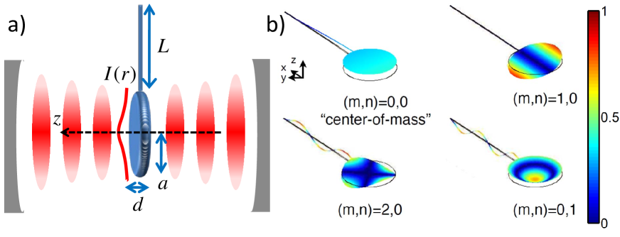
In this Letter, we propose a class of systems that should enable unprecedented -frequency products. The approach is based upon optically “trapping” a tethered membrane with low natural mechanical frequency in the anti-node of a strong optical standing wave (see Fig. 1a) Ashkin (2007). While there are many possible realizations, here we focus on a pendulum geometry, where a relatively large disk is supported by a single thin tether. The dielectric disk is attracted to the anti-node of the field, leading to an optical stiffening of its flexural modes. Under realistic conditions, the re-normalized mode frequencies can be significantly enhanced over the values expected under material stresses alone. Of particular interest is the “center-of-mass” (CM) mode, where the disk oscillates in the optical potential with negligible flexural motion. We show that this motion exhibits an extremely large ratio of potential energy stored in the optical field to strain energy, . This can yield a correspondingly large increase in the -frequency product over a conventional mechanical system due to the suppression of dissipation through internal friction.
Our approach to achieving long coherence times builds upon previous proposals, which suggested that the highly isolated CM mode of an optically levitated nanosphere Ashkin and Dziedzic (1976); Libbrecht and Black (2004) can enable quantum opto-mechanics in room-temperature environments Chang et al. (2010); Romero-Isart et al. (2010). Compared to the nanosphere, our approach has two significant advantages. First, the nanosphere scatters light omni-directionally, leading to motional heating via photon recoil. Suppression of recoil heating to reach the quantum regime requires spheres with sub-wavelength volumes, Chang et al. (2010). In contrast, the planar membrane primarily couples the counter-propagating components of the trapping beam, strongly reducing recoil heating even for large systems. Second, these membranes can be fabricated using well-established techniques that already yield excellent mechanical and optical properties in a number of experiments Wilson et al. (2009); Sankey et al. (2010). Our proposal thus shows how the ideas of optical levitation can be brought to bear upon “conventional” and practically deployable mechanical systems to yield remarkable coherence times.
We begin by considering the mechanical modes of a free, thin circular membrane with thickness and radius in the absence of any tethers. In equilibrium, the membrane is situated at , in the anti-node of an optical standing wave (see Fig. 1a). The optical field polarizes the dielectric disk, yielding a gradient force trap around . Absent any internal forces, the optical field traps a thin membrane () with a restoring frequency given by , where is the radial coordinate. Here is the beam intensity profile (assumed to be rotationally symmetric) in the direction transverse to , is the optical wavevector, is the mass density, and is the dielectric constant. Now including the internal stresses, the mechanical displacement field from equilibrium, , obeys
| (1) |
subject to free boundary conditions Landau and Lifshitz (1986) (also see Appendix). denote the Young’s modulus and Poisson’s ratio, respectively. Here and in the following, is understood to be the Laplacian in the transverse plane. Due to the rotational symmetry, we seek solutions of the form . The spatial modes are indexed by the number of nodal diameters and circles, (see Fig. 1b). For our numerical results we take material parameters GPa, , g/cm3, corresponding to stoichiometric silicon nitride Wilson et al. (2009), and an operating wavelength of m. For a free disk without optical forces, the fundamental flexural mode has natural frequency , or MHz for a disk of dimensions m, nm. There is also a trivial solution corresponding to the CM or mode with constant and zero frequency.
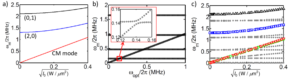
For a uniform intensity, , the natural radial functions remain eigenmodes of Eq. (7), but with re-normalized mechanical frequencies given by . Thus, the CM mode is now a non-trivial solution with frequency , but still retains a uniform spatial profile. The frequencies of all the flexural modes increase as well, with the CM mode remaining the lowest in frequency (see Fig. 2a).
The absence of energy stored in internal strains for the CM motion has the important implication of eliminating dissipation due to internal friction. Instead, the energy is stored in an optical potential that contributes no losses (but can contribute a recoil heating force, as described later). To quantify this, we consider the influence of thermoelastic damping on our system. We focus on thermoelastic damping because a) it can be analytically modelled Landau and Lifshitz (1986); Lifshitz and Roukes (2000), b) it is a fundamental limit even for “perfect” devices Lifshitz and Roukes (2000), and c) a number of micro-mechanical systems are approaching this limit Verbridge et al. (2006); Lee and Seshia (2009). We emphasize, however, that our conclusions are qualitatively correct for any internal dissipative process.
Thermoelastic damping arises because realistic materials have a non-zero coefficient of thermal expansion. The flexural motion creates local volume changes that then lead to temperature gradients and heat flow. Mechanical energy must be expended to drive this heat flow, leading to a finite . We make two simplifying assumptions to the general thermoelastic equations Landau and Lifshitz (1986); Lifshitz and Roukes (2000), which are well-justified in our system. First, we assume that the thermoelastic coupling is weak, so that the spatial modes determined by Eq. (7) are not altered to lowest order. Second, the strains vary most rapidly along the thin direction of the disk, and thus we ignore the relatively small transverse temperature gradients. The temperature field is given by , where satisfies the driven heat equation
| (2) |
with boundary conditions at . Here is the heat capacity per unit volume, is the thermal conductivity, and is the volumetric thermal expansion coefficient (we take J/cmK, W/mK, K-1 for SiN). The work done in driving the heat flow over one cycle is
| (3) |
and the thermoelastically limited quality factor is , where and are the energies stored in the optical field and strains, respectively. To good approximation, one finds that the thermoelastically limited -frequency product is given by (see Appendix). Thus the storage of energy in the optical field leads directly to an enhancement of the -frequency product. As a useful comparison, in the absence of optical trapping, an unstressed stoichiometric SiN film of thickness nm would have a -frequency product limited to Hz at room temperature, which only marginally exceeds the fundamental limit Hz needed for ground-state cooling. The -frequency product is also proportional to the number of coherent oscillations that the system can undergo before a single phonon is exchanged with the thermal bath, ( for the conventional membrane described above). A large value is critical to preparing and observing quantum superposition or entangled states Marshall et al. (2003); Genes et al. (2008).
We now examine thermoelastic damping of our free disk. Clearly, if is spatially uniform, the CM mode has no internal strains and experiences zero thermoelastic dissipation. A finite beam waist creates inhomogeneous optical forces that internal stresses must compensate for, which mixes CM and internal motion together (we still refer to this mixed mode as the “CM”). The mixing becomes significant when the variation in across the disk overtakes the natural rigidity of the system (as characterized by the natural fundamental frequency), and can be avoided by using sufficiently large beam waists or low intensities. In this regime, significant enhancements to the -frequency product should result.
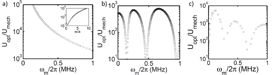
These effects are illustrated in Fig. 3a. For concreteness, we assume that the trapping beam has a Gaussian profile with waist , (for now, we ignore possible corrections due to distortion as the beam diffracts around the disk). In Fig. 3a, we plot the ratio for the CM mode as a function of its frequency, which is varied through the peak intensity . We use the same disk dimensions as before and a waist of m. The energy ratio monotonically decreases, reflecting the increased inhomogeneity in the optical potential. In the inset, a complementary process is illustrated, where the beam waist is varied, while the peak intensity is fixed such that MHz. The energy ratio increases indefinitely with and approaches infinity in the plane-wave limit.
We now consider the realistic pendulum geometry shown in Fig. 1a, where the tether provides an extremely weak restoring force for the “CM” motion of the disk. We first present a simplified analysis that isolates the role of the tether on the mode spectrum and -frequency product. Specifically, we treat the membrane as a perfectly rigid point particle of mass , which experiences an optical restoring force with frequency , while internal stresses alone act on the tether. Then, for a tether of length whose long axis is situated along , the displacement field (where ) satisfies the beam equation Landau and Lifshitz (1986),
| (4) |
Here denotes the width of the tether (assumed to be square in cross-section). The beam is clamped at , , while at the boundary conditions are given by and . The last equation describes the acceleration of the membrane due to optical restoring forces and the shear force imparted by the tether.
It is straightforward to solve for the system eigenmodes (see Appendix) and the results are summarized here. For large mass ratios between the membrane and tether, , the modes usually consist of a CM mode for the membrane with frequency and a set of discrete tether modes with frequencies , where . The CM mode spectrum is understood as a low-frequency “pendulum” mode (with natural frequency , where for our systems of interest) whose frequency can be strongly re-normalized by the optical force, while the tether mode spectrum results from the heavy membrane essentially acting as a second clamp. This description holds except near degeneracies , where coupling between the tether and membrane motions yields an avoided crossing whose width decreases with increasing mass ratio . This result is illustrated in Fig. 2b, for a mass ratio of (corresponding to the disk size considered earlier attached to a tether of length m and width nm). In Fig. 3b, we plot the energy ratios for the CM motion as a function of . Here, the strain energy is completely attributable to the tether, as we take the membrane to be a rigid object. The energy ratio is dramatically reduced near the avoided crossings, while away from these crossings, the energy ratio plateaus to a value near (see Appendix).
For a realistic tethered system (as in Fig. 1b) where the membrane is not perfectly rigid, mode mixing between the tether and membrane and mixing between the CM and internal membrane motion will occur simultaneously. We have numerically solved the full stress-strain equations for such a system using COMSOL, a commercial finite-element simulation package. A characteristic mode spectrum is plotted in Fig. 2c as a function of the peak trapping intensity , for parameters m, m, nm, and m. Away from avoided crossings, the modes can clearly be characterized as tether modes (gray points) or membrane modes (color). For our particular choice of beam waist size, the tethers themselves experience optical restoring forces, leading to a slight optical stiffening of tether modes that have displacements along the optical propagation axis. Comparing the membrane modes, the CM mode lies lower in frequency than the flexural modes, as in the case of a free disk. A nearly degenerate torsional mode also exists, which in principle should have no opto-mechanical coupling to the cavity field and can be ignored (see Appendix).
In Fig. 3c, we plot the energy ratio for the CM mode of our tethered structure as a function of its frequency. The features displayed here are clearly a combination of those appearing in the limiting cases of a free disk and a rigid disk attached to a tether. In particular, large plateaus in appear away from avoided crossings with tether modes. The plateau heights are higher than the limit predicted by the simple model, since the tether experiences an optical spring force as well. The decrease in the plateau heights with increasing CM frequency is associated with increased mixing between pure CM and internal membrane motion. For the realistic geometry considered here, an enhancement in the -frequency product on the order of compared to a conventional system can be realized at a frequency of MHz. For a thermoelastically limited system, this corresponds to a coherence time of .
Thus far, we have assumed that the trapping beam has a Gaussian profile. For cavity opto-mechanics Cleland (2009), it will be necessary to trap the membrane within a Fabry-Perot cavity, as illustrated in Fig. 1a. For example, here, a relatively strong beam could be used for trapping, while a second, weaker beam with a non-zero intensity gradient at the trap position would facilitate cooling of the CM motion or quantum state transfer processes Chang et al. (2010); Romero-Isart et al. (2010). The membrane scatters and diffracts the cavity light, which introduces two important effects. First, the mode will no longer be Gaussian, and the new optical mode accommodated by the cavity mirrors and the corresponding optical forces must be determined. Second, photon scattering out of the cavity reduces cavity finesse, and the associated random momentum kicks (“photon recoil”) imparted on the membrane lead to additional decoherence. We have performed detailed simulations of the modified cavity fields and coupled them to the equation of motion (7) for the membrane (see Appendix). We find that for realistic cavity geometries, a value of in a room-temperature environment can still be obtained, taking into account both thermoelastic processes and recoil heating. Remarkably, the coherence time of this system is comparable to that of a much smaller levitated nanosphere of radius nm Chang et al. (2010), or a conventional MHz oscillator with exceeding at a bath temperature of K.
We emphasize that our approach to reaching the quantum regime is fundamentally different than other “optical spring” proposals based upon optical backaction forces Braginsky and Vyatchanin (2002); Corbitt et al. (2007). In the latter case, the linear coupling of the mechanical displacement to the intra-cavity intensity can yield a dynamic optical spring effect. This effect, however, is accompanied by significant Raman scattering of the optical pump field, which causes phonons to be rapidly removed and added to the system. While this does not preclude ground state cooling Corbitt et al. (2007), a more detailed analysis (see Appendix) shows that it imposes severe limitations on the quantum coherence time and makes it difficult to prepare, e.g., quantum superposition states. In contrast, in our scheme, the phonons are truly long-lived excitations. Furthermore, regardless of the trapping scheme used, our analysis properly captures the role that strong, spatially non-uniform optical forces have in mixing internal motion, which is neglected in lowest-order opto-mechanical models but relevant to most flexural systems (see Appendix).
Although we have focused on thermoelastic losses in the above calculations, we expect similar improvements for any other internal damping mechanism. The key idea is that it is possible to circumvent natural material limits of damping by storing energy in a lossless optical field rather than the internal strain. By making the ratio of these energies large, , any internal losses can be suppressed by a corresponding degree. This fundamental observation allows one to design a novel class of mechanical systems that can be fabricated and deployed using conventional techniques, yet yield -frequency products that are several orders of magnitude higher than previous systems. We believe that this work will stimulate further investigation into the relationship between optical forces and material dissipation in a number of systems where the mechanical motion can be strongly renormalized by light Corbitt et al. (2007); Rosenberg et al. (2009). Furthermore, we anticipate that such studies will open up interesting possibilities for quantum manipulation of mechanical systems in room-temperature environments.
The authors thank Dal Wilson and Richard Norte for many helpful discussions. DEC acknowledges support from the NSF (Grant No. PHY-0803371) and the Gordon and Betty Moore Foundation through Caltech’s Center for the Physics of Information (CPI). KN acknowledges support from the CPI. HJK and OJP acknowledge support from the DARPA ORCHID program. HJK also acknowledges support from the NSF and DoD NSSEFF.
Appendix A Equation of motion for a free disk
Here we derive the equation of motion for a thin non-uniform disk of thickness , which has a reflection symmetry around (such that the surface of the plate is located at ). We are interested in the situation where the thickness is much less than the characteristic transverse size (e.g., the radius of a circular disk), such that its degree of freedom along the thin direction can be effectively eliminated and the flexural motion can be described by a two-dimensional displacement field . The equation of motion for can be obtained by a generalization of the derivation for a uniform disk given in Ref. Landau and Lifshitz (1986). Specifically, the energy associated with the displacement field is given by
| (5) |
Here are the Young’s modulus and Poisson’s ratio, respectively, while , etc. To derive the equilibrium field under some external normal pressure , we employ the variational principle to minimize the system energy. Under small variations , and following some algebra, the variation in can be written as the sum of an integral over the transverse area of the disk and two integrals over the circumference or edge of the disk,
| (6) |
Here are complicated expressions involving and whose forms are given below, while denotes the normal to the edge of the disk. The integral over the disk area yields the equilibrium equation of the disk, , or the dynamical equation can be obtained by replacing . Doing so, and including the effect of external optical forces, one finds
| (7) |
Here we have defined , and is understood to be the Laplacian in the transverse plane. As described in the main text, . For a disk with free boundary conditions at the edge, the quantities and are arbitrary on the boundary, so the coefficients should vanish, yielding the two boundary conditions. Defining and to be the normal and tangential directions to the edge of the disk, and as the local angle between and , these boundary conditions become
| (8) |
Appendix B Thermoelastic damping
We begin with Eqs. (2) and (3) in the main text that describe thermoelastic damping,
| (9) |
and
| (10) |
The first equation describes the driven heat equation along the thin direction of the membrane, with boundary conditions at . Here is the heat capacity per unit volume, is the thermal conductivity, and is the volumetric thermal expansion coefficient (we take J/cmK, W/mK, K-1 for SiN). The second equation describes the amount of work done in driving the heat flow over one cycle for a particular mechanical eigenmode. Solving Eq. (9) and substituting into Eq. (10), one finds
| (11) |
Let us now compare this quantity with the total strain energy given in Eq. (5). For simplicity, here we specialize to the case where the disk has a uniform thickness , such that
| (12) |
Note that and have similar forms, as both involve an integral over the membrane area of the quantity . The strain energy contains a second term, however, whose relative importance we characterize now. The second term can in fact be re-written as a line integral around the circumference of the membrane,
| (13) |
This boundary integral vanishes identically for certain types of shapes or boundary conditions, such as a clamped membrane. For our free disk, this boundary term does not identically vanish, but numerically we can confirm that the boundary contribution is small relative to the total strain energy. To good approximation then, we can write . This leads to the expression for the thermoelastically limited -frequency product given in the main text,
| (14) |
Appendix C Rigid membrane attached to tether
Here, we derive in detail the properties of a rigid membrane of mass attached to a single tether. As described in the main text, the tether has a length (oriented along the -axis) and a square cross-section of width . The displacement field (where ) satisfies the beam equation Landau and Lifshitz (1986),
| (15) |
The beam is clamped at , , while at the boundary conditions are given by and the force equation of the membrane attached there, . The last equation describes the acceleration of the membrane due to optical restoring forces and the shear force imparted by the tether.
The boundary conditions at require that the general solutions of Eq. (15) take the form
| (16) |
where the dispersion relation is given by and . The two boundary conditions at can be written in matrix form as , and the corresponding equation for the eigenfrequencies, , reads
| (17) |
where . With no optical forces () and large membrane to tether mass ratio , the solutions to the above mode equation consist of a low-frequency “pendulum mode” with frequency and a set of discrete tether oscillation modes with frequencies , which approximately satisfy the relation . For sufficiently large (i.e., large enough ), the natural tether frequencies asymptotically approach . With optical forces, a power series expansion of Eq. (17) reveals that the pendulum mode frequency becomes re-normalized to the value , which can be associated with the CM mode.
Generically, for sufficiently large optical forces , a large membrane mass means that the eigenvalue condition of Eq. (17) is approximately satisfied when , which means that the solutions typically consist of a single CM mode with frequency or tether modes satisfying . When both conditions are satisfied simultaneously (e.g., near a degeneracy point), the second term of Eq. (17) must be taken into account, which yields avoided crossings that mix the tether and CM modes together.
We now consider the ratio of energy stored in the optical field to the strain energy, , for the CM motion away from an avoided crossing. The energy stored in the optical field for this system is simply given by , while the strain energy in the beam is given by Landau and Lifshitz (1986)
| (18) |
It can readily be shown that for frequencies where , the spatial modes are given to good approximation by
| (19) |
Then, when the CM mode is positioned halfway in between two tether modes (say at a frequency ), evaluation of the stored energies yields .
Appendix D Dynamic optical spring
An increase in the frequency of a mechanical mode can also be achieved through a dynamic backaction effect in an opto-mechanical system Braginsky and Vyatchanin (2002); Corbitt et al. (2007), as opposed to the “static” optical potential considered in our work. We briefly describe the dynamic effect and compare the two mechanisms here. Specifically, we consider a mechanical degree of freedom whose displacement is linearly coupled to the optical cavity frequency. The corresponding Hamiltonian for such a system in a rotating frame is Marquardt et al. (2007); Wilson-Rae et al. (2007)
| (20) |
Here is the annihilation operator for the optical mode, are the position and momentum operators corresponding to the mechanical resonator, is the natural mechanical frequency, is the frequency detuning between an external pump field driving the optical cavity and the optical resonance frequency (when the mechanical resonator is in equilibrium), is the driving amplitude, and is the optical cavity frequency shift per unit mechanical displacement. In addition to the Hamiltonian terms, the optical cavity is assumed to have losses characterized by a linewidth .
For weak opto-mechanical coupling, it is customary to linearize the optical cavity dynamics around the classical steady-state value (here we have incorporated a steady-state shift of the optical resonance frequency into our definition of the detuning ), and eliminate the cavity to yield an effective susceptibility of the mechanical displacement in response to an external force Marquardt et al. (2007). Specifically, one finds
| (21) |
Here we have defined an effective opto-mechanical driving amplitude , and is the optical cavity frequency shift per unit mechanical zero-point uncertainty. In the perturbative limit, this expression can be written in terms of the susceptibility of a simple oscillator with an effective linewidth and frequency that is modified due to opto-mechanical interactions, . The effective linewidth and mechanical frequency shift can be interpreted as resulting from optically-induced cooling (or heating) and a dynamic optical spring constant, respectively. In the relevant regime of large detuning , and when the optical spring is dominant compared to the natural mechanical frequency, the effective mechanical frequency is given by
| (22) |
The damping rate is given by
| (23) |
which is interpreted as the difference between anti-Stokes and Stokes scattering rates. Note that for positive detuning , the opto-mechanical interaction yields an increase in the mechanical frequency but an anti-damping force (). One can achieve simultaneous stiffening and cooling by employing multiple beams with different amplitudes and detunings Corbitt et al. (2007), but for our purposes it is sufficient to consider only the beam that leads to stiffening.
We wish to consider the ratio of the effective mechanical frequency to the rate of decoherence induced by optical Raman scattering, which is given by the sum of the anti-Stokes and Stokes scattering rates. In the relevant limit of large detuning and dominant optical spring effect, one finds
| (24) |
This result states that the cavity must be driven very far off resonance in order to yield a frequency shift that is much larger than the decoherence rate. Operating at large detuning in turn requires extremely large cavity input powers to get an appreciable optical spring effect. As an example, we consider the dynamic spring constant for a realistic geometry, such as a Fabry-Perot cavity of length cm and cavity finesse (with the cavity linewidth given by kHz for our specific parameters). The optical driving amplitude is related to the input power through for perfect in-coupling efficiency, while the opto-mechanical interaction strength is of order . The operating wavelength is taken to be m. We also assume that the SiN membrane has a radius of radius m and that it undergoes pure CM motion (such that its effective motional mass is the same as the physical mass). Then, an input power of kW is required if one wants to achieve a number of coherent oscillations and an effective mechanical frequency of 1 MHz. This corresponds to an input intensity of W/m2 for a beam focused to a size comparable to the membrane radius.
In contrast, in our static trapping scheme, a comparable mechanical frequency and coherence time can be achieved for an intra-cavity intensity of W/m2, and the cavity can be driven resonantly to facilitate the intra-cavity field buildup. Because the static trap results in the membrane being trapped at an anti-node, there is no linear opto-mechanical coupling for the trapping field and the lowest-order opto-mechanical coupling is quadratic in nature. The decoherence rates caused by anti-Stokes and Stokes scattering in this case (at frequencies ) have been calculated in Ref. Nunnenkamp et al. (2010) and are extremely rare for our realistic systems (occurring at a sub-Hz level). In fact, the dominant decoherence mechanism arising from the trapping beam is due to scattering out of the cavity and the photon recoil heating imparted on the membrane, as described later.
Appendix E Modification of opto-mechanical coupling strengths
Our theory of optical trapping of membranes predicts dramatic corrections to the simple model of opto-mechanical interactions given by Eq. (20), when the optical restoring forces (either static or dynamic) become large compared to the natural ridigity of the membrane. In this scenario of strong optical forces, the mechanical mode shape and thus the opto-mechanical coupling strength become functions of intensity as well, with generally decreasing with larger intensity. The origin of this effect is intuitively seen by considering a membrane that interacts with a Gaussian cavity mode whose beam waist is smaller than the membrane radius . Then, if the optical restoring forces are large compared to the membrane stiffness, the optical beam in fact resembles a new boundary condition that “pins” the region of the membrane into place. This reduces the overlap between the mechanical displacement field and the optical beam, and thus .
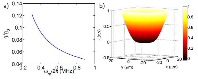
This effect is illustrated in Fig. 4 for a free SiN membrane of thickness nm and m, interacting with a beam of waist m. In this calculation the membrane is statically trapped, although a similar effect would occur for sufficiently large dynamical backaction forces as well. In Fig. 4a, we calculate the opto-mechanical coupling strength (to another cavity mode with the same beam waist but which exhibits an intensity gradient at the membrane position) as a function of the CM frequency, which is varied through the intensity of the trapping beam. The value of is calculated using the expression Wilson et al. (2009)
| (25) |
In Fig. 4a, we have normalized the obtained value of with the value if the motion were purely CM, where the displacement field is constant. At larger frequencies, dramatically decreases, reflecting the “pinning” effect that the optical force has on the center of the membrane. This is also directly seen in Fig. 4b, where we plot the displacement field for a CM frequency kHz. Incidentally, Eq. (25) also makes it apparent that the torsional membrane mode described in the main text has zero opto-mechanical coupling, due to the odd versus even reflection symmetries of the torsional mode and cavity mode, respectively.
Appendix F Tethered membrane inside a Fabry-Perot cavity
The membrane should be trapped within a Fabry-Perot cavity in order to enable optical cooling and reach the quantum regime Wilson-Rae et al. (2007); Marquardt et al. (2007). The membrane diffracts and scatters the cavity light, which introduces two important effects. First, the optical mode will no longer be Gaussian, and the new optical mode accommodated by the mirrors and the corresponding optical forces must be determined. Second, scattering out of the cavity reduces the cavity finesse, and the associated photon recoil acts as a stochastic force that heats the membrane motion. To calculate the cavity modes in the presence of the membrane, we use a modified Fox-Li propagation technique Fox and Li (1968), as briefly described below.
Specifically, the electric field is treated within the scalar paraxial approximation, and thus it is completely described by its transverse profile . This approximation is justified by noting that the disk should primarily diffract light at small angles around the -axis, where is the optical wavevector. Within this approximation, free propagation over a distance is accounted for by a phase shift in the Fourier transform of the field profile, . In our case, we are interested in systems with rotational symmetry, and thus the transforms are implemented through the quasi-discrete Hankel transform described in Ref. Yu et al. (1998). Reflection off of a circular mirror with radius of curvature and reflectance is characterized by the real-space transformation . Similarly, at the membrane location, the wave front experiences reflection and transmission amplitudes , , respectively, which multiply the incident real-space wave front there. For the case of a non-uniform disk, we approximate with the formulas for an infinite thin dielectric sheet of uniform thickness, replacing the uniform thickness with the local thickness. Note that an initial wave front incident on the membrane thus splits into two wave fronts (a reflected and transmitted field), and we keep track of the multiple scattered fields to all orders in order to calculate the field buildup or cavity eigenmodes. In contrast, the original technique of Ref. Fox and Li (1968) only accounts for transmission. Thus, our approach properly captures the effects of the reflected amplitude and back-scattered angle. Furthermore, our modified technique reveals specifically at what frequencies resonances should occur.
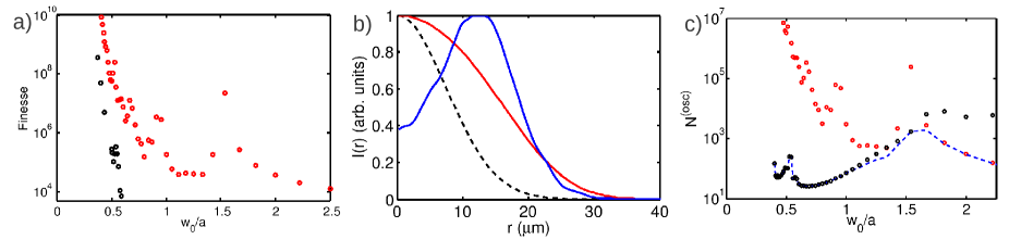
We now discuss the effect of the membrane on the cavity finesse. As realistic parameters, we consider a membrane placed symmetrically in the center of an optical cavity of length cm with spherical mirrors having radii of curvature cm and perfect reflectivity (such that the entire cavity linewidth is attributable to scattering from the membrane). The transverse extent of the spherical mirror surfaces is mm, i.e., all portions of the beam front with are scattered out and set to zero upon reflection at the mirror. An empty cavity in this configuration yields a Gaussian mode of waist m in the center. In Fig. 5a, we plot the membrane-limited cavity finesse for a membrane of uniform thickness nm and varying radius (black circles). Clearly, cavity losses are negligible when the nominal waist is small compared to the disk radius, . In the regime , however, the finesse rapidly drops, which is attributable to scattering by the hard edges of the disk. This effect is strongly reduced by “softening” or apodizing the disk edge Born et al. (2000). In Fig. 5a (red circles), we also plot the finesse for a membrane whose thickness tapers down to zero at the edge, where nm is the maximum thickness. Remarkably, the apodization can improve the cavity finesse by several orders of magnitude. The modification of the cavity modes by the membrane is illustrated in Fig. 5b, where we plot the transverse profile at the membrane position for some representative apodized disk sizes.
We find the CM eigenmodes of the apodized disk by using Eq. (7), where the optical potential is now evaluated using the modified cavity mode profiles. The thermoelastic limit is subsequently calculated using Eqs. (2) and (3) in the main text. In Fig. 5c, the number of oscillations due to thermoelastic damping is plotted (in black). Here the circulating intra-cavity power is chosen such that the CM frequency is fixed at MHz. We next consider the effect of photon recoil heating. We assume that each scattered photon contributes the maximum possible momentum kick of along the -axis, giving rise to a momentum diffusion process Chang et al. (2010), where is the photon scattering rate. Converting this expression into a jump rate, it can be shown that the number of coherent oscillations before a jump in the phonon number can be written as
| (26) |
Here is the maximum cavity intensity (which in general does not need to be at the center of the membrane due to mode distortion), , is the volume of the disk, and is the cavity mode volume. Assuming that the cavity mode is not significantly distorted and that the beam waist such that the entire membrane experiences the optical force, one can approximate and . In this case the number of coherent oscillations scales roughly as . Note that this result is purely geometric in nature and also scales directly with the cavity finesse (which itself depends on ). In Fig. 5c, we plot for the apodized disk (in red). Combining the effects of thermoelastic damping and recoil heating, the total number of coherent oscillations is given by (blue curve). It can be seen that an apodized disk of radius m can support a coherence time of in a room temperature environment.
References
- Cleland (2009) A. Cleland, Nature Phys. 5, 458 (2009).
- Wilson et al. (2009) D. J. Wilson, C. A. Regal, S. B. Papp, and H. J. Kimble, Phys. Rev. Lett. 103, 207204 (pages 4) (2009).
- Marshall et al. (2003) W. Marshall, C. Simon, R. Penrose, and D. Bouwmeester, Phys. Rev. Lett. 91, 130401 (2003).
- Genes et al. (2008) C. Genes, A. Mari, P. Tombesi, and D. Vitali, Phys. Rev. A 78, 032316 (2008).
- Geraci et al. (2010) A. A. Geraci, S. B. Papp, and J. Kitching, Phys. Rev. Lett. 105, 101101 (2010).
- Li et al. (2010) T. Li, S. Kheifets, D. Medellin, and M. G. Raizen, Science 328, 1673 (2010).
- Ashkin (2007) A. Ashkin, Optical Trapping and Manipulation of Neutral Particles Using Lasers: a Reprint Volume with Commentaires (World Scientific, 2007).
- Ashkin and Dziedzic (1976) A. Ashkin and J. M. Dziedzic, Appl. Phys. Lett. 28, 333 (1976).
- Libbrecht and Black (2004) K. G. Libbrecht and E. D. Black, Phys. Lett. A 321, 99 (2004).
- Chang et al. (2010) D. E. Chang, C. A. Regal, S. B. Papp, D. J. Wilson, J. Ye, O. Painter, H. J. Kimble, and P. Zoller, Proc. Natl. Acad. Sci. USA 107, 1005 (2010).
- Romero-Isart et al. (2010) O. Romero-Isart, M. L. Juan, R. Quidant, and J. I. Cirac, New J. Phys. 12, 033015 (2010).
- Sankey et al. (2010) J. C. Sankey, C. Yang, B. M. Zwickl, A. M. Jayich, and J. G. E. Harris, Nature Phys. 6, 707 (2010).
- Landau and Lifshitz (1986) L. D. Landau and E. M. Lifshitz, Theory of elasticity, 3rd ed. (Butterworth-Heinemann, Boston, 1986).
- Lifshitz and Roukes (2000) R. Lifshitz and M. L. Roukes, Phys. Rev. B 61, 5600 (2000).
- Verbridge et al. (2006) S. S. Verbridge, J. M. Parpia, R. B. Reichenbach, L. M. Bellan, and H. G. Craighead, J. Appl. Phys. 99, 124304 (pages 8) (2006).
- Lee and Seshia (2009) J. E.-Y. Lee and A. A. Seshia, Sens. Actuators A 156, 28 (2009).
- Braginsky and Vyatchanin (2002) V. B. Braginsky and S. P. Vyatchanin, Phys. Lett. A 293, 228 (2002).
- Corbitt et al. (2007) T. Corbitt, Y. Chen, E. Innerhofer, H. Müller-Ebhardt, D. Ottaway, H. Rehbein, D. Sigg, S. Whitcomb, C. Wipf, and N. Mavalvala, Phys. Rev. Lett. 98, 150802 (2007).
- Rosenberg et al. (2009) J. Rosenberg, Q. Lin, and O. Painter, Nat. Photonics 3, 478 (2009).
- Marquardt et al. (2007) F. Marquardt, J. P. Chen, A. A. Clerk, and S. M. Girvin, Phys. Rev. Lett. 99, 093902 (pages 4) (2007).
- Wilson-Rae et al. (2007) I. Wilson-Rae, N. Nooshi, W. Zwerger, and T. J. Kippenberg, Phys. Rev. Lett. 99, 093901 (pages 4) (2007).
- Nunnenkamp et al. (2010) A. Nunnenkamp, K. Børkje, J. G. E. Harris, and S. M. Girvin, Phys. Rev. A 82, 021806 (2010).
- Fox and Li (1968) A. G. Fox and T. Li, IEEE J. Quantum Electron. 4, 460 (1968).
- Yu et al. (1998) L. Yu, M. Huang, M. Chen, W. Chen, W. Huang, and Z. Zhu, Opt. Lett. 23, 409 (1998).
- Born et al. (2000) M. Born, E. Wolf, and A. B. Bhatia, Principles of optics: electromagnetic theory of propagation, interference and diffraction of light (Cambridge University Press, 2000).