Role of incoherent substrate reflections in photonic crystal spectroscopy
Abstract
A method is presented for modelling the optical properties of a
photonic crystal structure mounted on a substrate which is thick
enough that the light reflected from the back is incoherent with
reflections from the front. Transmission and reflection spectra are
presented for the cases where the structure is a multilayer planar
microcavity and an opal photonic crystal. The contributions from the
incoherent reflections can be very large, and in the photonic crystal
case, change the positions of the spectral peaks.
There are many situations where a photonic crystal structure which is studied experimentally is mounted on a thick substrate. In modelling the optical properties of the actual structure, we need to consider the effects of interference between light reflected off different interfaces. However, if we also allow interference between waves reflected from the structure and off back of the substrate, the spectra which are obtained are very unrealistic, being dominated by closely spaced Fabry-Perot fringes. This problem is typically avoided in calculations by treating the substrate as semi-infinite, eliminating any reflections. In reality, the interference effects are not seen because inhomogeneities in the substrate, such as thickness variations, mean that any waves which has passed through the substrate is effectively incoherent with the front reflections. In this letter, we present a simple but much more realistic theoretical treatment which incorporates multiple reflections in the substrate as incoherent waves. Our results show that these reflections can make very significant contributions to the spectra, so the semi-infinite substrate approach is not appropriate for accurate comparisons with experimental data.
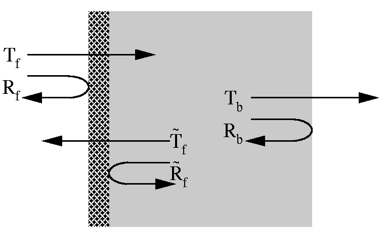
The method we describe is very adaptable, and can be applied to any structure for which the intensity transmittance and reflectance on a semi-infinite substrate can be calculated, either analytically or numerically. As indicated in Fig.(1), we call these quantities and for light passing from air into the substrate, and for the reverse direction. We also require the the transmittance and reflectance of the back of the substrate, and , which come from the standard Fresnel expressions.

The total transmittance, , is obtained by summing over an infinite number of incoherent reflections from the surfaces of the substrate. If the absorption coefficient of the substrate, , is non-zero there is an attenuation on every pass. The result is
| (1) |
Similarly the total reflectance, , is
| (2) |
Since there is no interference, these results are independent of the thickness of the substrate, , except for the attenuation due to absorption.
For a transparent substrate, with no structure on the surface, the reflectances are all the same, , and also . Eqs.(1) and (2) then reproduce the well known results for incoherent reflections,
| (3) |
A further check is the case of a thin film on the surface of the substrate. The transmittance of such a film with incoherent substrate reflections is given by Swanepoel[1]. It is straight forward to obtain expressions for and for a simple film, and Eq.(1) then correctly reproduces this result[2].

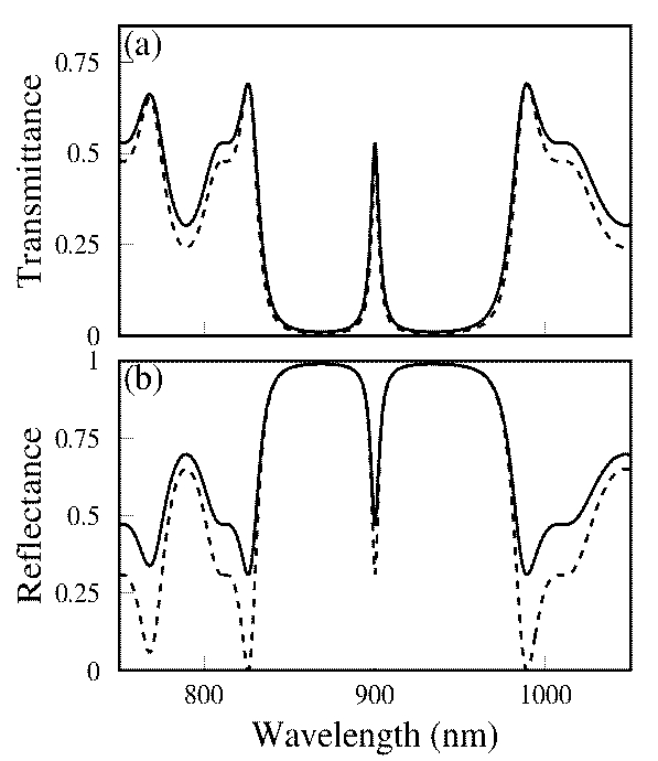
Turning to the case of a one-dimensional photonic crystal, we next calculate the properties of a planar microcavity on a thick substrate. The parameters used are typical for a GaAs/AlGaAs structure, with a design wavelength of nm. The cavity is a thickness[3] layer of refractive index 3.5. with the mirrors on either side comprising 10 bilayer Bragg stacks with layer thicknesses and high and low indicies of 3.5 and 3. The substrate index is 3.5 and its absorption coefficient .
In this case, it is easiest to obtain the front coefficients, , , and from a transfer matrix calculation[4]. We have done this numerically, and the transmission and reflection spectra calculated using Eqs.(1) and (2) are shown in Fig.(2). The dashed lines on the figure show the results obtained when multiple reflections in the substrate are ignored, by putting ; for the reflectance, this is simply , the structure reflectance, while for the transmittance it is . The incoherent reflections always add to and , and their contribution is significant, except where the reflectance of the structure is high, and no light passes through the microcavity into the substrate. Where the structure reflectance is zero or very small, all the light passes through in both directions, and we just see the reflectance and transmittance of the back of the substrate, which are and 0.69 respectively.

The situation becomes more complicated when we consider a two or three dimensional photonic crystal fabricated on a substrate, so the structure has an in-plane periodicity. The effect of this periodicity is to give rise to diffraction, so for some wavelengths a single incident wave will produce multiple diffracted waves in the substrate, or in both substrate and air. Despite this, Eqs.(1) and (2) still apply, though the symbols needs to be reinterpreted as matrices.
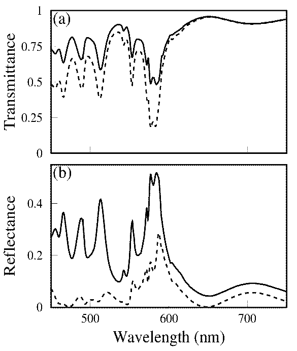
Consider a wavelength at which there are waves in air, and waves in the substrate, including both straight through and diffracted directions. In general, photonic crystals cause mixing of polarisations, so both TE and TM waves need to be included and the values will be twice the number of directions. We can then describe the front reflection and transmission processes by matrices; for example, becomes a matrix, whose element gives the intensity generated in substrate wave for illumination in exterior wave . We assume again that there is some method available to obtain these matrices; in the example presented in Fig.(3), they are calculated using the scattering matrix method of Ref.[5]. The back coefficients and become diagonal matrices, with elements given by the standard Fresnel expressions for finite angle transmittance and reflectance. Knowing these matrix elements, we can add up intensities, as in the derivation of Eqs.(1) and (2), with the complication that we now need to sum over every possible path, comprising the combinations of the different directions and polarisations that can occur on each pass through the substrate. This summation is obtained by replacing expressions such as by the equivalent matrix products, since the sum over the internal index in the product replicates the sum over paths. Eqs.(1) and (2) then give the total transmittance and reflectance and , now as matrices.
In Fig.(3), we show the results of this procedure for an opal structure on a glass substrate. The opal consists of three hcp-ordered layers of 500nm spheres, with refractive index 1.5; the substrate also has index 1.5 and absorption . For wavelengths longer than 649.5nm, there is no diffraction, and the physics is similar to the planar microcavity, though we have matrices because of the polarisation mixing induced by the photonic crystal. The structure reflectance is very low, so the substrate contributes just one back reflection, which adds a constant to the reflectance but does not affect the transmittance.
At shorter wavelengths, there are six diffracted directions in the substrate, but, in the range of the figure, none in air, so and . Again, the structure reflectance is quite low, but the diffracted waves, unable to propagate in air, experience total internal reflection at the back of the substrate. They then interact with the opal again and are partially re-diffracted back into the normal direction, to provide strong contributions to both the reflectance and the transmittance. It is notable in the reflectance that these contributions not only are much larger than those from the front reflection, but they are also different spectrally, with peaks appearing at different wavelengths. It is clear from this that it may be very misleading to neglect the substrate reflections, though we believe that this has been done in all previous published calculations.
In conclusion we have shown that, if transmission and reflection spectra can be calculated for an optical structure, there is a very simple formulism by which to add the contributions due to multiple incoherent reflections occuring when the structure is mounted on a finite substrate. We have used this method to calculate the optical properties of a planar microcavity structure and an opal photonic crystal, and shown that the substrate reflections can modify very significantly the spectra which are obtained.
References
- [1] R. Swanepoel, “Determination of the thickness and optical constants of amorphous silicon”, J. Phys. E 16, 1214 (1983).
- [2] Details of the derivation are given in the accompanying supplementary information.
- [3] The thicknesses are all given in terms of the wavelength in the medium, that is .
- [4] See, for example, E. Hecht, “Optics”, 2nd ed. (Addison Wesley, Reading, MA, 1987), pp. 373- 375.
- [5] D. M. Whittaker and I. S. Culshaw, “Scattering matrix treatment of patterned multilayer photonic structures”, Phys. Rev. B 60, 2610 (1999).
Supplementary Information: Derivation of transmission of thin film on a substrate
In this section, we calculate the total transmission of a thin film of thickness and refractive index on a transparent substrate with index . We show that our result agrees with the expression given in Eq.(4) of Ref.[1]. The derivation is for the case where the film is weakly absorbing, so there is attenuation of light passing through the film (given by the attenuation factor, ), but the imaginary part of the refractive index, , is neglected in the expressions for the reflection and transmission coefficients at the interfaces.

We first evaluate and for the thin film. They are obtained, in the usual way, using a similar approach to our derivation of Eqs.(1) and (2), except adding amplitudes because the reflections are coherent. On each double pass through the film, there is a phase change and an amplitude reduction, , which are given by
| (S1) |
The transmittance of the film is then
| (S2) |
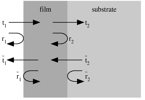
where the amplitude reflection and transmission coefficients at the interfaces, , , , , , , and , are defined in Fig.(S1). Using the the Fresnel formulae, they are
| (S3) |
Substituting these expressions into Eq.(S2), we obtain
| (S4) |
where the denominator is
| (S5) |
The reflectance of the film from the substrate side is
| (S6) |
where we have used the identity
| (S7) |
Substituting from Eq.(S3), we get
| (S8) |
where is again given by Eq.(S5) and
| (S9) |
The back transmittance and reflectance are obtained from the Fresnel formulae for the substrate-air interface:
| (S10) |
We are now in position to evaluate total transmittance using Eq.(1), with . We have
| (S11) |
Substituting and , the denominator of this expression becomes
| (S12) |
We evaluate the powers of separately. First, for :
| (S13) |
for :
| (S14) |
and for :
| (S15) |
where the coefficients , and are the same as in Ref.[1]. Putting these parts back together, and defining , Eq.(S11) becomes
| (S16) |
which is Eq.(4) of Ref.[1].