Emulation of floating memcapacitors and meminductors using current conveyors
Abstract
We suggest circuit realizations of emulators transforming memristive devices into effective floating memcapacitive and meminductive systems. The emulator’s circuits are based on second generation current conveyors and involve either four single-output or two dual-output current conveyors. The equations governing the resulting memcapactive and meminductive systems are presented.
Index Terms:
Memory, Analog circuits, Analog memories.The class of memory circuit elements [1] involves memristors [2, 3], memcapacitors [1] and meminductors [1], namely resistors, capacitors and inductors, respectively, which retain memory of the past dynamics. While there are many discovered experimental realizations of memristive systems, the number of systems showing memcapacitive and meminductive behavior is still very limited [1]. Therefore, electronic circuits that emulate the behavior of memcapacitive and meminductive elements are of significant interest. One way to obtain memcapacitive or meminductive response is to use mutators [4, 5]. However, recently suggested mutators have some limitations [4, 5]. For instance, the mutators discussed in reference [4] realize grounded memcapacitive and meminductive systems connected in series with a resistor. The mutator from reference [5] simulates a grounded memcapacitive system. For applications in electronics, however, it is desirable to have emulators of memcapacitive and meminductive systems that can be connected between any two voltages, and that do not involve any additional resistances. Such circuits are proposed in this work.
The suggested circuits transform a time-dependent response of a memristive system into effective floating memcapacitive and meminductive responses. The memristive system is defined by the following equations:
| (1) | |||||
| (2) |
where and are the current through and the voltage across the memristive system, respectively [3], is the memristance (time-dependent resistance), is a vector of the internal state variables and is a device-specific function. The memristive system could be realized by a physical material/system [1] (with given, e.g., by the equations in Ref. [6]) or it could be emulated as suggested by the present authors in Refs. [4, 7, 8].
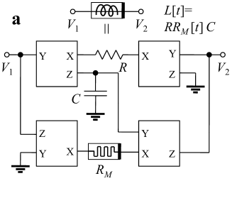
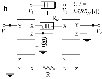
Figure 1 shows circuits of mutators employing four single-output second generation current conveyors (CCII+) [9, 10]. The main circuit’s topology is based on the floating inductance simulation circuit [11]. In addition to four active elements, each circuit uses three passive elements such as the memristive system described by Eqs. (1-2), and standard linear , and . The operation of a current conveyor can be characterized by the following relations: , , . By straightforward analysis of the circuit shown in Fig. 1(a) we find that the circuit’s response between terminals 1 and 2 is described by
| (3) | |||||
| (4) |
where the flux is given by . The analysis of the circuit presented in Fig. 1(b) results in the following system’s equations:
| (5) | |||||
| (6) |
It is readily seen that Eqs. (3-4) and (5-6) describe floating flux-controlled meminductive systems [1] and voltage-controlled memcapacitive systems [1], respectively. If we consider equation (3) and algebraically solve it with respect to the flux (assuming a unique solution at any given time), we can then substitute the result into (4) and obtain equations of a current-controlled meminductive system. The same can be done for Eqs. (5) and (6) thus transforming a voltage-controlled memcapacitive system into a charge-controlled one, provided a unique solution of Eq. (5) exists at any given time.
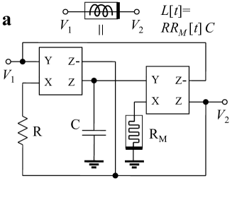
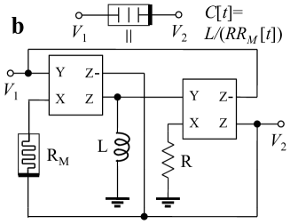
It was previously demonstrated that dual-output current conveyors can be used to reduce the number of active components in different circuits [12, 13, 14]. Fig. 2 represents emulators of meminductive and memcapacitive systems based on a floating-inductor simulation circuit [12]. Each of the circuits in fig. 2 employs one memory element (memristor), two other passive and two active elements. The equations governing the effective meminductive and memcapacitive behaviors are the same as Eqs. (3-4) and Eqs. (5-6), respectively.
In conclusion, we have presented emulators of floating memcapacitive and meminductive systems using second generation current conveyors involving either four single-output or two dual-output current conveyors. The resulting circuits mutate memristive system’s dynamics into an effective memcapacitive and meminductive response. Since memristor emulators can be easily made from off-the-shelf components [7, 8, 4], we expect these mutators to find widespread use in electronic applications with memdevices.
References
- [1] M. Di Ventra, Y. V. Pershin, and L. O. Chua, “Circuit elements with memory: Memristors, memcapacitors, and meminductors,” Proc. IEEE, vol. 97, no. 10, pp. 1717–1724, 2009.
- [2] L. O. Chua, “Memristor - the missing circuit element,” IEEE Trans. Circuit Theory, vol. 18, pp. 507–519, 1971.
- [3] L. O. Chua and S. M. Kang, “Memristive devices and systems,” Proc. IEEE, vol. 64, pp. 209–223, 1976.
- [4] Y. V. Pershin and M. Di Ventra, “Memristive circuits simulate memcapacitors and meminductors,” Electronics Letters, vol. 46, pp. 517–518, 2010.
- [5] D. Biolek and V. Biolkova, “Mutator for transforming memristor into memcapacitor,” El. Lett., vol. 46, p. 1428, 2010.
- [6] Y. V. Pershin, S. La Fontaine, and M. Di Ventra, “Memristive model of amoeba learning,” Phys. Rev. E, vol. 80, p. 021926, 2009.
- [7] Y. V. Pershin and M. Di Ventra, “Practical approach to programmable analog circuits with memristors,” IEEE Trans. Circ. Syst. I, vol. 57, p. 1857, 2010.
- [8] ——, “Experimental demonstration of associative memory with memristive neural networks,” Neural Networks, vol. 23, p. 881, 2010.
- [9] A. Sedra and K. Smith, “A second-generation current conveyor and its applications,” IEEE Trans. Circ. Th., vol. CT17, p. 132, 1970.
- [10] B. Wilson, “Recent developments in current conveyors and current-mode circuits,” IEE Proc. G, vol. 137, pp. 63–77, 1990.
- [11] W. Kiranon and P. Pawarangkoon, “Floating inductance simulation based on current conveyors,” Electronics Letters, vol. 33, pp. 1748–1749, 1997.
- [12] K. Pal, “Modified current conveyors and their applications,” Microelectronics Journal, vol. 20, p. 37, 1989.
- [13] A. M. Soliman, “Current conveyor filters: Classification and review,” Microelectronics Journal, vol. 29, pp. 133–149, 1998.
- [14] W. Tangsrirat and W. Surakampontorn, “High output impedance current-mode universal filter employing dual-output current-controlled conveyors and grounded capacitors,” AEU - International Journal of Electronics and Communications, vol. 61, pp. 127–131, 2007.