Author(s) in page-headRunning Head
gamma rays: bursts — gamma rays: polarization — gamma rays: observation
Gamma-Ray Burst Polarimeter – GAP – aboard the Small Solar Power Sail Demonstrator IKAROS
Abstract
The small solar power sail demonstrator “IKAROS” is a Japanese engineering verification spacecraft launched by H-IIA rocket on May 21, 2010 at JAXA Tanegashima Space Center. IKAROS has a huge sail with 20 m in diameter which is made of thin polyimide membrane. This sail converts the solar radiation-pressure into the propulsion force of IKAROS and accelerates the spacecraft. The Gamma-Ray Burst Polarimeter (GAP) aboard IKAROS is the first polarimeter to observe the gamma-ray polarization of Gamma-Ray Bursts (GRBs) during the IKAROS cruising phase. GAP is a tinny detector of 3.8 kg in weight and 17 cm in size with an energy range between 50–300 keV. The GAP detector also plays a role of the interplanetary network (IPN) to determine the GRB direction. The detection principle of gamma-ray polarization is the anisotropy of the Compton scattering. GAP works as the GRB polarimeter with the full coincidence mode between the central plastic and the surrounding CsI detectors. GAP is the first instrument, devoted for the observation of gamma-ray polarization in the astronomical history. In this paper, we present the GAP detector and its ground and onboard calibrations.
1 Introduction
Gamma-Ray Bursts (GRBs) are the most energetic explosion in the universe and most of all occur at the cosmological distance beyond the redshift of . The current record for the highest redshift is GRB 090423 at (e.g. [Tanvir et al. (2009), Salvaterra et al. (2009)]). At the brightest case, the isotropic luminosity reaches . Although many physical property about GRBs are revealed after the discovery of afterglows (Costa et al., 1997), we have little knowledge about their emission mechanism to produce gamma-rays. Theoretically, the prompt emissions and the following afterglows are thought to be generated by the synchrotron radiation in the relativistic jet. The electrons are accelerated to almost light speed by the relativistic shocks, and the strong magnetic field above is generated within the jet in a short time interval of prompt phase (e.g. Rees & Meszaros (1992); Piran (1999)). In this case, the polarization degree of emitted photons is expected to be very high. Therefore, the direct measurement of the polarization degree of the prompt emission is a key to probe their emission mechanism and the site.
There are several empirical correlations between the rest-frame physical quantities of GRBs and their luminosity (or isotropic energy ). The variability–luminosity correlation indicates that more variable events are more luminous (Fenimore & Ramirez-Ruiz, 2000). The lag–luminosity correlation is reported by Norris et al. (2000) and Schaefer et al. (2001). Each pulse in the prompt emission has a time delay of the soft-band emission compared with the hard-band one. This correlation shows that the events with large spectral time lag are dimmer than ones with short lag. These two correlations are based on the temporal behaviors of prompt emission. Several correlations concerning the spectral property have also been suggested. Amati et al. (2002) found a very tight correlation between the spectral peak energy () and the isotropic energy () (see also Amati et al. (2006)). This – correlation was confirmed and extended toward X-ray flashes by Sakamoto et al. (2004) and Lamb et al. (2004). Independently, Yonetoku et al. (2004) reported similar but tighter correlation between and the 1-second peak luminosity () called the – correlation. Moreover, using the jet opening half-angle, Ghirlanda et al. (2004) found that strongly correlates with the collimation-corrected gamma-ray energy (). However the physical reasons for these correlations are not established yet. These empirical properties may indicate that there are well-ordered physics in the complex behaviour of prompt GRBs. Then the emission mechanism may play an important role in these correlations, and the observation of gamma-ray polarization is a key to reveal the emission mechanism.
The first X-ray polarimeter is a Bragg reflection type aboard the OSO-8 satellite in 1970s (Kestenbaum et al., 1976). This polarimeter works for monochromatic X-rays of 2.6 keV and 5.2 keV. The first detection of X-ray polarization has been done for Crab nebula (Weisskopf et al., 1976) with % at 2.6 keV and % at 5.2 keV. After 30 years of the first Crab observation, Dean et al. (2008) measured again the polarization of the Crab nebula as % in the energy range between 15 keV to 8 MeV of SPI and IBIS aboard the INTEGRAL satellite. There was no further reports except their one but the modulation curve is not shown in their paper.
About the GRB polarization, there were earlier reports of measurement (Coburn & Boggs, 2003; McGlynn et al., 2007). Coburn & Boggs (2003) reported a clear detection with the polarization degree of % in GRB 021206 using the RHESSI solar observation satellite. However, reanalyzing the same data, Rutledge & Fox (2004) failed to ensure the results of Coburn & Boggs (2003), and concluded that the polarization of GRB 021206 is consistent with 0 %. Wigger et al. (2004) independently checked their analyses and got the result of the polarization degree of % which is different from the previous two reports but consistent with 0 %. On the other hand, using INTEGRAL data of GRB 041219A, McGlynn et al. (2007) report the possible detection of the polarization with % for a brightest single pulse, and also % around the short interval including the brightest pulse. However they could not show us a modulation curve which is the most important information for the polarization measurement. Moreover, they could not estimate a systematic error of modulation caused by the complex detector configurations of INTEGRAL SPI and its coded mask system. Although these measurements of GRB polarization are based on the anisotropy of angular distribution of Compton scattering, the detector were not designed to work in the coincidence mode. Moreover, the ground-based calibrations for the polarized X-ray and gamma-ray photons were not performed before their launch, so their results are not conclusive and still in debate.
Recently several types of X-ray and gamma-ray polarimeter have been developing. For the Bragg reflection type, Kitamoto et al. (2010) develop the X-ray polarimeter with a transmission multilayer. They demonstrated that this polarimeter works in the energy around 0.1 a few keV. Using the track of moving electron generated by the photo-electric absorption, a polarization of soft X-ray is detected by (Tanimori et al., 2004; Tamagawa et al., 2006; Bellazzini et al., 2003) in the gas chamber with the imaging capability. Based on this technology of the gas imaging polarimeter, a satellite called Gravity and Extreme Magnetism SMEX (GEMS) is planned to launch in 2014 (Swank et al., 2008).
However, the typical energy band of GRB is 50–300 keV, where the cross-section of the Compton scattering dominates that of photo-electric absorption for light element materials. Therefore, it is more efficient to use the anisotropic angular distribution of the Compton scattered photons. Several types of polarization detectors with this process are being developed, not only for satellites but also for balloon experiments. One example is the proto-type of the PHENEX instrument by Gunji et al. (1994). The sensitivity to detect a hard X-ray polarization is continuously improved (see also Gunji et al. (1994, 1997); Kishimoto et al. (2007)). At the balloon flight of Crab observation in 2007, Gunji et al. (2007) set an upper limit for Crab nebula with the PHENEX instrument. The Polarization Gamma-ray Observer (PoGO) is a honeycomb shape detector which is composed with hexagonal well-type scintillator arrays work in phoswitch technique (Kamae et al., 2008). The octagonal scintillators (Mihara & Miyamoto, 2004), and matrix layout using the multi-anode photomultiplier tubes (Suzuki et al., 2006) are also developed. These instruments are designed as an instrument with narrow field of view to observe steady X-ray and gamma-ray sources, such as the Crab nebula, pulsar, black hole candidate, and active galactic nuclei. However, for GRB observations, we need a wide field of view. Yonetoku et al. (2006) showed basic concept of the GRB polarimeter (GAP) (see also Yonetoku et al. (2009); Murakami et al. (2010)).
In this paper, we shortly introduce the solar power sail satellite “IKAROS”, and present the ground-based and also in flight calibration data to ensure our measurements of polarization of prompt emission of GRBs.
2 Solar Power Sail – IKAROS and Design of GRB Polarimeter – GAP
2.1 The Solar Power Sail : IKAROS
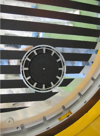
The small solar power sail demonstrator “IKAROS” (Kawaguchi et al., 2008; Mori et al., 2009) is a Japanese engineering verification spacecraft launched on May 21, 2010 at JAXA Tanegashima Space Center together with the Venus Climate Orbiter AKATSUKI (Planet-C). IKAROS stands for “Interplanetary Kite-craft Accelerated by the Radiation Of the Sun”. The weight of the IKAROS spacecraft is 307 kg, and the size is 1.58 m in diameter and 0.95 m in height. IKAROS has an extremely thin of 7.5 m polyimide membrane with 20 m in diameter as shown in figure 1. Reflecting the photons from the sun, this sail translates solar radiation pressure to the thrust of the spacecraft. This satellite rotates with the angular speed of about 1–2 rotation per minute (rpm) to keep spreading the sail with the centrifugal forces. The purpose of this mission is to demonstrate the solar-sail performance in the interplanetary space. After the launch, IKAROS successfully deployed the solar sail on June 9, 2010, and started sailing to Venus.
According to the current orbit design, IKAROS will pass Venus in half a year after the launch and go beyond 2 AU from the earth in about 2 years. During its cruising phase, GAP measures the gamma-ray polarization of the prompt emission of GRBs. We also determine the precise position of GRBs using the interplanetary network (IPN). In the following sections, we show a design of our gamma-ray polarimeter GAP, with its pre-flight and in-flight calibration data, and the numerical studies of the Geant 4 simulator.

2.2 Gamma-ray Burst Polarimeter : GAP
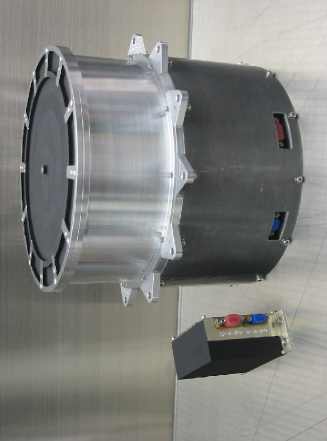
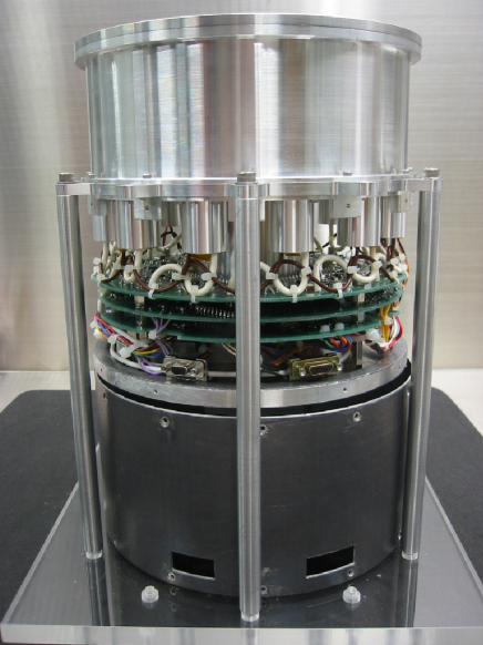
GAP is the “GAmma-ray bursts Polarimeter”, which consists of two components; the detector unit (GAP-S) and the power supply unit (GAP-P). GAP-S is a very small detector with 17 cm in diameter and also 16 cm in height as shown in figure 2. A small square box aside GAP-S is GAP-P which contains two DC-DC power converters for the electronics and two high-voltage modules with a function of current limiter. The weight of GAP-S and GAP-P is only 3.69 kg and 0.16 kg, respectively. The total power is about 5 W including both GAP-S and GAP-P. Hereafter we simply call this system “GAP”.
GAP is mounted on the bottom panel of IKAROS which always looks almost anti-solar direction. Therefore GAP always observe the deep universe during the cruising phase of IKAROS. The cylindrical detector cases (shassis), except for the detector top, are covered by thin lead sheets with 0.3 mm or 0.5 mm thickness to avoid the cosmic X- and gamma-ray background, intense soft X-ray transients, and solar flare events occurred behind GAP.
2.3 Design of GAP
The polarization detection principle of GAP is the angular anisotropy of the Compton scattering. The cross section of the Compton effect is due to the Klein-Nishina formula;
| (1) |
where, is the classical electron radius. The and values are the energies of the incident and the scattered gamma-ray photon, respectively. The denotes the scattering angle, and the means the azimuth angle measured from the polarization vector (electric field vector) of incident photon. The relation between and is well known as
| (2) |
Here, is the electron mass and is the speed of light in a vacuum. Assuming the non-relativistic case by substituting , the Klein-Nishina formula is approximately described as
| (3) |
The amplitude of the modulation is basically proportional to the function of in the plane. By detecting modulation curve from the astronomical phenomena, we can measure the linear polarization degree.
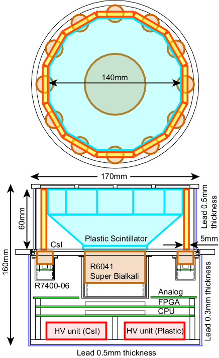
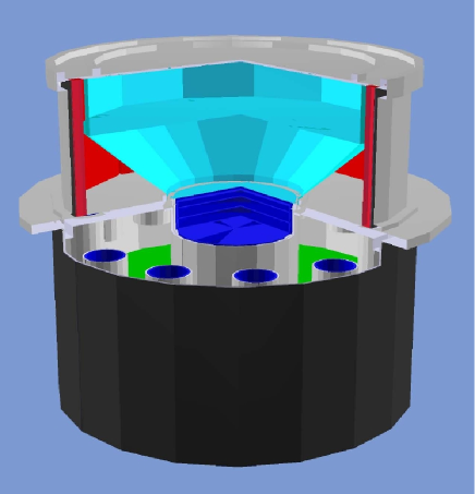
In figure 3, we show the basic concept of our gamma-ray polarimeter GAP. A dodecagon (twelve-sided polygon) plastic scintillator with a single non-position sensitive photo-multiplier tube: PMT (R6041 Hamamatsu Photonics ) is attached at the center, and 12 CsI scintillators with PMT (R7400-06 Hamamatsu Photonics ) are set around it. The photo-electric surface of R6041 is a super bialcari type, and its electrode structures are re-modeled to withstand the strong pyro-shock and vibration during the rocket launch. The central plastic works as the Compton scatterer, and the angular distribution of scattered photons coinciding with the plastic scintillator is measured by the surrounding CsI scintillators with the angular resolution of 30 degree each. We first considered a multi-anode PMT to know a scattering position for the central plastic to have a better sensitivity for polarization. However, in the developing phase of GAP, the multi-anode PMTs were known not to survive the strong shock and random-vibration environments at the rocket launch. Then we avoided the risk and adopted the advantage of high geometrical symmetry to reduce the fake modulation. All the PMTs were tested and passed the pre-flight qualification vibration levels of JAXA at the Industrial Research Institute of Ishikawa. We also passed the qualification shock test with 1000 Gsrs level at ISAS/JAXA.
We first designed the depth of the plastic as 7 cm for the pre-flight model (PFM) because it fully satisfies one Compton (Thomson) length to scatter photons of 100 keV, however to reduce the weight of GAP, the depth of the flight model (FM-GAP) is changed to 6 cm. Since the scattered photons should escape from the plastic and reach CsI, the radius of the plastic is also better to be shorter than one Thomson length. The CsI scintillators have to stop the scattered photons with high efficiency, we set their thickness as 5 mm whose stooping power is almost 100 % at 100 keV and about 60 % at 200 keV.
2.4 Brief Summary of Electronics and Data Acquisition System
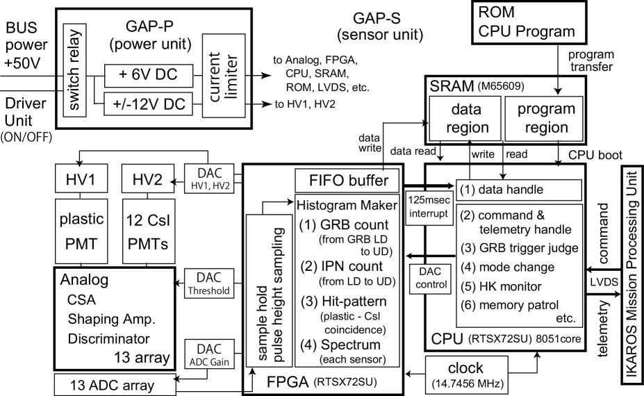
GAP has 13 analog outputs (1 plastic and 12 CsI scintillators). In figure 4, we show a flow chart of the readout circuit. These 13 signals are read out by 13 discrete analog electronics arrays. The standard streams are used in signal readout with preamplifiers, shaping amplifiers and discriminators are used. Once the gamma-ray photon is triggered by any PMT, analog signals of all PMTs are converted to digital signals with analog-to-digital converter, and the following FPGA reads all their digital values. Then, the FPGA analyzes all pulse heights within 5 sec timing window, and selects the plastic–CsI coincidence events as the polarization signals.
Every 125 msec, the FPGA interrupts the CPU processing and transfer the histogram data created by FPGA to CPU. The CPU edits the data type of lightcurve, spectra, and hit-pattern of polarization for each observation mode (see below). The edited data by CPU are transfered to the IKAROS Mission Processing Unit (MPU), and the data is stored as the telemetry packet in the mission data recorder.
The CPU also recognizes the commands and works as the human–GAP interface. It controls several Digital-to-Analog Converters together with FPGA. We can monitor House Keeping (HK) data such as temperature, voltage, current and simple light curves. We employed a memory patrol system with the majority logic in the CPU, so the single-bit memory error can be repaired by the CPU itself. This function reduces the probability of CPU hang-up and/or miss operations. GAP used radiation tolerant and MIL class ASICs for the core devices, such as FPGA, CPU, SRAM, LVDS but not for ROMs. Almost all key devices of the GAP circuit cleared two types of test such as 60Co gamma-ray irradiation and 200 MeV of proton irradiation to select the qualified devices at the Tokyo Metropolitan Isotope Research Center and at the Wakasa-Wan Energy Research Center.
When we switch the GAP power unit on, the CPU program written in the ROM device is transfered to the program region of the radiation tolerant SRAM. Then the CPU starts to work and the ROM device is switched off. The core of CPU is equivalent to the 8051 processor which is burned in the same FPGA device RTSX72SU. The observation data and the HK data are temporary stored in the data region of SRAM, and they are transfered to the IKAROS mission processing unit with the LVDS communication when the CPU gets the data request commands. Two high voltage modules are supplied from Meisei Electric Co.,Ltd, these are the same type used for the Suzaku and the Kaguya satellites of JAXA.
3 Observation Mode
The GAP has the calibration mode and 2 observation modes (GRB mode and CRAB mode). The onboard CPU is automatically monitoring the gamma-ray count rate in every one second. If the count rate suddenly increases above the preset value, the CPU switches its status to the GRB mode. The judge of a GRB trigger is performed with the increase of count rate between the energy range of GRB_LD and UD about 220 keV. Here, the GRB_LD is the lower discriminator level for the GRB judgement. We can set this GRB_LD for each sensor, and the nominal value is about for 12 CsI scintillators and for the plastic scintillator. We set this GRB_LD much higher than the sensor LD to avoid the noise fluctuations and also to avoid the intense soft X-ray transient, mainly solar flares.
3.1 Calibration Mode and onboard Calibration
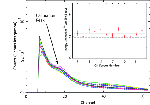
We mounted seven weak radio isotope sources of 241Am on the top panel of GAP, one for two CsI scintillators and one for the plastic at the center. The count rate of 241Am is about 10 Hz per CsI. In the calibration mode, we obtain the detail spectra with 64 energy channels for each sensor. Therefore we can measure the pulse height of line of 241Am with high precision. This spectral data contains only the single-hit photon events because the coincidence events, e.g. plastic–CsI and CsI–CsI, lose some of the energy and it is lower than 59.5 keV. Since the integration time can be chosen from 30 sec to 4.3 hours with 2 minuets steps, we can flexibly count up photons in the environment with any background rate, and avoid the buffer overflow.
In figure 5, we show 12 CsI spectra obtained in orbit. This spectra are equivalent to 5 hours integration (1 hour 5) after the careful gain adjustments. The 59.5 keV line of 241Am is clearly observed. The inserted panel in figure 5 shows the uniformity of the peak energy channel of the calibration line for each CsI sensor. The best fit line is 18.2 channel and two dashed lines show the upper and lower boundary of 2 % deviations from the best fit. We succeeded in adjusting 12 CsI gains within 2 % level. We, of course, monitor these gains once in every two weeks, and confirmed they are quite stable within the 2 % deviations during the first two months.
3.2 GRB Mode
Once the CPU switches to the GRB mode, CPU records the coincidence hit-pattern (polarization data), lightcurve, and spectrum during 176 seconds since the time of GRB trigger (). Then, the GAP’s ring buffer memory is frozen, and GAP-CPU also records the data of 16 seconds before the trigger ().
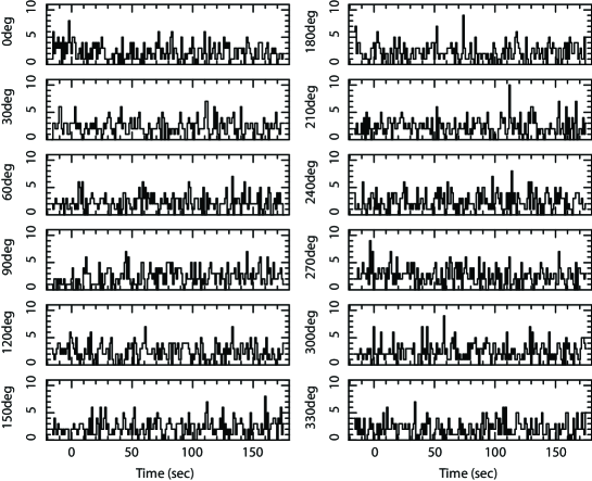
We can also start the GRB mode manually by sending a mode change command to get the background data in the manual GRB mode. The top panel shows lightcurve, spectrum and polarization (coincidence) data of the GRB mode in figure 6. We show the GRB lightcurve with the energy range between LD and UD, and it contains the data with two kinds of time resolution. In the first 32 second since the GRB trigger (), the lightcurve is recorded with the high time resolution of 125 msec, which is suitable for the interplanetary network (IPN) to determine the GRB direction together with other satellites. In the following 144 sec () and the 16 sec of pre-trigger (), the lighrcurves are recorded with 1 sec time resolution. At the same time, one integrated spectrum is obtained between the time interval of with 16 PHA channels as shown in figure 6 middle panel. This spectral data contains the photons of 12 CsI scintillators only with the single hit event. Figure 6 (bottom) is the summed polarization data of the low- and high-energy band as a function of phase angle, between the time interval of and in the manual GRB mode, respectively. There is no fake modulation seen in the angular distribution. This is the strong advantage of the geometrical symmetry of GAP’s configuration as shown in figure 3.
In figure 7, we show the lightcurves with the plastic–CsI coincidence events corrected for each angular phase in the manual GRB mode. Here we determined the phase angle as the CsI No.1 when the sun pulse signal comes from the spacecraft. When GAP enters the GRB mode, it starts measuring the polarization (hit-pattern of plastic–CsI) every one second. Therefore we are able to get the time resolved polarization data. GAP is always monitoring the rotation period of IKAROS, so this polarization lightcurve has been already corrected for its rotation phase in every 125 msec. The polarization is measured with 2 energy bands of High and Low. The energy range of the low-energy polarization is equivalent to the one between LD and HITPAT_LH. Similarly the high-energy polarization is measured between HITPAT_LH and UD. Here HITPAT_LH is the boundary channel of energy dividing the low- and the high-energy, and we can change HITPAT_LH with the command. The nominal value of HITPAT_LH is set about .
When the GRB trigger is set, the GAP-CPU latches the GRB trigger time (clock counter), and store it in the SRAM. GAP also memorizes the sun pulse time (phase) around the trigger time and the rotation period of the IKAROS spacecraft at that time. Therefore we can determine the phase angle (meridian) of the polarization vector around the IKAROS rotation axis. GAP also stores total photon counts of each phase angle (30 degree angular resolution) during the GRB mode, so we enable to determine very rough direction for bright GRBs.
| time | lightcurve | polarization | spectrum |
|---|---|---|---|
| (LD–UD) | (low:LD–HITPAT_LH) | (LD–UD) | |
| (high:HITPAT_LH–UD) | (16 channel) | ||
| 1 sec | 1 sec | N/A | |
| 125 msec | 1 sec | — | |
| 1 sec | 1 sec | — | |
| — | — | 176 sec |


3.3 CRAB Mode
We prepared the mode, which can continuously observe targets, named CRAB mode. This is essentially the mode for continuous monitoring of the Crab. Using the phase information of IKAROS’s rotation period measured with the sun pulse interval (approximately 1 rpm), GAP can stack the polarization data during this Crab mode. In Crab mode, GAP starts the integration of polarization data at the time when the CPU gets the sun pulse signal. Therefore the phase angle of polarization vector can be determined. Of course, when the count rate significantly increases and the GRB flag is happen during the CRAB mode, the CPU switches its status to the GRB mode.
According to the current plan of the IKAROS attitude, GAP will observe along the ecliptic plane, which crosses at the galactic plane near the galactic center and also at its opposite direction, very close to the Crab nebula. Thus we will spend 90 % of the observable time in the CRAB mode continuously, and we try to measure the polarization from any hard X-ray and gamma-ray objects in the field of view. The Crab itself is expected to be in our field of view within 10 degree from the GAP’s detector axis in the almost whole month of December, 2010. In this Crab mode, GAP obtains the spectrum of plastic scintillator, the summed spectrum of 12 CsI scintillator in 16 PHA channels, and polarization of 2 energy bands (LD–HITPAT_LH and HITPAT_LH–UD) with 24 angular resolution. The exposure of each Crab mode can be set from 30 sec to 8.5 hours, and we usually set the Crab mode with about 110 minutes integration.
We show two spectra in the Crab mode for the plastic and CsI detectors during the 110 minutes integration in figure 8. The Crab itself was out of the field of view. If GAP observes the sky without any strong X-ray/gamma-ray sources, these two spectra should be mainly explained by the Cosmic X-ray Background (CXB). The particle background was rejected by the UD of each scintillator and the multiple coincidence logic. However the GAP has the wide field of view, and observed the almost galactic center during the first two months since the GAP switch-on. Therefore these two spectra are the mixture of the CXB and the GC sources.
As shown in the bottom of figure 8, both modulation curves are flat. When we adopt the constant model, the fitting results of low- and high-energy band are with for 23 degrees of freedom and with for 23 degrees of freedom, respectively. Here the error is 90 % confidence level. The observed modulation is quite flat within 1 % level for the long integration of the CXB and GC sources in the Crab mode. This strongly supports the flatness of the GAP angular response for the non-polarized data.


4 Detector Capability Estimated by Geant 4 Simulation
In this section, we show Monte Carlo simulations with the Geant 4 simulator to estimate the capability of GAP and verify the model parameters. As shown in figure 9, we set a Geant-4 model of geometries and mass of elements which represents the real detector as precise as possible. The cylindrical aluminum cases of detector (light gray) are covered by thin lead sheets (dark gray) except for the top panel window to avoid the scattered photons from the spacecraft body. So the direct X-ray from the top direction illuminates the plastic and also the edge of the CsI. The plastic and 12 CsI scintillators are shown in light blue and red, respectively. The 13 PMTs are shown in blue and all of them are covered with thin aluminum cylinders. The green sheet inside the detector case represents the three layers of electric circuits. Two high voltage modules are also modeled while they are behind the detector case. Additionally, we consider a simplified spacecraft body with thick aluminum sheets (mass equivalent) as a scatterer in the geometry model (not appeared in figure 9). The outputs from this simulator are edited to the same type of informations observed by GAP. Moreover, to investigate the physical interaction between the incident gamma-ray photons and GAP, we also outputs higher order of informations such as spectrum of each sensor, coincidence spectrum of each sensor, polarization informations for single, double and multiple coincidence.
4.1 Modulation Factor, Efficiency and pre-flight calibration
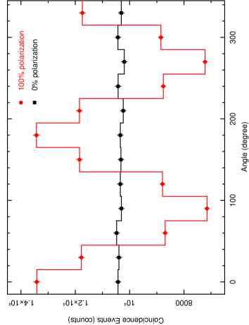
A value of modulation factor () is the key parameter to describe the detector sensitivity for the polarization measurement. The definition of the is the ratio of the amplitude to the average level of modulation curve of detector response for 100 % polarized gamma-ray. According to the cross section of the Compton effect in equation (1) and (3), the angular distribution of the scattering photon basically shows modulation. Figure 10 shows the simulated modulation curves when we assume the condition that the gamma-ray photons with 100 % polarization degree (open square) and non-polarization (filled square) are irradiated in front of GAP. The GAP’s modulation factor is estimated by the Geant 4 simulator as
| (4) |
Here, and is the maximum and minimum counts of the angular distribution of scattering photons.
4.2 Ground-base Calibration at KEK Photon Factory
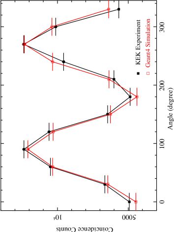
To verify the mass model and also check the logics in the Geant-4 simulator, we carried out the ground-based calibration using the Proto-Flight Model (PFM-GAP) before launch. The Flight Model (FM-GAP) was not ready to use at that time, so we used the PFM-GAP for the test on November 1–5, 2008 at KEK Photon Factory (beam line PF-14A). The only difference between FM-GAP and PFM-GAP is the thickness of the central plastic and height of CsI. The PFM-GAP is 7 cm in thickness and height, but we change the design of FM-GAP into 6 cm to reduce the weight of the FM system.
We tested a very limited number of parameters such as the modulation factor (MF) and also the detection efficiency (). The monochromatic 80 keV pencil beam of 0.8 mm in diameter with 82 % polarization was irradiated to the center of PFM. The beam is so narrow that we could not carry out the uniform irradiation on the top surface. The observed distributions of coincidence photons of the 12 CsI units are shown in figure 11 together with the Geant-4 simulation for the mass model. The black and red points are the result of KEK experiment and that of Geant-4 simulation by the experiment beam, respectively. Both curves agree well and strongly support the validity of the Geant-4 mass model for the PFM-GAP detector. The modulation factor for the 82 % polarized beam at the center position is by the experiment. This is equivalent to for the 100 % polarized beam irradiated to the center of PFM-GAP.
In figure 12, we show the modulation factor and an efficiency, which are calculated for the mass model of FM-GAP using the same logics of the PFM, as a function of photon energy in case of uniformly irradiated into the full surface of FM-GAP. The modulation factor for the FM-GAP is obtained as between 80–200 keV range, using the same mass model except for the thickness of the plastic and the height of CsI. In case of uniform irradiation on the top surface, this value is lower than the KEK pencil beam experiment. The efficiency (), which is defined as a ratio of the number of plastic–CsI coincidence events to the total incoming photons is very low of about 0.18 at around 100–150 keV. Since the depth and diameter of the plastic scintillator is optimized as 1 Compton length for 100 keV photon, the self-absorption reduces the efficiency and the modulation factor for the lower energy photon below 100 keV. The value of modulation factor at low-energy is also strongly influenced by the setting of LD () of plastic scintillator.

4.3 Minimum Detectable Polarization
Using the modulation factor () and the efficiency shown in figure 12, we estimate a rate of GRBs whose polarization is detected. We use the definition of minimum detectable polarization (MDP) as the sensitivity for the polarization measurement (e.g. Weisskopf et al. (2010)). The MDP is defined as
| (5) |
Here, the value is the significance of detection. If we assume 99 % confidence level, is generally used (Weisskopf et al., 2010). .
The detectability of polarization depends on the source flux (), the total duration () and the area of detector () for a GRB, that is to say a total number of photons. To estimate the MDP, we used a model of the brightness and duration distribution of CGRO-BATSE catalog of 50–300 keV range which is almost matching the energy coverage of GAP. If we assume a case that the polarization degree of GRBs shows about % level (Lazzati et al., 2004; Toma et al., 2009), we expect to detect the polarization with a rate of 2–4 GRBs/year above the 40 % degree of polarization. If a degree of polarization is lower than this, a chance of detection will be one or two a year.
4.4 Response for Polarized Beam of Diagonal Incident Photon
In figure 13, we show the detector response simulated by the Geant-4 for the incident photons from the diagonal direction. We assume the incident direction of deg from the detector axis of GAP, and the azimuth angle of deg. The top, middle and bottom panels show the response of polarization degree of %, respectively. We assume the polarization vector is parallel to the detector surface in these simulations.
In the case of %, the modulation curve basically depends on the . This is because the GAP surface looks like elliptic shape from the diagonal position. On the other hand, the modulation curve of polarized gamma-ray shows the composition of (see equation (2)) and by the response for the diagonal incident photons. As shown in the middle and bottom panels of figure 13, the modulation with two peaks will be observed for polarized gamma-rays, but the peak intensity is different from each other by the diagonal effect. Not to say, the position of the peak is also influenced by the vector of incident polarization.

5 First Detection of GRB
Since the switch-on of June 21, GAP detected the first GRB of GRB 100707A on July 7, 2010. The lightcurve is shown in figure 14. The trigger time is 00:47:22.878 UT with the uncertainty of sec at the distance of 17,917,783 km from the Earth. The direction of IKAROS from the Earth on July 7 is . The time accuracy will be improved to sec in near future after the careful calibration of clock system. This burst was also triggered by Fermi-GBM, Suzaku-WAM, Konus-Wind, and Messenger-GRN. Therefore the direction of GRB 100707A was determined by the interplanetary network (IPN). The error box of GRB direction by IPN is reported as by Hurley et al. (2010).
We have checked the consistency of our clock system to the reported IPN GRB direction. Cross-correlating the lightcurves between the IKAROS-GAP and Suzaku-WAM, the difference of arrival time of maximum photon flux between GAP and Suzaku-WAM is sec. Then the GRB position is calculated as the corn with the angle of degree from the direction of IKAROS. Here we assumed the error of angle is due to the time accuracy (0.250 sec) of GAP system. The estimated GRB direction is in 3 uncertainty which is consistent with . Therefore we conclude that GAP can join the IPN system, which consists of such as Fermi, Konus-Wind, Messenger-GRN and so on.
According to the IKAROS attitude, the axis of GAP direction is on July 7, 2010. Therefore, the incident direction of GRB 100707A is almost degree from the center of GAP field of view. In this case, the polarization measurement is quite difficult. According to the Konus-Wind results, the peak energy is (Golenetskii et al., 2010), and Fermi-LAT also detected this event (Pelassa et al., 2010), so the GRB 100707A was a hard and bright burst. This hard spectrum could enable GAP to detect this event even if the side cylinder and the bottom is shielded by the thin lead.

6 Summaries
-
1.
We developed the first gamma-ray burst polarimeter “GAP” aboard the small solar power sail demonstrator IKAROS.
-
2.
The IKAROS spacecraft was launched on May 21, 2010. We performed calibrations since the switch-on of June 21, 2010, and succeeded in setting all CsI gains within 2 %. After that we started GRB observation.
-
3.
The geometrical shape of GAP is highly symmetry, so the systematic uncertainty of fake modulation is about 1 % level for the CXB. The pre-flight calibration at KEK and the Geant-4 simulation, which is fully consistent, strongly support the validity of our detector. GAP measures the angular anisotropy of Compton scattering with real coincidence events between the plastic and 12 CsI scintillators. These two points are advantage for the gamma-ray polarimetry, and we will perform reliable observation for the gamma-ray polarization of GRBs, bright magnetar flares, and Crab nebula.
-
4.
According to the current operation, the detection rate of GRBs is about once a week. For the bright events, we can discuss the polarization degree. The rate of expectation to detect the polarization is 2–4 events a year if GRBs show about 40 % polarization as theoretical prediction.
-
5.
GAP will observes the gamma-ray polarization in the entire field of view with the Crab mode. We will measure the polarization degree or upper-limit along to the ecliptic plane, especially for the Crab nebula and the galactic center.
-
6.
We require informations about the GRB direction while we will contribute to the interplanetary network system soon.
Acknowledgments
We deeply thank the operations staffs at the Tokyo Metropolitan Industrial Technology Research Institute and Dr. Satoshi HATORI, Dr. Kyo KUME and technical staff at the Wakasa-Wan Energy Research Center for their assistances during the qualification tests of electrical devices. We also thank Mr. Takano at the Industrial Research Institute of Ishikawa for his support during the mechanical test. This work is supported in part by the Grant-in-Aid from the Ministry of Education, Culture, Sports, Science and Technology (MEXT) of Japan, No.20674002 (DY), No.18684007 (DY) and also this is supported by the Steering Committee for Space Science at ISAS/JAXA of Japan (TM).
References
- Amati et al. (2002) Amati, L., Frontera, F., Tavani, M, et al. 2002, A&A, 390, 81
- Amati et al. (2006) Amati, L., 2006, MNRAS, 372, 233
- Bellazzini et al. (2003) Bellazzini, R., Angelini, F., Baldini, L., et al., 2003, SPIE, 4843, 383
- Coburn & Boggs (2003) Coburn, W. & Boggs, S. E., 2003, Nature, 423, 415
- Costa et al. (1997) Costa, E., Frontera, F., Heise, J., et al., 1997, Nature, 387, 783
- Dean et al. (2008) Dean, A. J., et al., 2008, Science, 321, 1183
- Fenimore & Ramirez-Ruiz (2000) Fenimore, E. E., & Ramirez-Ruiz, E. 2000, astro-ph/0004176
- Ghirlanda et al. (2004) Ghirlanda, G., Ghisellini, G., Lazzati, D., 2004, ApJ, 616, 331
- Golenetskii et al. (2010) Golenetskii, S., Aptekar, R., Frederiks, D., et al., 2010, GCN, 10948
- Gunji et al. (1994) Gunji, S., Sakurai, H., Noma, M., et al., 1994, IEEE, 41, No.4
- Gunji et al. (1997) Gunji, S., Kudo, E., & Sakurai, H., 1997, IEEE, 41, No.4
- Gunji et al. (2007) Gunji, S., et al., 2007, SPIE, 6686, 18-1
- (13) http://jp.hamamatsu.com/en/index.html
- Hill et al. (2007) Hill, Joanne E.; Barthelmy, Scott; Black, J. Kevin, et al., 2007, SPIE, 6686, 66860Y
- Hurley et al. (2010) Hurley, K., Goldsten, J., 2010, GCN, 10947
- Kamae et al. (2008) Kamae, T., Andersson, V., Arimoto, M., et al., 2008, Astroparticle Physics, 30, 72
- Kawaguchi et al. (2008) Kawaguchi, J., Mori, O., Tsuda, Y., et al., 2008, Proceedings of 59th International Astronautical Congress, IAC-08.A3.6.15
- Kestenbaum et al. (1976) Kestenbaum, H. L., Cohen, G. G., Long, K. S., et al., 1976, ApJ, 210, 805
- Kishimoto et al. (2007) Kishimoto, Y.; Gunji, S.; Ishigaki, Y., et al., 2007, IEEE Trans. on Nucl. Sci. 54, 3, 561–566
- Kitamoto et al. (2010) Kitamoto, S., Murakami, H., Shishido, Y., et al., 2010, Review of Scientific Instruments, 81, 023105
- Lamb et al. (2004) Lamb, D. Q. et al. 2004, New Astron. Rev. 48, 423 (astro-ph/0309462)
- Lazzati et al. (2004) Lazzati, D., Rossi, E., Ghisellini, G, Rees, M. J., 2004, MNRAS, 347, L1
- McGlynn et al. (2007) McGlynn, S., Clark, D. J., Dean, A. J., et al., 2007, A & A, 446, 3, 895-904
- Mihara & Miyamoto (2004) Mihara, T., & Miyamoto, H., 2004, Proceedings of X-ray Polarimetry Workshop.
- Mori et al. (2009) Mori, O., Sawada, H., Hanaoka, F., et al., 2009, Transactions of the Japan Society for Aeronautical and Space Sciences, Space Technology Japan, Vol.7, No.ists26, pp.Pd87-Pd94
- Murakami et al. (2010) Murakami, T., Yonetoku, D., Gunji, S., et al., 2010, Proceedings of Gamma-Ray Burst Conference in Kyoto
- Norris et al. (2000) Norris,J., Marani, G.,& Bonnell, J. 2000, ApJ, 534, 248
- Rees & Meszaros (1992) Rees M. J. & Mészáros P., 1992, MNRAS, 258, L41
- Rutledge & Fox (2004) Rutledge, R. E.& Fox, D. B., 2004, MNRAS, 350, 4, 1288-1300
- Pelassa et al. (2010) Pelassa, V., Pesce-Rollins, M., et al., 2010, GCN, 10945
- Piran (1999) Piran, T., 1999, Physics Report, 314, 575
- Sakamoto et al. (2004) Sakamoto, T., Lamb, D. Q., Graziani, C., et al. 2004, ApJ, 602, 875
- Salvaterra et al. (2009) Salvaterra, R. et al., 2009, Nature 461, 1258-1260
- Schaefer et al. (2001) Schaefer, B. E., Deng, M. & Band, D. L. 2001, ApJ, 563, L123
- Suzuki et al. (2006) Suzuki, T., Gunji, S., Nakajima, R., et al., 2006, Japanese Journal of Applied Physics, 45, 1
- Swank et al. (2008) Swank, J., Kallman, T.,; Jahoda, K., 37th COSPAR Scientific Assembly. Held 13-20 July 2008, in Montr al, Canada., p.3102
- Tamagawa et al. (2006) Tamagawa, T., Hayato, A., Yamaguchi, Y., et al., 2006, SPIE, 6266, 62663W
- Tanimori et al. (2004) Tanimori, T., Kubo, H., Miuchi, K., et al., 2004, New Astron.Rev. 48, 263–268
- Tanvir et al. (2009) Tanvir, N. R. et al., 2009, Nature, 461, 1254–1257
- Toizumi et al. (2009) Toizumi, T., Nakamori, T., Kataoka, J., et al., 2009, AIP Conference Proceedings, Volume 1133, 85-87
- Toma et al. (2009) Toma, K., Sakamoto, T., Zhang, B., et al., 2009, ApJ, 698, 1042
- Weisskopf et al. (1976) Weisskopf, M. C., Cohen, G. G., Kestenbaum, H. L., et al., 1976, ApJ, 208, L125–L128
- Weisskopf et al. (2010) Weisskopf, M. C., Elsner, R. F., and O’Dell, S. L., 2010, arXiv:1006.3711v2
- Wigger et al. (2004) Wigger, C., Hajdas, W., Arzner, K. et al., 2004, ApJ, 613, 1088-1100
- Yonetoku et al. (2004) Yonetoku, D., Murakami, T., Nakamura, T., et al. 2004, ApJ, 609, 935
- Yonetoku et al. (2006) Yonetoku, D., Murakami, T., Masui, H., et al., 2006, SPIE, 6266, 86
- Yonetoku et al. (2009) Yonetoku, D., Murakami, T., Gunji, S., et al., 2009, Proceedings of X-ray Polarimetory in Rome