∎
Tel.: +43-1-4277 51210, Fax: +43-1-4277 9512 22email: markus.arndt@univie.ac.at 33institutetext: Herbert Gleiter 44institutetext: Institut für Nanotechnologie, Karlsruhe Institute of Technology, Karlsruhe, Postfach 36 40, 76021 Karlsruhe, Germany 55institutetext: Klaus Hornberger 66institutetext: Max Planck Institute for the Physics of Complex Systems, Nöthnitzer Str. 38, 01187 Dresden, Germany
New prospects for de Broglie interferometry
Abstract
We consider various effects that are encountered in matter wave interference experiments with massive nanoparticles. The text-book example of far-field interference at a grating is compared with diffraction into the dark field behind an opaque aperture, commonly designated as Poisson’s spot or the spot of Arago. Our estimates indicate that both phenomena may still be observed in a mass range exceeding present-day experiments by at least two orders of magnitude. They both require, however, the development of sufficiently cold, intense and coherent cluster beams. While the observation of Poisson’s spot offers the advantage of non-dispersiveness and a simple distinction between classical and quantum fringes in the absence of particle wall interactions, van der Waals forces may severely limit the distinguishability between genuine quantum wave diffraction and classically explicable spots already for moderately polarizable objects and diffraction elements as thin as 100 nm.
Keywords:
Foundations of quantum physics, matter waves, coherent optics, nanophysicspacs:
03.65.-w 03.75.-b 36.40.-c1 Introduction
Quantum physics ranks among our best-confirmed concepts of nature. And yet, a conceptual gap in the transition between quantum physics and classical observations has not yet been overcome. Matter wave interferometry with massive particles Broglie1923 has always been paradigmatic for the peculiar predictions of quantum physics as it demonstrates quantum delocalization and the superposition principle for material particles such as free electrons Hasselbach2010 , neutrons Rauch2000 , atoms Cronin2009 , dimers Bord'e1994 and complex molecules Arndt1999 during their unperturbed propagation.
Much of the pioneering work on matter wave interferometry is in particular associated with developments in neutron quantum optics. And in this issue we celebrate the birthdays and work of two central figures in research on the foundations of quantum physics, Helmut Rauch Rauch1974 and Daniel Greenberger Greenberger1983 . A number of recent advances both in the cooling of micromechanical oscillators (see collection in Aspelmeyer2008 ) and in matter wave manipulation methods Arndt1999 ; Brezger2002 ; Reiger2006 ; Gerlich2007 ; Arndt2009 now promise future extensions of experiments testing the superposition principle to much higher mass and complexity. In this paper we focus on two particularly simple concepts of particle interferometry, namely far-field diffraction behind a grating and near-field interference behind an opaque sphere or disk, i.e. the observation of Poisson’s spot. Recent developments of new nanoparticle sources Haberland1991 ; Deachapunya2008 ; Marksteiner2008 and novel detection methods Juffmann2009 may soon allow one to experimentally access them in a mass regime between and atomic mass units (amu).
Grating diffraction has already been thoroughly studied with electrons Jonsson1974 ; Freimund2001 ; Gronniger2005 , neutrons Gahler1991 , atoms Martin1988 ; Keith1991 ; Carnal1991 and molecules Chapman1995 ; Schollkopf1996 ; Nairz2001a ; Nairz2003 . The Poisson spot was observed with matter waves for the first time with electrons Komrska1971 ; Matteucci1990 and later extended to 1D diffraction behind a wire and 2D interference behind either a free disk or a zone plate using neutrons Kearney1980 ; Gahler1991 , atoms Nowak1998 ; Doak1999 and most recently also the diatomic molecule D2 Reisinger2009 .
In the following we assume quantum physics to be the correct theory for arbitrary particle size and mass, putting aside recently suggested modifications of standard quantum theory Diosi1989 ; Diosi2004 ; Penrose1996 ; Bassi2003 ; Wang2006 ; Carlip2008 ; Adler2009 . Instead, we ask which experimental constraints will in practice be limiting matter wave observations when the complexity of the particles grows.
The de Broglie wavelength of a particle at speed determines the size of the diffraction pattern. If the particle source is in contact with a thermal bath the most probable de Broglie wavelength will be related to the most probable particle velocity where the temperature is measured in Kelvin and is Boltzmann’s constant. Present-day interferometers are designed to deal with matter waves with wave lengths of about pm. This corresponds to a C60 fullerene with a mass of amu at m/s or equivalently to the gold cluster Au5000 with a mass of about amu and m/s. The latter is close to the thermal velocity at about 10 K and in reach of cryogenic buffer gas technologies inside a cold ion trap. In the following we compare the diffraction of C60 at a most probable velocity of 150 m/s, corresponding to a thermal beam at 900 K (case 1), to the case of Au5000 at v=1 m/s (case 2) . The polarizabilities are taken to be for C60 Berninger2007 and for the gold cluster Wang2006b .
2 Far-field matter wave diffraction
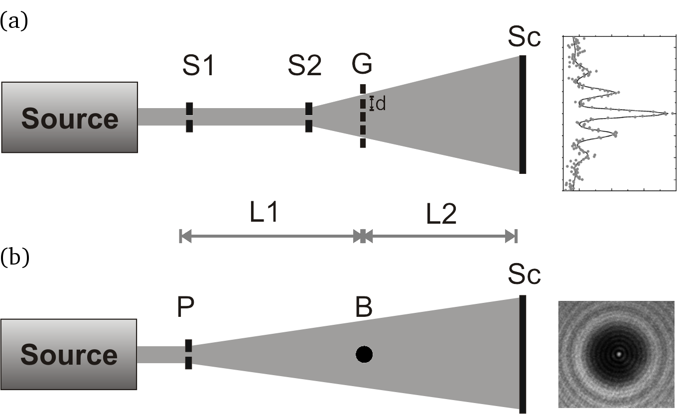
Far-field diffraction as depicted in Fig. 1(a) faces several requirements. First, the particles must be smaller than the grating period in order to neither get stuck in a material mask nor to average over neighboring potential wells in case of an optical diffraction grating. Second, both the beam diameter and its transverse coherence have to cover at least two slits, separated by the distance . This condition is met if the collimation angle of the molecular beam satisfies . We assume a symmetric setup, where the source of width acts as the first collimator, equal in width to a second collimation slit at a distance further downstream.
Mechanical nanogratings, with slit openings as tiny as 50 nm, periods of 100 nm are close to the smallest structures that can currently be made. Assuming a typical grating membrane thickness nm, the van der Waals interaction between the traversing molecules and the slit wall leads to a significant attractive force which results in the narrowing of the effective slit width Grisenti1999 ; Nairz2003 . Since the effect of this dispersion force grows with increasing polarizability and decreasing velocity , a particle may even be adsorbed by the surface if it approaches it within a cutoff distance Nimmrichter2008
| (1) |
This estimate is based on the asymptotic form of the Casimir-Polder potential, with the constant . In case 1, all fullerenes that approach the wall within 17 nm will be removed from the beam. For the Au5000 cluster (case 2) the cutoff distance amounts to already 46 nm. This reduction of the useful slit width indicates that there is a technical limit for grating diffraction. Ultra-thin membranes – made for instance from atomically thin graphene Geim2007 or nanometer-sized graphenoids Schnietz2009 – appear therefore very promising for future diffraction experiments if they are to be performed with material gratings. It is yet still necessary to show that such nanosheets can be prepared with the required accuracy and mechanical stability.
Optical absorption Reiger2006 or phase gratings Nairz2001a do not suffer from this limitation, but they are also intrinsically limited in their minimal period. Fluorine excimer lasers currently offer the shortest commercially available laser wavelength of . Even though shorter wavelengths will become available one day, a natural limit is set by the size of the interfering particle. For instance, a rhinovirus of amu has a diameter of 30 nm, which would be comparable to 40% of the grating period already at . And even for the densest metal clusters the density never exceeds kg/m3. A gold cluster with amu thus measures already 5.4 nm in diameter, i.e. about 7 % of the nm grating period produced by the mentioned excimer laser. Even though an optical grating would neither be clogged nor destroyed by an incident particle, the experienced effective potential will be smeared out if the particle size becomes comparable with or even larger than then grating period.
A further practical mass limit is given by the above mentioned collimation condition which can be expressed as a momentum condition. The transverse momentum must be smaller than the momentum kick imparted by the diffraction process:
| (2) |
Here and are the transverse and the longitudinal velocity, respectively, and is the transit time in the collimation stage between and .
This emphasizes the need for small transverse velocities , i.e. transverse cooling. While the cooling of atoms is an established laboratory technology, the cooling of clusters and molecules to below 1 K is still a challenge. A collimation to better than 10 rad corresponds already to a ratio between the transverse and the longitudinal temperature of .
In many current experiments, one therefore relies on selection rather than cooling.
According to Eq. (2) a reduction in will increase the mass limit, but at the expense of a reduction of the transmitted flux in proportion to . Also, increasing the flight time requires either a longer distance or a lower longitudinal velocity . But since the particle flux scales with and the diffraction of massive objects is bound to low signals.
At the right-hand side of Eq. 2 we replaced the longitudinal velocity by the most probable thermal speed. This equation leads to a mass limit of amu for a source temperature of 10 K and a collimation to rad, i.e. a transverse temperature of 1 nK. This corresponds to the parameters of the gold cluster. A source of appropriate intensity at this temperature still has to be demonstrated.
So far, our discussion included geometrical and kinematic arguments as well as the filtering of molecules in the presence of van der Waals forces. But also external or inertial forces can induce a fringe shift when they are oriented parallel to the grating vector. Their influence can be estimated using semiclassical arguments since, in the presence of conservative force fields, the shift of the beam envelope equals the displacement of the quantum interference pattern.
Gravity may cause a dispersive fringe shift: In a horizontally oriented beam experiment the grating bars will ideally be oriented parallel to the line of gravity g, however with an experimentally unavoidable misalignment angle . We require the gravitational shift of two contributing velocity classes and to be smaller than the separation of two interference fringes. This leads to the requirement
| (3) |
For the gold clusters this yields , implying that we require a collimation and maximal misalignment of better than for a practical experimental velocity bandwidth of . It should be noted, however, that at a velocity of 1 m/s and a flight distance of m the gravitational free fall distance would already amount to 20 m! This may still be feasible but it certainly poses a technological challenge. The falling time would be shortened by a factor of ten if we used ten times faster gold clusters with a ten times better collimation, i.e. rad. The falling distance would thus be reduced by a factor of one hundred to merely 20 cm. The collimation requirement of rad appears to be a formidable task as well, given our present-day technologies Hornberger2009 .
Also the rotation of the Earth shifts the interference patterns. We choose a coordinate system such that the angular frequency vector of the Earth is , where rad/s and specifies our geographical latitude. The Coriolis acceleration is given by ; if we orient the experiment vertically and such that and with grating bars aligned along , the Coriolis acceleration will point along the slits and the contrast will only be reduced by angular misalignments.
In order to quantify this effect we set and , where represents the angle between the molecular beam and gravity. We neglect the time dependence of v due to the Coriolis force. A double integration of over time yields the fringe shift. Here, we are only interested in the displacement along the grating vector, i.e.
| (4) |
While the first term describes the Coriolis shift along , the second term accounts for the finite alignment of the grating bars in relation to , where measures the angle between the grating bars and the x-direction. We require that the fringe shifts for different velocity classes should be smaller than one interference fringe, i.e. . Assuming a flight time of and the derivative with respect to leads us to the velocity selection criterion
| (5) |
With m, nm, , m/s and amu, we find that . This shows that the Coriolis force can be neglected even for a thermal molecular beam when the setup is aligned to better than rad.
To fulfill the combination of all requirements, i.e. collimation, velocity selection, orientation/alignment, high detection efficiency and source brilliance, for highly massive clusters is still a substantial challenge. We therefore proceed by illustrating an intermediate experiment in the mass range of around amu. Assuming the possibility of sublimation at a temperature of 600 K the de Broglie wavelength would still reach pm at a most probable velocity of 18 m/s. When collimating the beam to rad on the screen by two slits with a width of m separated by a distance m it should still be possible to identify two neighboring diffraction orders, separated by the diffraction angle rad. The transverse coherence width then reaches 175 nm at the location of the second collimator, where the nm diffraction grating is placed; this is sufficient for a genuine double slit experiment. We choose the distances m and find a total transit time of ms, corresponding to a falling distance in the gravitational field of cm.
A molecular flux of cm-2s-1sterad-1 would be required to finally detect individual molecules on the screen. Here we assume the source and collimator slits to be m high, and take the accumulation time and the grating transmission to be s and , respectively. Starting from a thermal velocity distribution, the beam intensity will further be reduced by the required velocity selection, i.e. by about .
3 Poisson’s spot
The problem of small de Broglie wavelengths and low source intensities can often be alleviated in near-field diffraction experiments, where beam coherence and geometrical requirements are usually less demanding than in the far-field. Near-field effects comprise various phenomena, from diffraction at an edge Gahler1991 , a grating Chapman1995a ; Nowak1998 or a circular obstacle Reisinger2009 –up to the Talbot-Lau interferometry in an arrangement of two or three gratings Brezger2002 ; Patorski1983 ; Clauser1994 ; McMorran2009 . Here we focus on the diffraction pattern behind a radially symmetric obstacle of radius , such as a disc or a sphere, that is illuminated by a point-like wave source Harvey1984a ; Lucke2006 . The most prominent feature here is the appearance of a bright spot (Poisson’s spot) in the center of the shadow region behind the obstacle, which is related to wave-like diffraction at the obstacle boundaries.
At a first glance it appears appealing to use this effect to demonstrate the wave-particle duality for very massive particles, as the mere existence of intensity in the dark field could be interpreted as an indicator of the particle’s wave nature. A second glance reveals, however, that the dispersive interaction between the particles and the obstacle walls must be taken into account. In particular, the presence of van der Waals forces can significantly obscure the spot even for neutral particles when they have a large polarizability. At the same time the attraction to the obstacle walls alone may already also explain the appearance of a bright spot in the dark-field, even if we take polarizable clusters to behave like billiard balls following classical Newtonian mechanics. Our following theoretical treatment transcends earlier methods for near-field Poisson patterns Dauger1996a in that it now includes, for the first time quantitatively, the attractive interaction.
The geometry of the setup is sketched in Figure 1b. The beam is directed along the -axis, with the points , , and defining the -planes of the source, the obstacle, and the detection screen, respectively. A circular pinhole of radius represents the source which emits a beam of particles with a collimation angle towards an opaque obstacle of radius at the distance . We are interested in the spatial density of the particles another distance further downstream, as a function of the dimensionless screen coordinate . In the paraxial approximation the size of both the source and the obstacle are taken small compared to the distances, , and the beam is well collimated, . The diffraction pattern of a monochromatic particle beam with the de Broglie wavelength is then given by
| (6) |
with defined in (7), as follows from a phase-space description similar to Hornberger2004 ; Nimmrichter2008 . It is normalized to the constant density of particles on the screen that would be observed in the absence of an obstacle, . We introduce the dimensionless parameters and , the main quantities characterizing the dimensionless amplitude function
| (7) |
It contains the Bessel function of the first kind and a phase related to the interaction between the particles and the obstacle (see below). In the absence of the van der Waals interaction the diffraction pattern associated with a point source at the origin reads Harvey1984a . The integral in the amplitude function (7) can be evaluated numerically by exploiting the exact result for when the lower integral bound is extended to zero.
3.1 The ideal Poisson spot
In Fig. 2(a) and Fig. 2(b), we plot the radial profile of the rotationally symmetric interference pattern (6) for and , respectively, for a symmetric experimental setup, i.e. . The dotted line depicts the expected classical shadow profile which would be observed in the absence of diffraction. Its shadow region has a radius of on the screen. The diffraction pattern exhibits a wavelike behavior with wide interference fringes for small , while it approaches the classical shadow profile for large , i.e. in the ’classical limit’ at finite distances from the symmetry axis. However, one can always observe an intensity peak at in the center of the classical shadow region. The spot is as bright as the classically expected intensity outside the shadow region, , independently of the setup geometry and the de Broglie wavelength. It is only the width of the spot that depends on both the wavelength and the geometry. The radius of the central spot is determined by the first zero of the Bessel function in (7), which yields . Consequently, the successful observation of the spot requires only that its width be smaller than the width of the classical shadow , which results in the rather lax condition . The condition is met exactly in Fig. 2(a), and by a factor of in 2(b). In a setup with an obstacle radius of nm and cm, the two plotted cases cover a range of de Broglie wavelengths of to pm.
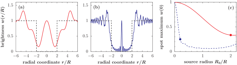
At first glance one might therefore think that no velocity selection is needed. This advantage, however, must be put into perspective as we have assumed an idealized point source, where the spot maximum is always , regardless of the incident de Broglie wavelength. In a real physical situation, the source has a finite extension and the spot is washed out because of the averaging over the source aperture, as described by Equation (6). This renders the height of the central spot wavelength-dependent. The reduction of the spot maximum as a function of the source radius is plotted in Figure 2(c) for the cases of 2(a) (solid line) and 2(b) (dashed line). In the latter case, where the wave length is five times smaller, the spot vanishes more rapidly because it is narrower than in the former case. The spot starts to get lost in the background as soon as it is averaged over more than its width on the screen. Plugging this into Equation (6) we can estimate a condition for the source radius at which a pronounced Poisson spot can still be observed Lucke2006 ,
| (8) |
The values given by this estimate are marked by full dots in Fig. 2(c). One notes from Eq. (8) that a larger distance between source and obstacle allows for larger source extensions. However, the particle beam intensity decreases quadratically with , which limits the possible source distance in practice. The distance to the screen , on the other hand, determines the width of the ideal Poisson spot through . In the plotted examples we set cm. For (corresponding to pm) one still obtains a pronounced central peak for a source pinhole radius of nm, as demonstrated by the solid line in Fig. 2(c). At the same time, the spot is strongly smeared out for (dashed line, corresponding to pm).
Although the condition (8) resembles the limit for the collimation slit aperture of a far-field interferometer, whith the obstacle radius playing the role of the grating period , the collimation requirements for a Poisson spot experiment are much less stringent than in the far-field case. The diffraction pattern (6) is in fact independent of the collimation angle , provided that it lies within the range . The much stricter collimation requirement of the far-field setup is therefore relaxed in practice, which is an advantage of the Poisson spot scheme, as has been demonstrated in Reisinger2009 . In case of a realistic particle beam with a finite longitudinal coherence, one should keep in mind that the diffraction pattern (6) must also be averaged over the distribution of de Broglie wavelengths .
Ultimately, the admissible pinhole radius of the source is bounded by to ensure that there is a shadow region at all, where the Poisson spot may emerge. This observation of particles in a classically forbidden area on the screen would thus be a clear indication of matter wave diffraction, provided we could neglect all particle-wall interactions.
3.2 Influence of the particle-obstacle interaction
A complete discussion of the mass limitations of Poisson’s spot has to include the effect of the dispersive interaction between the diffracted particles and the obstacle’s surface. In fact, the ideal spot pattern discussed so far can only be observed with light, fast and weakly polarizable particles such as atoms and D2 molecules Reisinger2009 . The interaction potential between a highly polarizable nanoparticle and the radially symmetric obstacle, however, is not negligible anymore. In our case of a well collimated beam and a small obstacle dimension we can account for it by introducing the eikonal phase term Nimmrichter2008 , which modulates the diffraction pattern through the amplitude function (7). The interaction is here approximated by a Casimir-Polder-type attractive potential which diverges at the obstacle wall. As a consequence, the obstacle is effectively enlarged from to because particles passing the obstacle at a distance smaller than will hit the wall and be adsorbed. A good estimate for is obtained from the minimal classical impact parameter that still yields an asymptotically outgoing trajectory of a particle impinging upon the obstacle plane parallel to the -axis Landau1960 ; Nimmrichter2008 .
We start by considering the diffraction at a nanosphere since such obstacles can be fabricated with a surface smoothness on the atomic level BritishBiocell2010 . Taking a metallic sphere of radius in the range of a few hundred nanometers, positioned at , we approximate the interaction by the asymptotic Casimir-Polder potential with an infinite wall mostepanenko-casimir spanned by the tangential plane on the surface of the sphere
| (9) |
Here, the Casimir parameter is the same as used in the far-field discussion of Sect. 2. While the computation of the exact Casimir-Polder potential in this geometry requires advanced numerical treatments PhysRevA.81.030502 , our approximation (9) is conservative since it overestimates the interaction strength at distances from the sphere surface—as the sphere bends away from the particle trajectory.
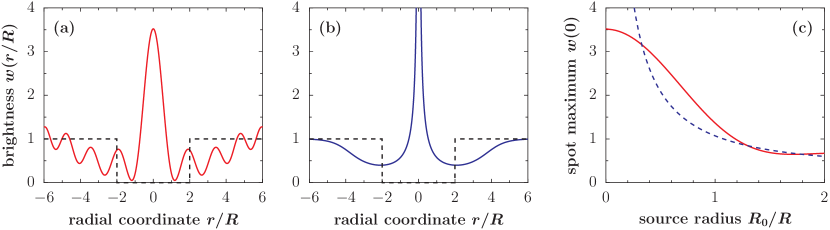
Figure 3(a) depicts the Poisson spot of a point source if the dispersion interaction is taken into account. The geometry parameters and are the same as in the ideal case of Fig. 2(a), but we now apply our potential model for a spherical obstacle attracting and diffracting a Au100 cluster with a mass of amu and a polarizability of Å3. The dashed line in the plot marks the shadow projection of the obstacle. We note that the maximum of the Poisson spot clearly increases with growing attraction, when compared to the ideal case.
What might look like a benefit at first glance, is relativized by plot (b) where we show the intensity distribution predicted by a classical deflection model. It was computed using the classical analogue of the eikonal phase approximation Hornberger2004 ; Nimmrichter2008 . The deflection is modeled by an instantaneous and radially inward directed momentum kick . The plots show that for highly polarizable particles a purely classical reasoning suffices to explain a spot-like intensity accumulation in the center of the screen. In fact, the depicted classical intensity distribution caused by a point source exhibits a -like divergence, which is related to the radial symmetry and is compensated by the area element in the course of any integration over a finite area around the origin.
The assessment of such a Poisson spot experiment therefore requires a careful quantitative analysis of the measured intensity on the screen in order to rule out a classical alternative for the expected experimental data. This problem is aggravated with growing particle size and polarizability. In addition, the classical and the quantum description become even less distinguishable with growing source radius. This is demonstrated in part (c) of Fig. 3, where the height of the central spot in the quantum (solid line) and in the classical (dashed line) case is shown as a function of the source radius in units of the obstacle radius. In such a regime the observation of a central spot can no longer be used as an indicator for the quantum wave nature. Instead of restricting the analysis to the central spot, one could alternatively take the outer intensity oscillations as a quantum signature in an experiment. These are, however, less pronounced and more easily averaged out over both a finite velocity distribution of the particles and an extended source. Even if the quantum and the classical case coincide, the setup may still serve as a van-der-Waals lens for particle beams.
For the plots (d)–(f) in the lower panel of Figure 3 the spherical obstacle has been replaced by a metallic disc of thickness nm. The interaction is now approximated by the Casimir-Polder potential of an infinite plane acting on the particle during the time of flight past the disc. Since the accumulated phase is now smaller than in the case of a spherical obstacle, a lower Poisson spot is found in (d) compared to (a). With such a thin disc obstacle the quantum interference effect is clearly distinguishable from the classical deflection model, as demonstrated in (f). Even for a realistic source radius nm the quantum spot visibility exceeds its classical counterpart significantly.
For even heavier particles than the Au100 clusters discussed here, as well as for larger -values, the classical deflection of the particle trajectories may no longer be approximated by an instantaneous momentum kick. Also in the quantum case the eikonal approximation ceases to be valid and must be replaced by a more complicated semiclassical scattering transformation Nimmrichter2008 .
Finally we note that, apart from being altered by the dispersion force close to a surface, the quality of the Poisson spot is also influenced by the surface roughness of the obstacle. In the deuterium diffraction experiment reported in Reisinger2009 the surface roughness of the disc dominated the influence of the interaction potential and led to a significant diminuition of the spot. However, modern microfabrication techniques as well as the strong interaction of the large nanoparticles considered here allow us to neglect the effects of surface corrugations. In the setting of Fig. 3, where Au100 clusters with a velocity of m/s are diffracted at a sphere (or disc) of radius nm, the effective enlargement of the obstacle radius by the cut-off (particle capture) distance is as large as nm, or nm in case of the disc. This exceeds by far the surface roughness of spheres or discs whose corrugations can nowadays be kept on the Angstrom level BritishBiocell2010 .
4 Conclusions
In summary, our discussion shows that a straightforward extrapolation of conceptually simple ideas such as far-field diffraction at a grating or the observation of Poisson’s spot behind a spherical or disc-shaped obstacle leads to non-trivial experimental challenges and may require a careful assessment of what can be observed. A number of dephasing agents, such as gravity, the rotation of the earth and – more than anything else – the influence of particle-wall interactions have a strong and usually contrast-limiting influence. Our analysis shows, however, also that present-day experiments are still far from any fundamental limit. Although other experimental arrangements may be better adapted for pushing the ultimate mass and complexity limits of matter wave interferometry Reiger2006 ; Gerlich2007 , we still envisage many interesting experiments in far-field diffraction and in observing Poisson’s spot with large clusters and molecules, in particular also with the foreseeable advent of new nanofabrication techniques for ultra-thin diffractive elements.
Acknowledgements.
We acknowledge support through the ESF program EuroQuasar MIME and the FWF project Z149-N16. MA and KH acknowledge fruitful discussions with Bodil Holst, University of Bergen.References
- (1) L. de Broglie, Nature 112, 540 (1923)
- (2) F. Hasselbach, Rep. Prog. Phys. 73, 016101 (2010)
- (3) H. Rauch, A. Werner, Neutron Interferometry: Lessons in Experimental Quantum Mechanics (Oxford Univ. Press, 2000)
- (4) A.D. Cronin, J. Schmiedmayer, D.E. Pritchard, Rev. Mod. Phys. 81, 1051 (2009)
- (5) C.J. Bordé, N. Courtier, F. du Burck, A.N. Goncharov, M. Gorlicki, Phys. Lett. A 188, 187 (1994)
- (6) M. Arndt, O. Nairz, J. Voss-Andreae, C. Keller, G.V. der Zouw, A. Zeilinger, Nature 401, 680 (1999)
- (7) H. Rauch, W. Treimer, U. Bonse, Phys. Rev.A 47, 369 (1974)
- (8) D. Greenberger, Reviews of Modern Physics 55, 875 (1983)
- (9) M. Aspelmeyer, K. Schwab, New Journal of Physics 10, 095001 (2008)
- (10) B. Brezger, L. Hackermüller, S. Uttenthaler, J. Petschinka, M. Arndt, A. Zeilinger, Phys. Rev. Lett. 88, 100404 (2002)
- (11) E. Reiger, L. Hackermüller, M. Berninger, M. Arndt, Opt. Comm. 264, 326 (2006)
- (12) S. Gerlich, L. Hackermüller, K. Hornberger, A. Stibor, H. Ulbricht, M. Gring, F. Goldfarb, T. Savas, M. Müri, M. Mayor, M. Arndt, Nature Phys. 3, 711 (2007)
- (13) M. Arndt, K. Hornberger, in Quantum Coherence in Solid State Systems, Proceedings of the International School of Physics “Enrico Fermi”, Course CLXXI, vol. 171, ed. by B. Deveaud-Plédran, A. Quattropani, P. Schwendimann (Società Italiana di Fisica, 2009), Proceedings of the International School of Physics “Enrico Fermi”, Course CLXXI, vol. 171, pp. 103–130
- (14) M.M. Haberland, H.Karrais, Z. Phys. D 20, 413 (1991)
- (15) S. Deachapunya, P.J. Fagan, A.G. Major, E. Reiger, H. Ritsch, A. Stefanov, H. Ulbricht, M. Arndt, Eur. Phys. J. D 46, 307 (2008)
- (16) M. Marksteiner, P. Haslinger, H. Ulbricht, M. Sclafani, H. Oberhofer, C. Dellago, M. Arndt, J. Am. Soc. Mass. Spectrom. 19, 1021 (2008)
- (17) T. Juffmann, S. Truppe, P. Geyer, A.G. Major, S. Deachapunya, H. Ulbricht, M. Arndt, Phys. Rev. Lett. 103, 263601 (2009)
- (18) C. Jönsson, D. Brandt, S. Hirschi, Am. J. Phys. 42, 4 (1974)
- (19) D.L. Freimund, K. Aflatooni, H. Batelaan, Nature 413, 142 (2001)
- (20) G. Gronniger, B. Barwick, H. Batelaan, T. Savas, D. Pritchard, A. Cronin, Appl. Phys. Lett. 87, 124104 (2005)
- (21) R. Gähler, A. Zeilinger, Am. J. Phys. 59, 316 (1991)
- (22) P. Martin, P. Gould, B. Oldaker, A. Miklich, D. Pritchard, Physica-B-&-C. 151, 255 (1988)
- (23) D.W. Keith, C.R. Ekstrom, Q.A. Turchette, D.E. Pritchard, Phys. Rev. Lett. 66, 2693 (1991)
- (24) O. Carnal, A. Faulstich, J. Mlynek, Applied-Physics-B B53, 88 (1991)
- (25) M.S. Chapman, C.R. Ekstrom, T.D. Hammond, R.A. Rubenstein, J. Schmiedmayer, S. Wehinger, D.E. Pritchard, Phys. Rev. Lett. 74, 4783 (1995)
- (26) W. Schöllkopf, J. Toennies, J. Chem. Phys. 104, 1155 (1996)
- (27) O. Nairz, B. Brezger, M. Arndt, A. Zeilinger, Phys. Rev. Lett. 87, 160401 (2001)
- (28) O. Nairz, M. Arndt, A. Zeilinger, Am. J. Phys. 71, 319 (2003)
- (29) J. Komrska, Advances in Electronics and Electron Physics (Academic, New York, 1971), pp. 139–234
- (30) G. Matteucci, Am. J. Phys. 58, 1143 (1990)
- (31) P.D. Kearney, A.G. Klein, G. Opat, R. G hler, Nature 287, 313 (1980)
- (32) S. Nowak, N. Stuhler, T. Pfau, J. Mlynek, Phys. Rev. Lett. 81, 5792 (1998)
- (33) R.B. Doak, R.E. Grisenti, S. Rehbein, G. Schmahl, J.P. Toennies, C. Wöll, Phys. Rev. Lett. 83, 4229 (1999)
- (34) T. Reisinger, A. Patel, H. Reingruber, K. Fladischer, W. Ernst, G. Bracco, H. Smith, B. Holst, Phys. Rev. A 79, 53823 (2009)
- (35) L. Diosi, Phys. Rev. A 40, 1165 (1989)
- (36) L. Diosi, Braz. J. Phys. 35 (2004)
- (37) R. Penrose, Gen. Rel. Grav. 28, 581 (1996)
- (38) A. Bassi, G. Ghirardi, Phys. Rep. 379, 257 (2003)
- (39) C. Wang, R. Bingham, J.T. Mendonca, Class. Quant. Grav. 23, L59 (2006)
- (40) S. Carlip, Class. Quantum Grav. 25, 154010 (2008)
- (41) S.L. Adler, A. Bassi, Science 325, 275 (2009)
- (42) M. Berninger, A. Stéfanov, S. Deachapunya, M. Arndt, Phys. Rev. A 76, 013607 (2007)
- (43) J. Wang, M. Yang, J. Jellinek, G. Wang, Phys. Rev. A 74, 023202 (2006)
- (44) R.E. Grisenti, W. Schöllkopf, J.P. Toennies, G.C. Hegerfeldt, T. Köhler, Phys. Rev. Lett. 83, 1755 (1999)
- (45) S. Nimmrichter, K. Hornberger, Phys. Rev. A 78, 023612 (2008)
- (46) A. Geim, K. Novoselov, Nature materials 6, 183 (2007)
- (47) M. Schnietz, A. Turchanin, C. Nottbohm, A. Beyer, H. Solak, P. Hinze, T. Weimann, A. Gölzhäuser, Small 5, 2651 (2009)
- (48) K. Hornberger, S. Gerlich, H. Ulbricht, L. Hackermüller, S. Nimmrichter, I. Goldt, O. Boltalina, M. Arndt, New J. Phys. 11, 043032 (2009)
- (49) M.S. Chapman, C.R. Ekstrom, T.D. Hammond, J. Schmiedmayer, B.E. Tannian, S. Wehinger, D.E. Pritchard, Phys. Rev. A 51, R14 (1995)
- (50) K. Patorski, Opt. Act. 30, 745 (1983)
- (51) J.F. Clauser, S. Li, Phys. Rev. A 49, R2213 (1994)
- (52) B.J. McMorran, A.D. Cronin, New J. Phys. 11, 033021 (2009)
- (53) J. Harvey, J. Forgham, Am. J. Phys 52, 243 (1984)
- (54) R. Lucke, Eur. J. Phys. 27, 193 (2006)
- (55) D. Dauger, Computers in Physics 10, 591 (1996)
- (56) K. Hornberger, J.E. Sipe, M. Arndt, Phys. Rev. A 70, 53608 (2004)
- (57) L.D. Landau, E.M. Lifshitz, Classical mechanics (Pergamon Press, Oxford, 1960)
- (58) B. Biocell, Archway house, cardiff uk, info@bbigold.com
- (59) V.M. Mostepanenko, N.N. Trunov, The Casimir effect and its applications (Clarendon, Oxford, 1997)
- (60) S. Zaheer, S.J. Rahi, T. Emig, R.L. Jaffe, Phys. Rev. A 81, 030502 (2010)