Theory of quantum dot spin-lasers
Abstract
We formulate a model of a semiconductor Quantum Dot laser with injection of spin-polarized electrons. As compared to higher-dimensionality structures, the Quantum-Dot-based active region is known to improve laser properties, including the spin-related ones. The wetting layer, from which carriers are captured into the active region, acts as an intermediate level that strongly influences the lasing operation. The finite capture rate leads to an increase of lasing thresholds, and to saturation of emitted light at higher injection. In spite of these issues, the advantageous threshold reduction, resulting from spin injection, can be preserved. The ”spin-filtering” effect, i.e., circularly polarized emission at even modest spin-polarization of injection, remains present as well. Our rate-equations description allows to obtain analytical results and provides transparent guidance for improvement of spin-lasers.
pacs:
42.55.Px, 78.45.+h, 78.67.De, 78.67.HcI Introduction
Experiments on semiconductor spin-lasers have demonstrated the potential of spintronics to go beyond the limits of devices relying solely on the carrier charge. Žutić et al. (2004); Rudolph et al. (2005); Holub et al. (2007); Hövel et al. (2008) These structures offer a practical path to realize spintronic devices, which could be useful for communications and signal processing, rather than limited to magnetoresistive effects. Spin injection into lasers is implemented optically, when circularly polarized light imparts the photons’ angular momentum to the spin of carriers,Meier and Zakharchenya (1984); Fabian and Žutić (2008); *Lu2009 or electrically, when a magnetic contact polarizes carriers entering the semiconductor.Žutić et al. (2004) Apart from the successful early demonstration of a spin-laser based on a bulk-like layer of GaAs,Ando et al. (1998) most experiments in this field concentrated on structures with quantum well (QW) active regions, using optical pump, Hallstein et al. (1997); Rudolph et al. (2003, 2005); Fujino et al. (2009) electrical injection Holub et al. (2007) or a combination of both.Hövel et al. (2008); Gerhardt et al. (2010) Recently, however, an (In,Ga)As/GaAs quantum dot (QD) spin-laser with electrical injection has been demonstrated, lasing at temperatures 100 K higher than its QW counterparts.Basu et al. (2008) QDs close a succession of reduced-dimensionality structures: quantum wells and wires, which have replaced bulk-like active regions of semiconductor lasers.Alferov (2001); *Arakawa1982:APL They allow to control the number and spin of carriers, as well as the quantum-confinement geometry. Abolfath et al. (2008); *Maximov2000:PRB A quantum dot spin-laser combines the potential of spin-polarized injection with the advantages of a QD-based active region, such as low threshold, robust temperature performance, and narrow gain spectra.Asryan and Suris (2002); Sellers et al. (2004) In addition to these properties of conventional (spin-unpolarized) QD lasers, the long spin relaxation times,Fabian et al. (2007) characteristic for QDs, are advantageous for spin-lasers.
Spin-dependent effects in semiconductor lasers were studied at various levels of complexity.[][Thisseminalworkincludedspin-relatedeffectsfor$P_Jn=0$; assumingthatthe(typicallyverydifferent)electronandholespinrelaxationtimesareidenticaltoeachother.]SanMiguel1995:PRA Dyson and Adams (2003); Vurgaftman et al. (2008); Basu et al. (2009) A transparent rate-equations (RE) approach to QW-based lasers has allowed to elucidate main consequences of the spin-polarized injection.Gøthgen et al. (2008) An important finding of this QW model is that the injection threshold , characterizing spin-unpolarized lasers, splits into two thresholds, , when the injected carriers are spin polarized. When injection reaches (majority threshold), the laser starts to emit photons with one helicity (circular polarization), the other helicity joining at , at which minority-spin electrons reach the threshold density. Both experimentsRudolph et al. (2003, 2005); Holub et al. (2007) and theoryVurgaftman et al. (2008); Gøthgen et al. (2008) have demonstrated an important advantage of the spin-lasers over the unpolarized ones: , assuming that all other parameters are identical. The threshold reduction,
| (1) |
would be largest for fully spin-polarized electrons with infinite spin relaxation time, reaching as much as .Gøthgen et al. (2008) According to the model, for any injection in the to interval, the laser acts as a ”spin-filter”, i.e., it emits circularly polarized light, even if the spin polarization of injected carriers is small. The relative width of this interval,
| (2) |
increases with the injected spin polarization. The ”filtering” effect is another merit of spin-lasers, as it offers new opportunities for their dynamic operation. Modulation of injected spin polarization was shown to modulate the intensity of laser emission, even at a constant total injection, and to increase the modulation bandwidth.Lee et al. (2010)
So far, theoretical description of spin-lasers has been essentially limited to QW-based models. To find distinguishing features of QD spin-lasers, in this work we formulate a model, which allows for analytical results and offers a direct comparison with the previous results for the QW spin-lasers. Rudolph et al. (2003, 2005); Holub et al. (2007); Gøthgen et al. (2008); Lee et al. (2010) Here, we focus on the parameters motivated by the experiments on (In,Ga)As-based QD spin-lasers,Basu et al. (2008, 2009),[Spin-dependentpropertiesof(In; Ga)AsQDshavebeenextensivelystudied; e.g.see; ][.(In; Ga)AshasbeenfrequentlyusedforconventionallaserswithQWorQDactiveregions; seee.g.; I.Tangring; H.Q.Ni; B.P.Wu; D.H.Wu; Y.H.Xiong; S.S.Huang; Z.C.Niu; S.M.Wang; Z.H.Lai; andA.Larsson; Appl.Phys.Lett.91; 221101(2007).]Yakovlev:2008. It is, however, instructive to consider other possible materials for spin QW and QD lasers, since a variety of active regions has been used for their conventional (spin-unpolarized) counterparts. This choice can be guided by long spin relaxation time for electrons, which enhances the desirable spin-laser characteristics.Oestreich et al. (2005) Longer spin relaxation times can result, for example, from a reduction of spin-orbit coupling, one of the main sources of spin relaxation.Žutić et al. (2004); Fabian et al. (2007) This can be achieved by choosing materials with light elements or by using different growth orientation in QWs.[Amorethanten-foldincreaseinspinrelaxationtimeispossiblebyreplacing(001)by(110)GaAs-basedQW:]Fujino2009:APL Long spin relaxation times have been reported in CdSe/ZnSe (an example of a II-VI structure) self-organized QDs.Klochikhin et al. (2008) Detailed predictive studies of the spin relaxation mechanisms in QDsFabian et al. (2007); Stano and Fabian (2006) will serve an important role in future efforts in designing QD spin-lasers. It would also be interesting to consider active regions with magnetic doping, where the spin degeneracy of the lasing transition may be lifted. II-VI materials doped with Mn are a promising direction, since QD lasers based on II-VI structures have already been considered.Passow et al. (2002) The problem of the Mn internal transition, which reduces the intensity of band-to-band transitions can be addressed by using ZnSe/(Zn,Mn)Te epitaxial QDs,Sellers et al. (2009) characterized by a relatively low fundamental transition energy.
A very interesing emerging field are lasers based on colloidal semiconductor QDs [typically II-VI, such as CdS, CdSe, ZnSe, and ZnTe.Klimov (2007); Scholes (2008)] These nanostructures are easily synthesized, offer a large tunability of transition energies and a long spin-coherence time.Stern et al. (2005) Some colloidal QD structures suffer, however, from the very fast ps) non-radiative Auger recombination that hinders population inversion and is therefore detrimental for optical gain. This effect can be avoided by using the so-called type-II band alignment, in which spatial separation of electrons from holes significantly suppresses the Auger recombination.Klimov et al. (2007) Just like their self-assembled counterparts, collloidal QDs can be doped magnetically.Beaulac et al. (2008)
II Rate-Equations Model
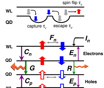
The cavity of the QD spin-laser is in resonance with interband transitions between QD-confined levels.Basu et al. (2008) Since the levels are derived from valence and conduction bands, a general description requires keeping track of both electron and hole populations, as previously shown both for bipolar spintronic devices,Žutić et al. (2003); *Zutic2006:PRL; *Zutic2007:JPCM and for QD spin-unpolarized lasers.Fiore and Markus (2007) The QDs capture electrons and holes from energy levels of a two-dimensional QW-like wetting layer (WL), which acts as a reservoir of carriers. Dery and Eisenstein (2005), [TreatmentoftheWLasasinglelevelisjustifiedbytherelativelyfastenergy-relaxationprocessestothelowestlevel(respectivelyforelectronsandholes)inthewettinglayer; see]Dery2004:IJoQE Figure 1 depicts the level structure and the various processes represented by our REs, from carrier injection to photon emission.
We describe the carriers by eight spin-resolved REs, coupled to two REs for two circular polarizations of stimulated emission:
| (3) | |||||
| (4) | |||||
| (5) |
cf. Fig. 1. The index stands for WL and for QDs, while for electrons and holes, respectively. Equations (3) and (4) describe carrier occupancies, , in WL and QDs, related to the corresponding numbers of particles and :
| (6) | |||||
| (7) |
Here is the number of states in WL and is the number of QDs. The ratio , used in Eqs. (3) and (4), is an important parameter of the QD laser.Summers and Rees (2007) For simplicity, we assume that each QD hosts one double-degenerate level per species . This can be realized only for electron levels in small enough QDs, Grundmann et al. (1996) but we do not expect our results to be qualitatively changed upon inclusion of QD excited states. As long as the lasing transitions involve only QD-confined levels, the limited density of QD states and the limited capture rate will affect the spin-laser characteristics in the way discussed below. The ground state of holes is assumed to be formed predominantly from heavy-hole wavefunctions. The electron (hole) level is degenerate with respect to spin (angular momentum ) projection.Žutić et al. (2004)
Equations (5) is for photon occupancies, , of helicities , defined as
| (8) |
where is the number of cavity photons of the given helicity. Our sign convention for indices denoting the spin projections and helicities follows Ref. Gøthgen et al., 2008. In Eq. (5), is the optical confinement factor and is the photon cavity lifetime. The terms
| (9) | |||||
| (10) | |||||
| (11) |
represent carrier injection, carrier capture from the WL to QDs, and the inverse process of escape, respectively. is the number of carriers of species injected into the laser per WL state of the given spin and unit time, with . The injection spin polarization is . The parameters and are the capture and escape times.
To correctly describe consequences of the small density of QD states, as well as saturation of the WL states at high injection, it is important to include in Eqs. (9)–(11) the Pauli-blocking factors, , of the WL and QD states.Summers and Rees (2007) These terms, omitted in some previous work on QD-based spin-lasers, Basu et al. (2009) impede carrier transfer to states close to saturation. We find that they are particularly important in description of the limited QD occupancies, as shown below.
Defining , we write the spontaneous radiative recombination in Eqs. (3) and (4) as
| (12) |
where gives the recombination rate. The spin-relaxation terms
| (13) |
equilibrate spin subpopulations with relaxation times . A realistic model of a steady-state or dynamic operation of spin-lasers, should reflect the different behaviors of electron and hole spins. Gøthgen et al. (2008); Lee et al. (2010) Due to the strong spin-orbit coupling in the valence band, the spin polarization of holes is lost relatively quickly, i.e., , both in QWs (i.e., also in the WL) and QDs.Žutić et al. (2004); Rudolph et al. (2003); Hall et al. (2007) Therefore we assume that the holes, unlike electrons, are spin-unpolarized, i.e., and , which implies in Eq. (9). Additionally, the electron spin-relaxation in QWs is faster than in QDs, thus we take This a very good approximation at low temperatures,Paillard et al. (2001) and it remains reasonable at room temperature, where reaches 1 ns.Robb et al. (2007)
The gain term in Eqs. (4) and (5)
| (14) |
describes coupling of the carriers and light, which gives rise to stimulated emission. The sign ordering in subscripts is consistent with the optical selection rules for interband transitions.Žutić et al. (2004) The constant is independent of photon occupancies , i.e., it does not contain the gain compression terms.Carroll et al. (1998); Chuang (2009) In spite of that, our QD model naturally predicts light-output saturation due to the limited capture capacity of QDs, as discussed below. We note that, owing to the above-mentioned spin asymmetry between electrons and holes, the assumption is not justified for . Thus, an attempt to express, e.g., [Eq. (14)] using only (and ), would lead to incorrect threshold values, even for the QW spin-laser model.
III Results
We focus on the steady-state regime, in which the total charge in the spin-laser is constant. This imposes a relation between and . One of the REs for carriers then becomes linearly dependent on the others, and we replace it with the condition of overall charge neutrality. In the spirit of the simple RE approach, we neglect carrier-carrier Coulomb interactions, which may become important at high injection.Schneider et al. (2001)
We have obtained all formulas presented below by solving the REs analytically. To give simple expressions that offer insight into the behavior of the spin-laser, we assume , , and [Consequencesof$τ_cn/τ_en≠τ_cp/τ_ep$forspin-unpolarizedQDlasershavebeendiscussedin]Viktorov2005:APL We have checked that the spontaneous-emission coupling to the lasing mode has a negligible effect on our results.Gøthgen et al. (2008); Lee et al. (2010) Thus we set the coupling factor . This allows for an unambiguous determination of the laser thresholds.
To develop a preliminary understanding of the QD model of a spin-laser, we relate it to the simpler QW model, discussed in Sec. I. In the limit of and , vanish, as can be inferred from Fig. 1. In this case, WL plays no role in the above QD model, which becomes ”QW-like”, i.e., similar (but not identical) to the QW model of Sec. I. We emphasize that it is not our goal here to compare the absolute thresholds of a QW- and a QD-based laser. Such a comparison requires distinct parameters for these two structures, and shows the potential for achieving lower thresholds in the latter. Asryan and Suris (2002); Bimberg et al. (1999); Blood (2009) Here, we use the same range of parameters for the QD model and for its QW-like limit (except for ). Thus, the QW-like model leads to lower thresholds, since it describes effectively a QD-based structure in the limit of instant capture. Nevertheless, this approach enables us to elucidate important qualitative differences between the QW- and QD-based spin-lasers.
First, we consider consequences of the finite capture rate, , for a spin-unpolarized laser, , illustrated in the inset of Fig. 2.
Let be the threshold for a given . For any , the QD occupancies are independent of and fulfill , where is the occupancy pinned at the threshold value,Summers and Rees (2007)
| (15) |
We normalize the light-injection characteristics using quantities in the limit of instant capture, . The total photon occupancy, , is expressed in terms of
| (16) |
while the injection is normalized to
| (17) |
Unlike the pinned occupancies, increases with (Fig. 2, inset) as
| (18) |
where is the maximum capture rate , Eq. (10), realized for . The factor in Eq. (18) imposes an upper limit on above which lasing is impossible . The limiting condition, means that must overcome the recombination losses, , determining . When , the threshold reduces to from Eq. (17).
In a model of a QW laser with no gain compression, the laser light intensity depends linearly on injection (we neglect the small deviations from linearity that appear around the thresholds when the coupling factor ). A linear dependence is also found for the QD model with . In contrast, the QD model with reveals a sub-linear dependence (Fig. 2, inset), even though we do not introduce any gain-compression terms. [][reportsfindingsfor$P_Jn=0$withadditionallevelsandintroducingadditionalgaincompressionfactor$ϵ$; definedinRef.45.]Sugawara1997:APL At higher injection the emission saturates, as discussed below for the spin-polarized injection scenario.
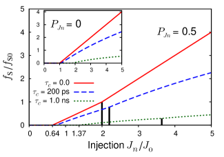
Next, we turn to the spin-polarized injection, i.e., . Similarly to the QW model from Sec. I, our QD model predicts two lasing thresholds, 111This is true for parameters that give a finite [see Eq. (18)], and except such special cases as , , in which is never reached, (i.e., one of is zero for any ). , as shown in Fig. 2, main panel. We find that, in general, the increase of and with is quantitatively similar to the increase of . A particularly simple example is the minority threshold in the limit of :
| (19) |
valid for any , , and identical to the relation found for the QW-based laser.
Such simple, universal relations are typical for the QW model, but not for the QD one with . Even with the simplifying assumptions: , , large (i.e., ), and , we obtain a more complicated ratio for the majority threshold
| (20) | |||||
showing that the threshold reduction , Eq. (1), depends on . Equation (20) reduces to the simple QW-model result for (Eq. 4 of Ref. Gøthgen et al., 2008 in the limit w, i.e., infinite spin relaxation time) .
Figure 3 shows the evolution of and as a function of the capture time. We use a range of , which reflects the scope of values found in previous works.Fiore and Markus (2007); De Giorgi et al. (2001) We start from an initial set of parameters: ps, Rudolph et al. (2005) , [Typical$b_qτ_\mathrm{ph}$valuesare$∼10^-3$; ][.Weusealargervalue($10^-2$); toeffectivelytakeintoaccounttherecombinationintheWL; sinceweset$R_w=0$fortransparencyofourapproach.LossesoutsideQDsmaybeimportantforlasermodeling(Ref.50).]Cao2004:APL ,Melnik et al. (2006) ,Matthews et al. (2002) , , and then we vary some of the values to determine the relevant trends. The limit enables us to obtain analytical formulas [such as Eq. (20)], we also present numerical results for 100 and 200 ps, i.e., the order of magnitude found in experiments. Jarasiunas et al. (2004); *Schreiber2007:PSSB

Both and increase with since the capture rate into the QDs, Eq. (10), decreases. Comparing to (solid and dashed line, lower panel), we note only a small decrease in the threshold reduction defined in Eq. (1); , versus . Using these values, we calculate the ”spin-filtering” interval, Eq. (2), from Eqs. (1) and (19) for . It decreases monotonically from the maximum for to for ps, only a small shrinking of the ”filtering” region.
In the limit of , we find that , , and rise uniformly with decreasing capture rate for a wide range of parameters, e.g., see the solid, dashed and crosses line in Fig. 3. For decreasing , however, both and approach (dotted and dash-dotted line), so the values of and decrease. If the time that the electrons spend in the WL is not much shorter than , their spin polarization will be largely erased before capture by the QDs. The typical times, 1 to 10 ps, make this scenario unlikely.
The influence of escape time on the thresholds is modest. Keeping the ratio fixed, and increasing we find similar shifts of and to slightly higher values. By changing from zero to 1.25 (zero to high-temperature limitSummers and Rees (2007)), the spin-filtering region decreases from to , with similar changes in the interval (the other parameters retaining the initial values).
It is interesting to consider the influence of the optical matrix element of the lasing transition, . Increasing results in a proportional increase of both and ,Chuang (2009) representing gain and radiative losses, respectively. The increase of the losses prevails, so that all the thresholds rise. The value of is an example: in Eq. (17) decreases with increasing (increasing ) to the minimum 1/2, but grows indefinitely. Figure 3 shows the corresponding change of and on the example of a three-fold increase of . The matrix element modifies to a different extent than . With growing , the threshold rises faster, which results in a higher and . For example, setting ps and using the initial parameters, except for ps (appropriate for room temperature Jarasiunas et al. (2004); *Schreiber2007:PSSB), we find , . These values increase to , for and (a four-fold increase of ). We find a similar improvement of with increasing photon lifetime . The above value of rises to 0.22, when changes from 1 to 4 ps. Thus, the detrimental effect of spin relaxation in WL can be mitigated by modifying laser parameters not related to spin.
Apart from increasing the thresholds, the limited supply of carriers to the lasing transition causes output saturation. This can be understood by looking at the regime of high injection. High drives the WL occupancies close to saturation, , because the finite limits carrier relaxation to QDs. In this regime, the capture rates approach their maxima, [see Eq. (18)], so that the injection into QDs no longer grows with . The asymptotic value of photon occupancy
| (21) |
is independent of .Not We obtain for . Interestingly, , so that the circular polarization of laser light, , is zero for high injection, in contrast to the QW model, where .Gøthgen et al. (2008) This can be explained as follows. In a QW-laser model with no gain compression term, levels participating in the laser action are assumed to be replenished instantaneously (a characteristic relaxation time is , Ref. Carroll et al., 1998). The capture process to the discrete, widely spaced QD levels is slower,Schneider et al. (2001) and must be treated explicitly in a realistic QD model. As noted above, this leads to at sufficiently high , so the electrons captured into the QDs are spin-unpolarized and consequently .
Finally, we note that the limited capture rate is not the only difference between QW- and QD-based lasers. Since , Eq. (15) imposes a lower limit on the gain required for lasing: for any and the other parameters. The QW model of Sec. I predicts no such limit. A more restrictive condition must be satisfied to maintain the full threshold reduction: in the limit. Decreasing below results in a decrease of , which vanishes completely, when . These effects are a direct consequence of the limited density of states at the lasing transition, a limitation that can be neglected in QW-based lasers operating at low powers. We also note that the upper bound must be enforced by including Pauli-blocking terms, otherwise the REs lead to incorrect results, also for . For example, if the term in Eq. (10) is omitted ( is any of the equal QD occupancies), the REs allow for the unphysical , so that is always reached, even when . For and ps, the omission of leads to relative errors of as high as 30%.
IV Conclusions
In this work we have developed a transparent rate-equation approach, which has allowed for analytical results. Using this formalism, we have elucidated various trends in operation of QD spin-lasers, comparing them to their relatively well-known QW-based counterparts. In particular, we have studied the consequences of finite capture rate by QD-confined levels, which participate in the lasing transition. To fully preserve the threshold reduction and the ”spin-filtering” effects resulting from spin injection, the capture time has to be much shorter than the spin relaxation time in the wetting layer. Nevertheless, we have found that, when the spin relaxation lowers the electron spin polarization appreciably, the threshold reduction and the ”spin-filtering” window can be partially restored by modifying some spin-independent laser parameters. Another consequence of the finite capture rate is saturation of stimulated emission as a function of injection. Furthermore, QD- and QW-based lasers have qualitatively different densities of the initial and final states of lasing transitions. The threshold reduction in QD lasers may be hindered by the small density of QD states, if the the gain or the photon cavity lifetime are too small.
To take full advantage of the potential of electrical spin injection in QD spin-lasers, it is important to further improve their magnetic contacts (injectors). The current maximum temperature of 200 K for electrically injected spin-lasers using MnAs injector,Basu et al. (2008) will likely be soon improved, since the same spin injector material was recently demonstrated to operate at room temperature.Fraser et al. (2010) Fe Schottky contacts have also been used to inject spins in (In,Ga)As QDs at room temperature.Li et al. (2005) For the surface-emitting spin lasers, magnetic injectors with out-of-plane remanent magnetization would be desirable. Hövel et al. (2008) In such a geometry, the spin-laser operation is possible without the need to apply an external magnetic field, since the optical selection rules lead to circularly polarized light.Žutić et al. (2004) Encouraging results have been reported recently for spin light-emitting diodes utilizing MgO tunnel contacts,Hövel et al. (2008) which provide a very efficient room-temperature spin injection.Jiang et al. (2005)
V Acknowledgements
This work was supported by the U.S. ONR, AFOSR-DCT, NSF-ECCS CAREER, and DOE-BES.
References
- Žutić et al. (2004) I. Žutić, J. Fabian, and S. Das Sarma, Rev. Mod. Phys., 76, 323 (2004).
- Rudolph et al. (2005) J. Rudolph, S. Döhrmann, D. Hägele, M. Oestreich, and W. Stolz, Appl. Phys. Lett., 87, 241117 (2005).
- Holub et al. (2007) M. Holub, J. Shin, D. Saha, and P. Bhattacharya, Phys. Rev. Lett., 98, 146603 (2007).
- Hövel et al. (2008) S. Hövel, A. Bischoff, N. C. Gerhardt, M. R. Hofmann, T. Ackemann, A. Kroner, and R. Michalzik, Appl. Phys. Lett., 92, 041118 (2008a).
- Meier and Zakharchenya (1984) F. Meier and B. P. Zakharchenya, eds., Optical Orientation (North-Holland, New York, 1984).
- Fabian and Žutić (2008) J. Fabian and I. Žutić, Semicond. Sci. Technol., 23, 114005 (2008).
- Lü et al. (2009) H.-F. Lü, Y. Guo, X.-T. Zu, and H.-W. Zhang, Appl. Phys. Lett., 94, 162109 (2009).
- Ando et al. (1998) H. Ando, T. Sogawa, and H. Gotoh, Appl. Phys. Lett., 73, 566 (1998).
- Hallstein et al. (1997) S. Hallstein, J. D. Berger, M. Hilpert, H. C. Schneider, W. W. Rühle, F. Jahnke, S. W. Koch, H. M. Gibbs, G. Khitrova, and M. Oestreich, Phys. Rev. B, 56, R7076 (1997).
- Rudolph et al. (2003) J. Rudolph, D. Hägele, H. M. Gibbs, G. Khitrova, and M. Oestreich, Appl. Phys. Lett., 82, 4516 (2003).
- Fujino et al. (2009) H. Fujino, S. Koh, S. Iba, T. Fujimoto, and H. Kawaguchi, Appl. Phys. Lett., 94, 131108 (2009).
- Gerhardt et al. (2010) N. C. Gerhardt, M. Li, H. Jaehme, H. Soldat, M. R. Hofmann, and T. Ackemann, Physics and Simulation of Optoelectronic Devices XVIII, 7597, 75970Q (2010).
- Basu et al. (2008) D. Basu, D. Saha, C. C. Wu, M. Holub, Z. Mi, and P. Bhattacharya, Appl. Phys. Lett., 92, 091119 (2008).
- Alferov (2001) Z. I. Alferov, Rev. Mod. Phys., 73, 767 (2001).
- Arakawa and Sakaki (1982) Y. Arakawa and H. Sakaki, Appl. Phys. Lett., 40, 939 (1982).
- Abolfath et al. (2008) R. M. Abolfath, A. G. Petukhov, and I. Žutić, Phys. Rev. Lett., 101, 207202 (2008).
- Maximov et al. (2000) M. V. Maximov, A. F. Tsatsul’nikov, B. V. Volovik, D. S. Sizov, Y. M. Shernyakov, I. N. Kaiander, A. E. Zhukov, A. R. Kovsh, S. S. Mikhrin, V. M. Ustinov, Z. I. Alferov, R. Heitz, V. A. Shchukin, N. N. Ledentsov, D. Bimberg, Y. G. Musikhin, and W. Neumann, Phys. Rev. B, 62, 16671 (2000).
- Asryan and Suris (2002) L. V. Asryan and R. A. Suris, Quantum Dots, edited by E. Borovitskaya and M. E. Shur, Selected Topics in Electronics and Systems, Vol. 25 (World Scientific, 2002) p. 111.
- Sellers et al. (2004) I. Sellers, H. Liu, K. Groom, D. Childs, D. Robbins, T. Badcock, M. Hopkinson, D. Mowbray, and M. Skolnick, Electron. Lett., 40, 1412 (2004).
- Fabian et al. (2007) J. Fabian, A. Matos-Abiague, C. Ertler, P. Stano, and I. Žutić, Acta Phys. Slov., 57, 565 (2007).
- San Miguel et al. (1995) M. San Miguel, Q. Feng, and J. V. Moloney, Phys. Rev. A, 52, 1728 (1995).
- Dyson and Adams (2003) A. Dyson and M. J. Adams, J. Opt. B: Quantum Semiclassical Opt., 5, 222 (2003).
- Vurgaftman et al. (2008) I. Vurgaftman, M. Holub, B. T. Jonker, and J. R. Meyer, Appl. Phys. Lett., 93, 031102 (2008).
- Basu et al. (2009) D. Basu, D. Saha, and P. Bhattacharya, Phys. Rev. Lett., 102, 093904 (2009).
- Gøthgen et al. (2008) C. Gøthgen, R. Oszwałdowski, A. Petrou, and I. Žutić, Appl. Phys. Lett., 93, 042513 (2008).
- Lee et al. (2010) J. Lee, W. Falls, R. Oszwałdowski, and I. Žutić, Appl. Phys. Lett., 97, 041116 (2010).
- Yakovlev and Bayer (2008) D. R. Yakovlev and M. Bayer, “Spin physics in semiconductors,” (Springer, Berlin, 2008) pp. 135–177.
- Oestreich et al. (2005) M. Oestreich, J. Rudolph, R. Winkler, and D. Hägele, Superlatt. Microstruct., 37, 306 (2005).
- Klochikhin et al. (2008) A. Klochikhin, A. Reznitsky, S. Permogorov, E. Tsitsishvili, R. v Baltz, H. Kalt, and C. Klingshirn, Semiconductor Science and Technology, 23, 114010 (2008).
- Stano and Fabian (2006) P. Stano and J. Fabian, Phys. Rev. B, 74, 045320 (2006).
- Passow et al. (2002) T. Passow, M. Klude, C. Kruse, K. Leonardi, R. Kröger, G. Alexe, K. Sebald, S. Ulrich, P. Michler, J. Gutowski, H. Heinke, and D. Hommel, Advances in Solid State Physics, 42, 13 (2002).
- Sellers et al. (2009) I. R. Sellers, R. Oszwałdowski, V. R. Whiteside, M. Eginligil, A. Petrou, I. Žutić, W.-C. Chou, W. C. Fan, A. G. Petukhov, and B. D. McCombe, “Robust magnetic polarons in type-II (Zn,Mn)Te quantum dots,” arXiv:0912.0138v1 (2009).
- Klimov (2007) V. I. Klimov, Annu. Rev. Phys. Chem., 58, 635 (2007).
- Scholes (2008) G. D. Scholes, Adv. Funct. Mater., 18, 1157 (2008).
- Stern et al. (2005) N. P. Stern, M. Poggio, M. H. Bartl, E. L. Hu, G. D. Stucky, and D. D. Awschalom, Phys. Rev. B, 72, 161303 (2005).
- Klimov et al. (2007) V. I. Klimov, S. A. Ivanov, J. Nanda, M. Achermann, I. Bezel, J. A. McGuire, and A. Piryatinski, Nature, 447, 441 (2007).
- Beaulac et al. (2008) R. Beaulac, P. I. Archer, S. T. Ochsenbein, and D. R. Gamelin, Advanced Functional Materials, 18, 3873 (2008).
- Žutić et al. (2003) I. Žutić, J. Fabian, and S. D. Sarma, Appl. Phys. Lett., 82, 221 (2003).
- Žutić et al. (2006) I. Žutić, J. Fabian, and S. C. Erwin, Phys. Rev. Lett., 97, 026602 (2006).
- Žutić et al. (2007) I. Žutić, J. Fabian, and S. C. Erwin, J. Phys.: Condens. Matter, 19, 165219 (2007).
- Fiore and Markus (2007) A. Fiore and A. Markus, IEEE J. Quantum. Electron., 43, 287 (2007).
- Dery and Eisenstein (2005) H. Dery and G. Eisenstein, IEEE J. Quantum. Electron., 41, 26 (2005).
- Dery and Eisenstein (2004) H. Dery and G. Eisenstein, IEEE J. Quantum Electron., 40, 1398 (2004).
- Summers and Rees (2007) H. D. Summers and P. Rees, J. Appl. Phys., 101, 073106 (2007).
- Grundmann et al. (1996) M. Grundmann, N. N. Ledentsov, O. Stier, J. Böhrer, D. Bimberg, V. M. Ustinov, P. S. Kop’ev, and Z. I. Alferov, Phys. Rev. B, 53, R10509 (1996).
- Hall et al. (2007) K. C. Hall, E. J. Koerperick, T. F. Boggess, O. B. Shchekin, and D. G. Deppe, Appl. Phys. Lett., 90, 053109 (2007).
- Paillard et al. (2001) M. Paillard, X. Marie, P. Renucci, T. Amand, A. Jbeli, and J. M. Gérard, Phys. Rev. Lett., 86, 1634 (2001).
- Robb et al. (2007) J. L. Robb, Y. Chen, A. Timmons, K. C. Hall, O. B. Shchekin, and D. G. Deppe, Appl. Phys. Lett., 90, 153118 (2007).
- Carroll et al. (1998) J. E. Carroll, J. Whiteaway, and R. G. S. Plumb, Distributed Feedback Semiconductor Lasers (The Institution of Engineering and Technology, Edison, NJ, USA, 1998).
- Chuang (2009) S. L. Chuang, Physics of Optoelectronic Devices, 2nd ed. (Wiley, New York, 2009).
- Schneider et al. (2001) H. C. Schneider, W. W. Chow, and S. W. Koch, Phys. Rev. B, 64, 115315 (2001).
- Viktorov et al. (2005) E. A. Viktorov, P. Mandel, Y. Tanguy, J. Houlihan, and G. Huyet, Appl. Phys. Lett., 87, 053113 (2005).
- Bimberg et al. (1999) D. Bimberg, M. Grundmann, and N. N. Ledentsov, Quantum Dot Heterostructures (John Wiley & Sons, 1999).
- Blood (2009) P. Blood, IEEE J. Sel. Top. Quantum Electron., 15, 808 (2009).
- Sugawara et al. (1997) M. Sugawara, K. Mukai, and H. Shoji, Appl. Phys. Lett., 71, 2791 (1997).
- (56) This is true for parameters that give a finite [see Eq. (18)], and except such special cases as , , in which is never reached, (i.e., one of is zero for any ).
- De Giorgi et al. (2001) M. De Giorgi, C. Lingk, G. von Plessen, J. Feldmann, S. D. Rinaldis, A. Passaseo, M. D. Vittorio, R. Cingolani, and M. Lomascolo, Appl. Phys. Lett., 79, 3968 (2001).
- Cao and Deppe (2004) C. Cao and D. G. Deppe, Appl. Phys. Lett., 84, 2736 (2004).
- Melnik et al. (2006) S. Melnik, G. Huyet, and A. Uskov, Opt. Express, 14, 2950 (2006).
- Matthews et al. (2002) D. R. Matthews, H. D. Summers, P. M. Smowton, and M. Hopkinson, Appl. Phys. Lett., 81, 4904 (2002).
- Jarasiunas et al. (2004) K. Jarasiunas, R. Aleksiejunas, V. Gudelis, L. Subacius, M. Sudzius, S. Iwamoto, T. Shimura, K. Kuroda, and Y. Arakawa, Semicond. Sci. Technol., 19, S339 (2004).
- Schreiber et al. (2007) L. Schreiber, D. Duda, B. Beschoten, G. Güntherodt, H.-P. Schönherr, and J. Herfort, Phys. Status Solidi B, 244, 2960 (2007).
- Fraser et al. (2010) E. D. Fraser, S. Hegde, L. Schweidenback, A. H. Russ, A. Petrou, H. Luo, and G. Kioseoglou, Appl. Phys. Lett., 97, 041103 (2010).
- Li et al. (2005) C. H. Li, G. Kioseoglou, O. M. J. van ’t Erve, M. E. Ware, D. Gammon, R. M. Stroud, B. T. Jonker, R. Mallory, M. Yasar, and A. Petrou, Appl. Phys. Lett., 86, 132503 (2005).
- Hövel et al. (2008) S. Hövel, N. C. Gerhardt, M. R. Hofmann, F.-Y. Lo, A. Ludwig, D. Reuter, A. D. Wieck, E. Schuster, H. Wende, W. Keune, O. Petracic, and K. Westerholt, Appl. Phys. Lett., 93, 021117 (2008b).
- Jiang et al. (2005) X. Jiang, R. Wang, R. M. Shelby, R. M. Macfarlane, S. R. Bank, J. S. Harris, and S. S. P. Parkin, Phys. Rev. Lett., 94, 056601 (2005).