Magnetic Vortex Core Reversal by Excitation of Spin Waves
Abstract
Micron-sized magnetic platelets in the flux closed vortex state are characterized by an in-plane curling magnetization and a nanometer-sized perpendicularly magnetized vortex core. Having the simplest non-trivial configuration, these objects are of general interest to micromagnetics and may offer new routes for spintronics applications. Essential progress in the understanding of nonlinear vortex dynamics was achieved when low-field core toggling by excitation of the gyrotropic eigenmode at sub-GHz frequencies was established. At frequencies more than an order of magnitude higher vortex state structures possess spin wave eigenmodes arising from the magneto-static interaction. Here we demonstrate experimentally that the unidirectional vortex core reversal process also occurs when such azimuthal modes are excited. These results are confirmed by micromagnetic simulations which clearly show the selection rules for this novel reversal mechanism. Our analysis reveals that for spin wave excitation the concept of a critical velocity as the switching condition has to be modified.
Thin film soft magnetic platelets of suited micron or submicron size are characterized by an in-plane closed flux magnetization, minimizing the dipolar energy. However, at the centre, the exchange energy forces the magnetization out-of-plane in a small area of only a few exchange lengths in diameter Shinjo2000 ; Wachowiak2002 creating the vortex core with a distinct polarization , either up () or down (). The vortex introduces an important sub-GHz mode to the excitation spectrum of the magnetization Huber1982 , which corresponds to the gyrotropic motion of the vortex.
Recently, dynamic vortex core reversal was discovered by application of pulsed magnetic fields Xiao2006 ; Hertel2007 ; Weigand2009 , alternating magnetic fields VanWaeyenberge2006 ; Curcic2008 ; Lee2008 ; deLoubens2009 or spin polarized currents Yamada2007 ; Yamada2008 . These discoveries did not only open up the possibility of using magnetic vortices as memory bits and further spintronics applications Kim2008 ; Bohlens2008 ; Pigeau2010 , but also initiated wide investigation of the physics behind this reversal mechanism.
The reversal process appeared to be universal and independent of the type of excitation: it proceeds through the creation and subsequent annihilation of a vortex-antivortex pair VanWaeyenberge2006 ; Hertel2007 ; Guslienko2008100 . The source of this pair is the dynamical distortion of the otherwise stable vortex: it forms a ’dip’ – an oppositely polarized region close to the moving vortex core Volkel1994 ; Vansteenkiste2009 . Guslienko et al. Guslienko2008100 explained this ’dip’-formation by an effective field, the gyrofield, which is proportional to the vortex core velocity. This leads to the concept of a critical velocity for switching, which is about 320 m/s in Permalloy Guslienko2008100 .
Furthermore, the sense of rotation of a freely gyrating vortex is determined by the vortex core polarization Thiele1973 ; Huber1982 ; Choe2004 , a property which manifests itself in a high asymmetry of the gyrotropic resonance excited by rotating magnetic fields with different rotation senses Lee2008 . This can be utilized to selectively reverse the core polarization, as shown experimentally by Curcic et al. Curcic2008 . Micromagnetic simulations from Kravchuk et al. Kravchuk2007 ; Kravchuk2009 have indicated that rotating magnetic fields can even induce vortex core reversal at GHz frequencies as a result of the vortex spin wave interaction.
Here we present experiments which verify that polarisation selective vortex core reversal can indeed be achieved by spin wave excitation with in-plane rotating GHz magnetic fields. However, compared to the results of Kravchuk et al. Kravchuk2007 where only one spin wave mode was consiered, we will present selection rules for different modes. And in contrast to the calculations given by Kravchuk et al. Kravchuk2009 where the vortex core was artificially fixed during spin wave excitation, we will demonstrate by micromagnetic simulations that the core motion is essential and explains the differences observed in the vortex core switching triggered by distinct spin waves.
Results
The presence of the vortex core does not only introduce the gyrotropic mode, but also modifies the high-frequency spin wave normal mode spectrum Park2003 ; Buess2005 ; Buess2004 ; neudecker2006 by lifting the degeneracy of the azimuthal modes with opposite rotation sense Zaspel2005 ; Park2005 ; Zhu2005 ; Hoffmann2007 ; Guslienko2008101 ; Guslienko2010 . The out-of-plane component of the magnetization of these azimuthal spin waves can be described in polar coordinates as Buess2005 :
| (1) |
These modes are characterised by a radial mode number (positive integer values starting with 1) denoting the number of nodes of the radial part within the disk and an azimuthal mode number (integer values), with being the number of nodes in the azimuthal part. The sign of denotes the rotation sense of the azimuthal wave (CCW: positive , CW: negative). The symmetry in the frequency splitting of the azimuthal mode can be written as .
A general concept of resonant vortex core reversal by rotating magnetic fields is sketched in Fig. 1. On the left-hand side, the gyrotropic mode (, ), is shown with a CCW sense of rotation for a core up state, and a CW sense of rotation for a core down state. The vortex core can only be reversed resonantly by applying an external rotating magnetic field if its frequency and sense of rotation correspond to the mode, as already shown experimentally in Curcic2008 . On the right hand side of Fig. 1, the frequency-split azimuthal modes are shown. For a vortex up this means that the mode with a CW sense of rotation, denoted by (, ), has a lower frequency and the mode with a CCW sense of rotation, denoted by (, ), has a higher frequency. For a vortex core down the sign of the azimuthal mode number , indicating the sense of rotation, is reversed for the higher and lower frequency modes compared to vortex core up, as sketched at the bottom part of Fig. 1. These spin wave modes with (, ) can be selectively excited by the application of rotating in-plane magnetic fields with the corresponding frequency and rotation sense. Thus at a fixed GHz frequency and core polarity the excitation is polarization selective in the same way as for the sub-GHz gyrotropic mode: only rotating fields with one rotation sense will pump the system. This suggests that a similar polarization selective switching mechanism for the vortex core may exist when any of the azimuthal spinwave modes are excited, albeit at much higher frequencies.
Experimental Results
We excited ferromagnetic Permalloy discs, 1.6 m in diameter, 50 nm thick, in the vortex magnetic ground state with bursts of GHz rotating magnetic fields of variable frequency and amplitude. The fields were applied with either a clockwise (CW) or counterclockwise (CCW) rotation sense Curcic2008 . Magnetic scanning soft X-ray microscopy at the MAXYMUS endstation, Helmholtz Zentrum Berlin, BESSY II was used to determine the out-of-plane magnetization of the vortex core.
The experimental verification of the concept as described before is presented in Fig. 2 (upper part). It shows the vortex core switching events from the initial vortex core up state to the down state as a function of excitation frequency, amplitude and sense of rotation of the external field. Here, the burst length was fixed at 24 periods of the excitation frequency. Three regions with a minimum in amplitude for vortex core reversal can be observed in the experimental data. Dependent on the sense of rotation of the external magnetic field they are marked with blue or red backgrounds. The regions for CW excitation at about 4.5 GHz and 6.5 GHz, CCW excitation at about 5.5 GHz can be assigned to the (, ), (, ) and (, ) spin wave modes, respectively (cf. Fig. 1 and the middle part of Fig. 2).
Micromagnetic Simulations
In order to further investigate the core reversal at these different modes, we performed micromagnetic simulations OOMMF for the same sample size and experimental conditions. The results are shown in Fig. 2, lower part and are in good agreement with our experimental results. The small differences between the experimental and simulated results can be attributed to the uncertainty in the thickness, saturation magnetization and damping coefficient of the material, as well as to possible structural imperfections in the samples. The phases of a local Fourier analysis Park2003 ; Buess2004 of the dynamic magnetization let us clearly identify the azimuthal modes (cf. Fig. 2, lower right part). The simulations with an extended frequency range up to 10.5 GHz reveal even more spin wave eigenmodes capable of vortex core reversal: the (, ) mode at about 9 GHz and the two () spin wave modes at about 10 and 10.3 GHz.
Both the experiments and the micromagnetic simulations show that resonant switching of the vortex core from the down state back to the up state at the same frequency can be achieved only if the sense of rotation of the external field is reversed. This allows selective and unidirectional switching at each resonance frequency.
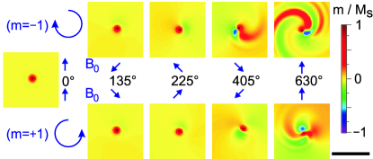
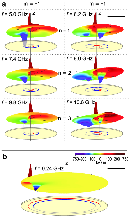
Detailed analysis of the micromagnetic simulations reveal that the excitation of all spinwave modes also leads to the creation of a ’dip’ near the vortex core, resulting in the same core reversal mechanism as found for gyrotropic excitation VanWaeyenberge2006 ; Hertel2007 ; Vansteenkiste2009 . It is based on the creation and annihilation of a vortex-antivortex pair. But the ’dip’ creation itself differs dependent on which spin wave mode is excited. This ’dip’ creation for a vortex up () is illustrated by snapshots of the simulations in Fig. 3 for the modes (, ). In the first frame (0°), the unperturbed out-of-plane magnetization of the vortex can be seen. After a short time of excitation (135° phase angle) the azimuthal spin wave with the same rotation sense as the external field develops. The interaction of the spin waves with the gyrotropic mode leads to a displacement of the vortex core towards the oppositely polarized region of the bipolar mode, resulting in a gyration with the same frequency as the external field (225° phase angle). At 405°, a negatively polarized out-of-plane region can be observed next to the core, to the outside with respect to the centre. It is gyrating around the centre almost in phase with the vortex core. In the () case (upper panels), this region develops into a ’dip’ which finally leads to core reversal. But surprisingly, for the () in the lower panels, there is an additional negatively polarized region. This region is situated towards the structure centre where the azimuthal mode has a positive polarization and gyrates with a phase shift of about 180° with respect to the vortex core. As can be seen from the last frame at 630°, it is this region which evolves into a fully out-of-plane ’dip’, creating the vortex-antivortex pair for switching. The typical magnetization configurations are shown in Fig. 4 including the higher radial mode numbers. The trajectories for the vortex core as well as for the ’dips’ and their relative phases are illustrated by arrows.
Discussion
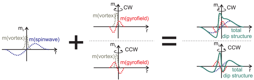
The gyrofield, as used by Guslienko et al. to describe the ’dip’ formation in the gyrotropic mode Thiele1973 ; Guslienko2008100 , can also be taken to explain the difference in ’dip’ formation for the () and () modes, as is sketched in Fig. 5. This effective field originates from the movement of the vortex and results in out-of-plane contributions to the left and right side of the core (in respect to the direction of motion) which are respectively negative and positive (middle sketch in Fig. 5). This velocity dependent behaviour breaks the symmetry between counter rotating vortices. If we now combine the spin wave amplitude with the effect of the gyrofield, we can understand the ’dip’ formation for any of the counter rotating modes (right sketch in Fig. 5). For a vortex up and the mode () with a CW vortex motion, the gyrofield acts constructively on the spin wave amplitude. For the () mode, it acts destructively, causing the double ’dip’ configuration as seen in Fig. 4. Alternatively, these ’dip’ structures can be regarded as a hybridisation between the gyrotropic mode and the azimuthal modes Guslienko2010 . Kravchuk et al. Kravchuk2009 also presented a ’dip’ formation mechanism for spin wave excitation under the condition of an artificially fixed vortex core. However, our results show that this condition can not be used to predict the reversal in free vortices, as in realistic structures. According to their analysis, the polarization direction of the ’dip’ is given by the rotation sense of the external field only. This would mean that reversal of a given core polarization is only possible for one of the two azimuthal modes. E.g. the reversal at the () as presented in Fig. 2 can not be explained with this assumption, as the ’dip’ polarization would be the same as the core polarization. The dynamic origin of the ’dip’ structure clearly explains this contradiction. For a free vortex, the ’dip’ formation seems to be dominated by the gyrofield.
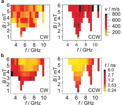
Vortex core reversal by the low-frequency gyromode excitation results in a typical gyration radius of about 300 nm for this kind of sample. In contrast, the gyration radius of the vortex core at GHz frequencies is only in the order of 10 nm (cf. Fig. 4). But due to the high-frequency rotation, this small radius still results in a very high velocity of the vortex core. The top part of Fig. 6 shows the velocities of the vortex core directly before the reversal process as calculated from the simulations. It varies between about 100 m/s () and up to more than 600 m/s (). This demonstrates that for GHz spin wave excitation, no well-defined critical velocity is observed as it was calculated to be about 320 m/s for the gyromode of a Permalloy nanodot Guslienko2008100 .
The reason can be found in our explanation of the ’dip’ formation as a combination of the gyrofield with the spin wave amplitude. Although in first order, the gyrofield is proportional to the vortex velocity, the spin wave amplitude is not and thus the critical velocity before switching is higher or lower than the expected value, depending if their combination is constructive or destructive. Similar arguments were used to explain the changes in critical velocity when perpendicular bias fields are applied Yoo2010 . The large fluctuations in the velocities can be understood when the random contribution of short wavelength spin waves are also taken into account. Consequently, the velocity itself is not a switching criterion for the spin wave mode induced vortex core reversal.
The bottom part of Fig. 6 shows how long it takes for the vortex to switch after the burst is applied. It is no surprise that the larger the amplitude, the shorter the time for vortex core reversal. The minima in the excitation amplitude show a clear resonant behaviour. At high amplitudes the switching times become smaller than one period of the excitation and the frequency dependence is washed out, indicating the transition to non-resonant excitation Hertel2007 . However, the feature of unidirectionality gets lost in the intersection of two oppositely rotating modes if too short bursts are applied.
Because both the vortex and the created vortex-antivortex pair remain close to the centre of the structure during the excitation, the relaxation after the spin wave induced reversal process is much faster than in the gyrotropic case, where it has to spiral back from its orbit far away to the centre. In combination with the very small gyration radius, this fast relaxation is accelerating the whole reversal process by up to two orders of magnitude, while the total energy pumped into the system is roughly the same compared to reversal at the gyrotropic mode. This fact makes this new reversal process very beneficial for fast technological applications.
In conclusion, our experiments show vortex core reversal at GHz frequencies. By taking advantage of the vortex polarity dependent frequency splitting of the azimuthal modes (, ) we present a concept for unidirectional reversal by exciting any of these modes up to 10 GHz. Although the dynamics depend significantly on the different combinations of core polarity and azimuthal mode number, they can be explained by the superposition of the gyrofield with the spin wave amplitude. Consequently, immediately before the switching event, different vortex core velocities are observed, which excludes the velocity as a critical condition for core reversal at GHz excitation. This finding highlights the importance of spin wave – vortex interaction and boosts vortex core reversal to much higher frequencies, which may offer new routes for spintronics applications.
Methods
Experiments
Permalloy discs, 1.6 m in diameter and 50 nm thickness, are grown on top of 2.5 m wide and 170 nm thick copper striplines patterned on a 100 nm thick silicon nitride membrane. All structures are prepared by electron-beam lithography, thermal evaporation and lift-off processes. AC currents with a phase shift of 90 degree flowing through orthogonal striplines are generating rotating in-plane magnetic fields Curcic2008 . The out-of-plane magnetization of the Permalloy disc was imaged by scanning transmission X-ray microscopy at the MAXYMUS end station at HZB BESSY II, Berlin, by taking advantage of the X-Ray Magnetic Circular Dichroism (XMCD) SCHUTZ1987 . The instrument has a resolution of about 25 nm, which is sufficient to resolve the vortex core and its polarization.
Simulations
Micromagnetic simulations were performed with the Object Oriented Micromagnetic Framework (OOMMF) OOMMF . A disc, 1.62 in diameter and 50 nm thick, was simulated with a cell size of 3 nm 3 nm 50 nm. Typical material parameters for Permalloy Weigand2009 ; Curcic2008 were used: =750 103 A/m, exchange constant =13 10-12 J/m, damping parameter =0.006, anisotropy constant . For all simulations shown, the initial state was a vortex core up. The symmetry of the results were verified by also simulating with the opposite initial state which is a vortex down. The sample was excited by homogeneous in-plane rotating magnetic field bursts with duration of 24 periods. The frequency of the bursts was scanned from 3 GHz to 11 GHz in 0.4 GHz steps for both, CW and CCW sense of rotation.
References
- (1) Shinjo, T., Okuno, T., Hassdorf, R., Shigeto, K. & Ono, T. Magnetic vortex core observation in circular dots of permalloy. Science 289, 930–932 (2000).
- (2) Wachowiak, A. et al. Direct observation of internal spin structure of magnetic vortex cores. Science 298, 577–580 (2002).
- (3) Huber, D. Equation of motion of a spin vortex in a two-dimensional planar magnet. Journal of applied physics 53, 1899–1900 (1982).
- (4) Xiao, Q., Rudge, J., Choi, B., Hong, Y. & Donohoe, G. Dynamics of vortex core switching in ferromagnetic nanodisks. Applied physics letters 89 (2006).
- (5) Hertel, R., Gliga, S., Fahnle, M. & Schneider, C. Ultrafast nanomagnetic toggle switching of vortex cores. Physical Review Letters 98, 117201 (2007).
- (6) Weigand, M. et al. Vortex core switching by coherent excitation with single in-plane magnetic field pulses. Physical Review Letters 102, 077201 (2009).
- (7) Van Waeyenberge, B. et al. Magnetic vortex core reversal by excitation with short bursts of an alternating field. Nature 444, 461–464 (2006).
- (8) Curcic, M. et al. Polarization selective magnetic vortex dynamics and core reversal in rotating magnetic fields. Physical Review Letters 101, 197204 (2008).
- (9) Lee, K. & Kim, S. Two circular-rotational eigenmodes and their giant resonance asymmetry in vortex gyrotropic motions in soft magnetic nanodots. Physical Review B, Condensed matter and materials physics 78, 014405 (2008).
- (10) De Loubens, G. et al. Bistability of vortex core dynamics in a single perpendicularly magnetized nanodisk. Physical Review Letters 102, 177602 (2009).
- (11) Yamada, K. et al. Electrical switching of the vortex core in a magnetic disk. Nature Materials 6, 269–273 (2007).
- (12) Yamada, K., Kasai, S., Nakatani, Y., Kobayashi, K. & Ono, T. Switching magnetic vortex core by a single nanosecond current pulse. Applied physics letters 93 (2008).
- (13) Kim, S., Lee, K., Yu, Y. & Choi, Y. Reliable low-power control of ultrafast vortex-core switching with the selectivity in an array of vortex states by in-plane circular-rotational magnetic fields and spin-polarized currents. Applied Physics Letters 92, 022509 (2008).
- (14) Bohlens, S. et al. Current controlled random-access memory based on magnetic vortex handedness. Applied Physics Letters 93, 142508 (2008).
- (15) Pigeau, B. et al. A frequency-controlled magnetic vortex memory. Applied Physics Letters 96, 132506 (2010).
- (16) Guslienko, K., Lee, K. & Kim, S. Dynamic origin of vortex core switching in soft magnetic nanodots. Physical Review Letters 100, 027203 (2008).
- (17) Vansteenkiste, A. et al. X-ray imaging of the dynamic magnetic vortex core deformation. Nature Physics 5, 332–334 (2009).
- (18) Thiele, A. A. Steady-state motion of magnetic domains. Phys. Rev. Lett. 30, 230–233 (1973).
- (19) Choe, S. B. et al. Vortex core-driven magnetization dynamics. Science 304, 420–422 (2004).
- (20) Kravchuk, V., Sheka, D., Gaididei, Y. & Mertens, F. Controlled vortex core switching in a magnetic nanodisk by a rotating field. Journal of Applied Physics 102, 043908 (2007).
- (21) Kravchuk, V., Gaididei, Y. & Sheka, D. Nucleation of a vortex-antivortex pair in the presence of an immobile magnetic vortex. Physical Review B, Condensed matter and materials physics 80, 100405 (2009).
- (22) Park, J., Eames, P., Engebretson, D., Berezovsky, J. & Crowell, P. Imaging of spin dynamics in closure domain and vortex structures. Physical Review B, Condensed matter and materials physics 67, 020403 (2003).
- (23) Buess, M. et al. Excitations with negative dispersion in a spin vortex. Physical Review B, Condensed matter 71, 104415 (2005).
- (24) Buess, M. et al. Fourier transform imaging of spin vortex eigenmodes. Physical Review Letters 93, 077207 (2004).
- (25) Neudecker, I. et al. Modal spectrum of permalloy disks excited by in-plane magnetic fields. Physical Review B 73, 134426 (2006).
- (26) Zaspel, C., Ivanov, B., J & Crowell, P. Excitations in vortex-state permalloy dots. Physical Review B, Condensed matter and materials physics 72, 024427 (2005).
- (27) Park, J. & Crowell, P. Interactions of spin waves with a magnetic vortex. Physical Review Letters 95, 167201 (2005).
- (28) Zhu, X., Liu, Z., Metlushko, V., Grutter, P. & Freeman, M. Broadband spin dynamics of the magnetic vortex state: Effect of the pulsed field direction. Physical Review B, Condensed matter and materials physics 71, 180408 (2005).
- (29) Hoffmann, F. et al. Mode degeneracy due to vortex core removal in magnetic disks. Physical Review B, Condensed matter and materials physics 76 (2007).
- (30) Guslienko, K. Y., Slavin, A. N., Tiberkevich, V. & Kim, S.-K. Dynamic origin of azimuthal modes splitting in vortex-state magnetic dots. Physical Review Letters 101, 247203 (2008).
- (31) Guslienko, K., Aranda, G. & Gonzalez, J. Topological gauge field in nanomagnets: Spin-wave excitations over a slowly moving magnetization background. Physical Review B, Condensed matter and materials physics 81, 014414 (2010).
- (32) Donahue, M. & Porter, D. Oommf user’s guide, version 1.0. Interagency Report NISTIR 6376, National Institute of Standards and Technology, Gaithersburg, MD (1999).
- (33) Völkel, A. R., Wysin, G. M., Mertens, F. G., Bishop, A. R. & Schnitzer, H. J. Collective-variable approach to the dynamics of nonlinear magnetic excitations with application to vortices. Phys. Rev. B 50, 12711–12720 (1994).
- (34) Yoo, M.-W., Lee, K.-S., Jeong, D.-E. & Kim, S.-K. Origin, criterion, and mechanism of vortex-core reversals in soft magnetic nanodisks under perpendicular bias fields. Phys. Rev. B 82, 174437 (2010).
- (35) Schutz, G. et al. Absorption of circularly polarized x-rays in iron. Physical Review Letters 58, 737–740 (1987).
Acknowledgements.
We would like to thank Manfred Fähnle, MPI Stuttgart, Franz Mertens, Bayreuth University, Yuri Gaididei and Volodymyr Kravchuk, Bogolyubov Institute for Theoretical Physics, Kiev, and Denis Sheka, Kiev University, for fruitful discussions. We would also like to thank all people involved in the construction and operation of the MAXYMUS scanning X-ray microscope at HZB BESSY II in Berlin, in particular Brigitte Baretzky, Michael Bechtel, Rolf Follath, Corinne Grévent and Eberhard Goering. Cooperation with Rolf Heidemann, Ulm University, in the stripline design for microwave application is gratefully acknowledged.Author contributions
Project planning: M.K., H.S., B.V.W., G.S.; Sample preparation: G.W., C.H.B.; Experiments: M.K., M.N., M.S., M.W., M.C.; Micromagnetic simulations: M.K.; Analyse data: M.K., M.C., A.V., B.V.W., H.S.; Writing the paper: M.K., M.N., M.S., M.C., M.W., A.V., B.V.W., H.S., G.W., C.H.B., G.S.
Competing financial interests
The authors declare that they have no competing interests as defined by Nature Publishing Group, or other interests that might be perceived to influence the results and/or discussion reported in this paper.