Detection of the Direct Hyperfine Transition of Positronium Atoms using sub-THz High-power Radiation
Abstract
Hyperfine splitting of positronium is an important parameter for particle physics. This paper gives experimental techniques and results of R&D studies of our experiment to observe direct hyperfine transition of ortho-positronium to para-positronium.
1. Introduction
Positronium is an ideal system for the research of the bound state quantum electrodynamics (QED). The energy difference between ortho-positronium (o-Ps, state) and para-positronium (p-Ps, state), hyperfine splitting of positronium (Ps-HFS), is a good measure for QED validation and also good for a search of unknown phenomena. Previous experimental results of the Ps-HFS show 3.9 (15 ppm) discrepancy from the QED calculation. In order to investigate this discrepancy, we are preparing a new experiment to observe the direct transition of ortho-positronium (o-Ps) to para-positronium (p-Ps) Theoretical and experimental context of HFS measurements are summarized in [1].
Direct HFS transition is caused by applying photons whose energy is just at HFS (203 GHz). We can obtain HFS value by measuring HFS transition rate at several frequencies throughout the Breit-Wigner resonance curve (1.5 GHz FWHM) around the 203 GHz peak. The method of the HFS transition detection is described in Section 3.
The most challenging issue for the direct HFS observation is the photon supply. Since Ps-HFS is ‘M1’ transition, which is prohibited at non-relativistic limit, the natural transition rate is only , which results in very small cross section of the photon-induced HFS transition. Therefore, extremely high photon density of is needed to observe the transition. Furthermore, the light source should be frequency-tunable by several GHz to obtain the resonance curve. We plan to use a sub-THz gyrotron with a Fabry-Pérot cavity to meet the requirements.
2. Optical Design
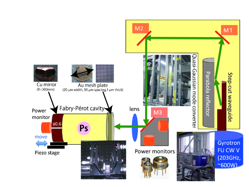
Fig. 1 shows an overall design of our setup to accumulate 203 GHz photons. The setup consists of (1) a 203 GHz gyrotron, (2) quasi-Gaussian mode converter and lens, and (3) Fabry-Pérot cavity.
2.1 Gyrotron
We plan to use a gyrotron ‘Gyrotron FU CW V’, which is fabricated just for our HFS experiment. The gyrotron has 203 GHz resonant frequency and 609 W output power (measured) at the window. The output radiation mode is TE03, which is well-suited to be converted into quasi-Gaussian mode. Since the gyrotron currently has no specific mechanism to change its resonant frequency, tunable frequency is limited by the gyrotron cavity to several handreds of MHz.
2.2 Quasi-Gaussian Mode Converter and Lens
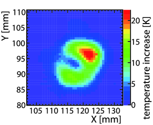
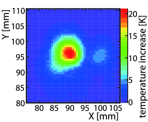
To introduce the gyrotron power to the Fabry-Pérot cavity with high efficiency, input transverse mode to the cavity must be TEM00-like. Our mode converter consists of a step-cut waveguide, ‘Vlasov’ parabola reflector and two parabola mirrors. The design is derived from [2]. Output of the ‘Vlasov’ mirror should be bi-Gaussian at far field, which is converted to Gaussian by two other parabola mirrors. After the converter is located a lens, which controls size, dispersion angle and position of the photon beam at the cavity entrance with 5-axis micro-mover, in order to maximize fraction of the power to enter the cavity. Fig. 2 shows obtained power distributions after the lens, both with and without the Gaussian mode converter. The power distribution with the mode converter is apparently more Gaussian-like.
2.3 Fabry-Pérot Cavity
The Fabry-Pérot cavity consists of a metal-mesh mirror as the input mirror and a copper concave mirror at the other side. Cavity length is precisely controlled by a piezo-walk stage. The mesh parameters are tuned using electromagnetic field simulation to achieve round-trip reflection (already confirmed by measurements) with minimum loss at power introduction. Details of the optimization are described in [3].
For efficient introduction of the power, mode matching between input and inner field is critical. We aim to introduce of the input power into the cavity with the Gaussian converter and the focusing lens by matching beam waist position, beam size, beam position, and the transverse beam shape of the input power to those of the cavity. For the best maching, we monitor the input, reflected, and accumulated power with pyroelectric power monitors located upstream and downstream of the cavity. Final optimization is now ongoing.
3. Source and Detectors
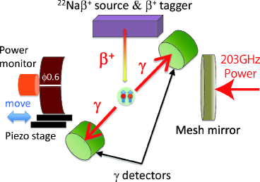
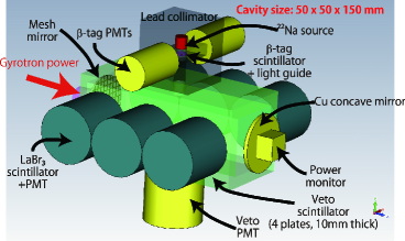
Figure 3 shows the schematic view of the detection system (current plan). A sodium-22 positron source (1 MBq) is located above the cavity. The emitted positron passes through a plastic scintillator which generates a start trigger for timing measurement. The positron then passes through a lead collimator (shielding of prompt background) to reach the cavity. The cavity is filled with isobutan gas which decelerates the positron by multiple scattering. Some of the decelerated positrons form a positronium with an electron in the gas molecule. p-Ps (25% of all Ps) immediately decays to two 511 keV monochromatic photons as well as positron without forming positronium, and o-Ps (75%) decays to three keV photons with longer lifetime of ns. Under the 203 GHz radiation, some of the o-Ps changes into p-Ps by HFS transition.
For detection of the photons from decayed positronium, six LaBr3 crystal scintillator surround the cavity. The LaBr3 scintillators have very good energy resolution of which can efficiently separate 511 keV photons (evidence of HFS transition) from photons from o-Ps decay, and also have good timing resolution of psec to separate prompt events (annihilation). Details of the optimization of source and detector geometry are described in [3].
4. Summary and Plan
We are developing a Ps-HFS direct observation experiment. Using a 203 GHz gyrotron with Gaussian mode converter, quasi-TEM00 high power radiation is efficiently supplied to a Fabry-Pérot cavity which achieves round-trip reflection. Efficiency of power introduction to the cavity is now being optimized. After that, we plan to begin our measurement, which should lead to the first direct HFS transition observation in this summer.
References
- [1] S. Asai et al., this proceedings
-
[2]
I. Ogawa et al., Int. J. Infrared Millimeter Waves, 20 543 (1999),
I. Ogawa et al., Int. J. Electron., 86 1071 (1999) - [3] T. Suehara et al., J. Phys. Conf. Ser., 199 012002 (2010)