Competition between the Modulation Instability and Stimulated Brillouin Scattering in a Broadband Slow Light Device
Abstract
We observe competition between the modulation instability (MI) and stimulated Brillouin scattering (SBS) in a 9.2-GHz broadband SBS slow light device, in which a standard 20-km-long single-mode LEAF fibre is used as the SBS medium. We find that MI is dominant and depletes most of the pump power when we use an intense pump beam at 1.55 m, where the LEAF fibre is anomalously dispersive. The dominance of the MI in the LEAF-fibre-based system suppresses the SBS gain, degrading the SBS slow light delay and limiting the SBS gain-bandwidth to 126 dBGHz. In a dispersion-shifted highly nonlinear fibre, the SBS slow light delay is improved due to the suppression of the MI, resulting in a gain-bandwidth product of 344 dBGHz, limited by our available pump power of 0.82 W.
pacs:
42.65.Dr, 42.65.Es, 42.81.Dp1 Introduction
Slow light refers to the dramatic reduction of the group velocity for optical pulses propagating through a dispersive material [1]. Among various slow light approaches, stimulated-Brillouin-scattering-based slow light in single-mode optical fibres has attracted much interest. Because of the optically controllable delay time and tunability of the bandwidth [2, 3], stimulated Brillouin scattering (SBS) slow light devices have great potential for all-optical applications such as network buffering, optical packet switching, and data synchronization [4, 5]. Fractional delays as large as 3 have been demonstrated recently [6].
In SBS slow light systems, the bandwidth of the device is determined by the linewidth of the resonance. The intrinsic linewidth of the resonance in normal single-mode fibre is 40 MHz (FWHM), which is determined by the decay rate of acoustic phonons in the optical fibre. The data rate in such a system is limited to , which is insufficient for modern optical communication applications. To solve this problem, broadband SBS slow light has been developed, in which the linewidth of the SBS resonance is broadened using a multi-frequency laser source as the pump beam [7, 8].
Herráez et al. [9] first demonstrated tailoring of the pump spectrum using direct modulation of the injecting current of the pump laser. Since then, a number of research groups have successfully broadened the bandwidth of the SBS slow light up to tens of GHz, which is much larger than the intrinsic linewidth of the SBS resonance [10, 11, 6]. However, as we broaden the pump beam spectrum, its power spectral density decreases, thereby suppressing the SBS gain. As a result, the slow light delay, which is proportional to the SBS gain, also decreases. Therefore, the power of the pump beam must be increased to compensate for the reduction of gain at larger bandwidths [12]. As the power increases, other nonlinear optical processes can become important if their response time is fast in comparison to the inverse of the pump beam spectral width. For example, stimulated Raman scattering (SRS) and the modulation instability (MI) have response times of 1 ps[13] and 10 fs[14] respectively, and hence are not affected by pump broadening of several GHz. Eventually, as the bandwidth of the pump is increased and the power increased in proportion, SRS and/or the MI becomes more efficient, potentially robbing pump power and limiting the SBS gain.
Olsson et al. [15] predict that SRS dominates over SBS for pump bandwidths larger than 20 GHz for a gain of 20 dB. No experiment validation of this prediction has been made to the best of our knowledge. On the contrary, our experiment shows that the MI is the dominant competing process in a 9.2-GHz-bandwidth SBS slow light device, which limits the SBS gain-bandwidth product.
In this paper, we study the competing effects and the related limitations on broadband SBS slow light. First, we introduce our broadband SBS slow light experiment and describe the competing processes that can possibly suppress the SBS process. We then verify that SBS is suppressed due to the MI in our broadband SBS device, where a standard single-mode LEAF fibre is used as the SBS medium. We focus here on the LEAF fibre because it is a readily available, relatively inexpensive fibre used in long-haul communication systems and hence is likely to be selected for SBS slow light devices. We also use a wavelength of 1.55 m because it is in the centre of the telecommunication band. As a solution to the problem, we show that the MI and the associated SBS slow light degradation are eliminated by using a dispersion shifted fibre that has normal dispersion at the 1.55 m wavelength window. Finally, we compare the SBS gain-bandwidth-product limit imposed by the MI with the limit imposed by SRS following the approach of Olsson et al.[15] in the LEAF-based system.
2 Broadband SBS slow light and the competing processes
In a broadband SBS slow light device, an optical pulse (the signal) is delayed by interacting with a counterpropagating broadband pump beam via the SBS process. As shown in figure 1, two beams (signal and pump) counterpropagate through the slow-light medium (fibre), where they interact and create low-frequency acoustic waves via electrostriction. These acoustic phonons, in turn, scatter the optical beams via Brillouin scattering. When the frequency of the signal beam is tuned to the Stokes line, that is, downshifted by the Brillouin frequency from the frequency of the pump beam, the opto-acoustic coupling becomes strong, and light from the pump beam is efficiently scattered into the signal beam, inducing a gain resonance and giving rise to a variation in the refractive index in a narrow frequency range around the resonance frequency, which results in a small for the signal beam [16].
Consider an optical pulse propagating through a fibre of length , the transit time is approximately given by [17, 18]
| (1) |
where
| (2) |
is the group index, is the refractive index, is the frequency (in cycles/s) and is the speed of light in vacuum. The delay time in a slow light system is defined as the difference in the transit time through the medium with and without the slow light effect, namely
| (3) |
where and are the group indices with and without slow light effect, respectively.
In our broadband SBS slow light experiment, a current-modulated distributed feedback laser (DFB) is used to increase the linewidth of the SBS resonance. By designing the modulation function, we obtain a square-shaped pump-beam spectrum [6]. The broadened complex SBS gain profile results from the convolution of the intrinsic complex SBS gain spectrum with the intensity spectrum of the input pump beam, which is given by [18, 12]
| (4) | |||||
| (5) |
where
| (6a) | |||||
| , | (6b) |
is the line centre SBS gain factor (a constant determined by the material), is the input power of the pump beam, is the effective cross-section area of the fibre, GHz is the bandwidth of the pump spectrum and is the central frequency of the pump-beam spectrum. Equation (4) is obtained in the so-called undepleted pump approximation, where the pump beam power is constant along the fibre.
The gain profile of the broadened SBS resonance is obtained from the real part of the integral in (5) and is given by
| (7) | |||||
| (8) |
where is the signal beam detuning from resonance. We see that the bandwidth of the resonance is broadened to . However, scales inversely proportional to the bandwidth and more input power is required to compensate for the loss in gain.
The refractive index associated with the SBS process is obtained from the imaginary part of (5) and is given by
| (9) |
where is the refractive index without the SBS process. The group refractive index at zero detuning () is then determined using (2) and (9) to obtain
| (10) |
Because we assume that the pump power does not change over the fibre length , the delay time of an on-resonance signal pulse whose spectral bandwidth is much smaller than that of the broadband SBS resonance is given approximately by
| (11) |
where
| (12) | |||
| (13) |
is the power gain experienced by the probe beam, and and are the output powers of the signal beam with and without the pump beam, respectively. If attenuation in the fibre is considered, the effective length is used in place of length in equations (12) and (13), where is the attenuation coefficient. We see from (11) and (13) that the delay time is proportional to the gain , which is proportional to the pump power and inversely proportional to the pump spectral bandwidth . As a result, we are able to control the delay time by adjusting the pump power.
There are a number of effects that limit the SBS gain , thereby limiting the SBS slow light delay. One ultimate limitation on the SBS slow light delay is SBS gain saturation caused by pump depletion. It takes place when the Stokes beam becomes so strong that most of the power contained in the pump beam is transferred to it. Two different saturation processes are involved. One occurs when the initial probe beam is strong; the amplified probe beam grows quickly and depletes the pump beam even for moderate . The other one takes place when approaches a threshold value , found to be 10 in single-mode fibres [19], where spontaneous Brillouin scattering from thermal fluctuations is amplified and becomes sufficiently large, depleting the pump power even in the absence of a probe beam. When the pump beam is depleted, the undepleted pump assumption is no longer valid. As a result, , and thus the delay time , no longer grow with increasing pump power [19, 16].
Stimulated Raman scattering (SRS) is another competing nonlinear effect in which a pump beam is scattered by high-frequency optical phonons [14]. As a result, the frequency at which the SRS gain resonance occurs is downshifted by 13 THz from the frequency of the pump beam in single-mode fibres. In the presence of a strong pump beam, the Stokes beam initiated by spontaneous Raman scattering is amplified exponentially via the SRS process. When the SRS gain reaches a threshold value of 10 in single-mode fibres [14], most of the pump power is transferred to the Stokes beam.
The SRS gain with a monochromatic pump is typically two orders-of-magnitude smaller than the SBS gain. However, as a result of the fast response time of SRS in single-mode fibres (1 ps) [13], the Raman gain is not affected by the spectral broadening of the pump beam up to the value of 9.2 GHz used in our experiment, whereas the SBS gain is inversely proportional to the bandwidth of the pump as shown in (13). As the pump bandwidth increases, the SBS gain will eventually match the SRS gain, setting the scale for competition between these processes.
MI is yet another process that can compete with the broadband SBS process. MI results from the interplay between the nonlinear Kerr effect and material dispersion. It is a four-wave-mixing process where two copropagating photons of the same frequency are converted into a frequency up-shifted and down-shifted photon pair [14, 20]. As a result, the MI broadens the spectrum of continuous wave (cw) or quasi-cw beams, even turning a continuous wave beam into a train of pulses [21, 22, 20]. In the presence of a strong cw or quasi-cw beam propagating through the fibre, noise components in the vicinity of peaks of the MI gain experience exponential amplification, which leads to the creation of two symmetric spectral side lobes [14, 20]. The gain profile of the MI is given by [14]
| (14) |
where (in cycles/s) is the frequency shift at which the maximum gain is obtained, and is the group velocity dispersion (GVD) parameter. Here [14],
| (15) |
where is the nonlinear parameter. Similar to SRS, the MI is not affected by the pump broadening of 9.2 GHz due to its fast response time (10 fs). We will show that MI is the dominant competing effect in our SBS experiment at high input pump power in a LEAF fibre.
3 Experiment results
In the experiment, as shown in figure 1, a distributed feedback (DFB) laser operating at 1.55 m is used as the pump source. We modulate the injecting current of the DFB laser with a modified triangle function so that the output beam of the DFB laser has a square-shaped spectrum with a bandwidth of 9.2 GHz [6]. The output of the DFB laser is then amplified with an erbium-doped fibre amplifier (EDFA) to provide enough pump power for the broadband SBS process. The EDFA also controls the input pump power and thereby controls the SBS gain. Another DFB laser is used to generate the signal beam, which is tuned to the SBS resonance. To avoid probe-induced SBS gain saturation, the signal beam is attenuated to a power of 2 W before it is injected into the SBS medium, where it counterpropagates and interacts with the pump beam via the SBS process. The amplified and delayed signal is detected at the output. The gain is obtained by measuring the output powers of the signal beam with the pump beam on and off.
We use two different fibres as the SBS medium in the experiment, a 20-km-long LEAF fibre from Corning and a 2-km-long HNLF fibre from OFS. The parameters of the fibres are shown in Table 1. The GVD parameter is measured by the time-of-flight method [24], in which the group velocity as function of the wavelength is measured by recording the transit time for optical pulses to propagate through the fibre with different central wavelengths. The GVD is obtained by dividing the group velocity differences by the wavelength shift. The nonlinear parameter is determined using , where the nonlinear-index coefficient m2/W is used for silica.
| (linear region) | |||||
|---|---|---|---|---|---|
| LEAF | 72 m2 | 12.8 km | 10.5 W-1 | 1.4 W-1km-1 | -5.29 ps2/km |
| HNLF | 11.7 m2 | 1.64 km | 11.1 W-1 | 8.7 W-1km-1 | 0.08 ps2/km |
As one of the most widely used low-cost standard single-mode fibre, LEAF fibre offers great compatibility and would substantially lower the cost of SBS slow light devices, rendering it the first candidate for our experiment. It turns out, however, the zero-dispersion wavelength for the LEAF is not shifted to the transparency window, resulting in a large anomalous dispersion at 1.55 m, which degrades the SBS slow light performance, as shown below.
The SBS gain as a function of is measured for the LEAF fibre and is shown in figure 2a. As is increased from zero to W, first scales linearly with , with a slope of 10.5 W-1, and then starts to saturate and deviate from linear growth at 4, corresponding to an input power 0.4 W (figure 2a). The early saturation of the SBS gain limits the SBS slow light delay.
The saturation behavior shown in figure 2a could be the result of pump depletion due to the SBS process, as we mentioned previously. To rule out this effect, we note the following. First, the saturated value of the gain is 4, which is much smaller than the threshold gain , indicating that saturation is not induced by spontaneous Brillouin amplification. Second, the amplified signal power is only 0.5 mW, which is small in comparison to the input pump power 0.75 W, and is hence much too small to deplete the pump. Moreover, the total power transmitted through the fibre in the direction of the pump beam grows linearly as is increased from 0 to 0.8 W, as shown in figure 2b, which shows directly that the total transmitted power is not depleted.
To explain the early SBS gain saturation at 4, we examine the transmitted pump spectrum passing through the 20-km-long LEAF fibre (Anritsu model MS9710B optical spectrum analyzer). As is increased from zero to 0.8 W, no significant Raman gain is observed (figure 3a). On the other hand, in spectral span of 10 nm, symmetric side lobe structures emerge and grow quickly as increases (figure 3b). At high , the spectrum of the pump is flattened as a result of the emergence of secondary sidebands, and the power is spread into a broad frequency span of 200 GHz. Notice that the pump power transferred to the side lobes is no longer on resonance with the signal beam in the SBS interaction and therefore does not contribute to the SBS gain process.
To determine the amount of power that is transferred to the side lobes, we integrate the power spectral density of the output pump beam and calculate the distracted power as percentages of the total power. As shown in figure 3c, a considerable proportion () of the pump power is transferred to the sidebands when the input power exceeds 0.3 W. We define this point as the threshold for the MI process and the corresponding input pump power as the threshold power in the LEAF fibre. The threshold gain is obtained by (14) to be 10. Note that is close to the location where the early saturation of SBS gain occurs. We also compare the measured frequency shifts of the MI sidelobe peaks with the theoretical prediction using equation (15) and obtain good agreement, as shown in figure 3d. These observations lead us to conclude that the strong saturation of the SBS gain is caused by the MI-induced pump broadening. In conclusion, we find that MI dominates over SBS beyond a threshold pump power of W in the LEAF fibre. In a broadband system where GHz, the threshold pump power corresponds to an SBS gain 3.2, which leads to a limit of 29 GHz or 126 dBGHz on the SBS gain-bandwidth product.
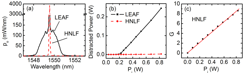
We next turn to the dispersion-shifted HNLF fibre, which has a small and normal dispersion at 1.55 m. Because it is widely known that the MI is suppressed due to phase matching constraints in normally dispersive materials [14, 23, 20], we expect to see suppression of the MI and improvement in the gain-bandwidth product for the broadband SBS slow light with the HNLF fibre. As shown in figure 4, it is found that the MI-induced limit on the SBS gain-bandwidth product is indeed removed. With the same 9.2 GHz broadband pump input, the transmitted pump spectrum through the HNLF shows no significant MI peaks (figure 4a). The power converted into off-resonant frequencies is negligible (figure 4b). As expected, early saturation of the SBS gain in the HNLF does not appear (figure 4c), resulting in a larger SBS gain-bandwidth product of 344 dBGHz, limited by our available pump power of 0.82 W. The result further confirms that MI induced pump broadening is the origin of the early saturation of SBS gain in the LEAF fibre.
4 Discussion
In this section, we compare the relative importance of the two effects that compete with SBS in our broadband SBS slow light system. Following Olsson et al.’s approach, we compare the pump power requirements for the broadband SBS, SRS, and MI processes in the LEAF fibre. Figure 5 shows the input pump power required to obtain a threshold gain of 10 as a function of the bandwidth . The threshold pump power for the SBS process is obtained from equation (12) taking =10 and m/W (obtained from figure 2a), giving
| (16) |
Note that we assume that a weak probe beam is used so that the probe-induced SBS saturation does not appear.
The SRS gain is given by [14]
| (17) |
where m/W [15]. The threshold power required for an SRS gain of 10 is obtained by W. The pump power required for a MI gain 10 is found to be 0.3 W, as mentioned previously.
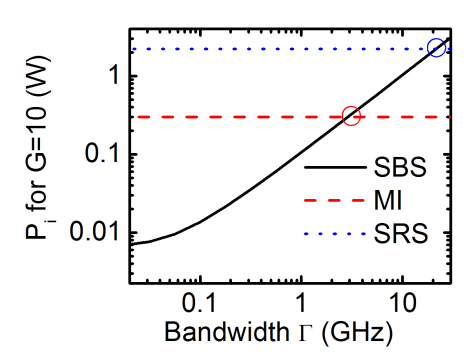
As shown in figure 5, beyond the bandwidth of 3.2 GHz, the LEAF-fibre system hits the MI threshold before it saturates the SBS gain. As a result, MI sets a limit to the SBS gain-bandwidth product. The gain-bandwidth product limit is GHz, or dBGHz using G=10 in the LEAF fibre. Figure 5 also shows that the SRS becomes more efficient than the SBS when the bandwidth goes beyond 22 GHz, and limits the SBS gain-bandwidth product up to 220 GHz or 955 dBGHz. The result is consistent with what Olsson et al. predict [15]. In the LEAF fibre, the SBS gain-bandwidth product is restricted by the tighter MI-induced limit. However, in normally dispersive fibres where the MI is suppressed, SRS becomes the main limitation on the SBS gain-bandwidth product.
In conclusion, we found that in broadband SBS systems, MI dominates in the high pump power region and sets a limit to the SBS gain bandwidth product, which is 126 dBGHz in the LEAF fibre. The SBS suppression and SBS slow light performance is improved in normally dispersive materials.
Acknowledgements
We gratefully acknowledges the financial support of the DARPA Defense Sciences Office Slow Light project.
References
References
- [1] Boyd R and Gauthier D 2009 Science 326(5956), 1074.
- [2] Gonzalez-Herraez M, Song K and Thevenaz L 2005 Appl. Phys. Lett. 87, 081113.
- [3] Okawachi Y, Bigelow M, Sharping J, Zhu Z, Schweinsberg A, Gauthier D, Boyd R and Gaeta A. 2005 Phys. Rev. Lett. 94(15), 153902.
- [4] Tucker R, Ku P and Chang-Hasnain C. 2005 J. Lightwave Technol. 23(12), 4046.
- [5] Bo Z, Yan L, Yang J, Fazal I and Willner A 2007 IEEE Photonics Technol. Lett. 19(14), 1081–1083.
- [6] Cabrera-Granado E, Calderon O, Melle S and Gauthier D 2008 Opt. Express 16(20), 16032–16042.
- [7] Stenner M, Neifeld M, Zhu Z, Dawes A and Gauthier D 2005 Opt. Express 13(25), 9995–10002.
- [8] Shi Z, Pant R, Zhu Z, Stenner M, Neifeld M, Gauthier D and Boyd R 2007 Opt. Lett. 32(14), 1986–1988.
- [9] González Herráez M, Song K and Thévenaz L 2006 Opt. Express 14(4), 1395–1400.
- [10] Song K and Hotate K 2007 Optics letters 32(3), 217–219.
- [11] Yi L, Jaouen Y, Hu W, Su Y and Bigo S 2007 Opt. Express 15(25), 16972–16979.
- [12] Zhu Z, Dawes A, Gauthier D, Zhang L and Willner A 2007 J. Lightwave Technol. 25(1), 201–206.
- [13] Stolen R, Gordon J, Tomlinson W and Haus H 1989 J. Opt. Soc. Am.B 6(6), 1159–1166.
- [14] Agrawal G 2001 Nonlinear fiber optics, Springer, .
- [15] Olsson N and Van Der Ziel J 1987 J. Lightwave Technol. 5(1), 147–153.
- [16] Boyd R 2008 Nonlinear optics, Elsevier Inc., .
- [17] Boyd R, Gauthier D, Gaeta A and Willner A 2005 Phys. Rev.A 71(2), 23801.
- [18] Zhu Z, Gauthier D, Okawachi Y, Sharping J, Gaeta A, Boyd R and Willner A 2005 J. Opt. Soc. Am.B 22(11), 2378–2384.
- [19] Boyd R, Rzaewski K, and Narum P 1965 Phys. Rev.A 42, 5514.
- [20] Dianov E, Mamyshev P, Prokhorov A, and Chernikov S 1989 Opt. Lett. 14(18), 1008–1010.
- [21] Cavalcanti S, Agrawal G, and Yu M 1995 Phys. Rev.A 51(5), 4086–4092.
- [22] Mussot A, Lantz E, Maillotte H, Sylvestre T, Finot C and Pitois S 2004 Opt. Express 12(13), 2838–2843.
- [23] Tai K, Hasegawa A and Tomita A 1986 Phys. Rev. Lett. 56(2), 135–138.
- [24] L Cohen and C Lin 1977 Appl. Opt. 16, 3136-3139.