Non-linear thermoelectrics of molecular junctions with vibrational coupling
Abstract
We present a detailed study of the non-linear thermoelectric properties of a molecular junction, represented by a dissipative Anderson-Holstein model. A single orbital level with strong Coulomb interaction is coupled to a localized vibrational mode and we account for both electron and phonon exchange with both electrodes, investigating how these contribute to the heat and charge transport. We calculate the efficiency and power output of the device operated as a heat to electric power converter and identify the optimal operating conditions, which are found to be qualitatively changed by the presence of the vibrational mode. Based on this study of a generic model system, we discuss the desirable properties of molecular junctions for thermoelectric applications.
pacs:
84.60.Rb 85.65.+h, 85.35.Gv, 85.35.-p,I Introduction
The field of single-molecule electronics has been expanding rapidly during recent years, as techniques to electrically contact and control single molecules in a transport junction have improved Reed et al. (1997); Stipe et al. (1998); Park et al. (1999); Kubatkin et al. (2003); O’Neill et al. (2007). By studying the electric current through the molecule as function of the applied voltage-bias, spectroscopic information can be extracted Stipe et al. (1998). In setups with a gate-electrode, which can be used to control the electrostatic potential on the molecule, a detailed spectroscopy can be performed Park et al. (1999); Kubatkin et al. (2003); O’Neill et al. (2007). By applying a temperature-bias and measuring the induced electric current or voltage, additional information can be extracted, such as the type of carriers (holes / electrons) dominating transport Paulsson and Datta (2003). This emerging field of molecular thermoelectrics Reddy et al. (2007); Baheti et al. (2008); Finch et al. (2009); Murphy et al. (2008); Koch et al. (2004) is also interesting for applications. Molecules have been predicted to be particularly efficient for conversion of heat into electric energy Finch et al. (2009); Murphy et al. (2008) (or analogously for cooling, using electric energy to pump heat), the reason being their very sharp electronic resonances when weakly coupled to electrodes Murphy et al. (2008). This is similar to the large thermoelectric efficiency of e.g., semi-conducting nanowires with highly peaked densities of states Lin et al. (2000).
Most theoretical works on meso- and nano-scale thermoelectrics have focused on the linear, equilibrium regime, where one operates close to the small voltage which exactly cancels the current induced by the small thermal bias . Here the thermopower (or Seebeck coefficient) is the decisive quantity, where () is the (thermal) conductance. A large efficiency of the device operated as a heat to electric energy converter is then related to a large dimensionless thermoelectric figure of merit , where is the operating temperature and the thermal conductance. In bulk systems, is normally limited by the Wiedemann-Franz law, stating that is a system independent constant. However, the Wiedemann-Franz law is a result of Fermi-liquid theory and breaks down in mesoscopic and nanoscopic systems, e.g., due to large Coulomb interaction, as has been demonstrated for quantum dots Boese and Fazio (2001) and metallic islands Kubala et al. (2008), allowing much larger values of to be reached. As , the efficiency approaches the ideal Carnot value Murphy et al. (2008).
However, in the linear regime, , the efficiency stays low even if can be made very large: . The non-linear thermoelectric properties of molecular junctions are therefore of great interest. Recent experiments Reddy et al. (2007) probing the thermopower of thiol end-capped organic molecules showed non-linearities in the measured already at . Earlier measurements of thermopower in metallic island single-electron transistors even displayed a change of the sign of the thermopower for very large Staring et al. (1993).
In the interesting regime of sharp electronic resonances, the electron tunnel coupling is small and the main factor limiting the efficiency of molecular energy converters is expected to be the heat current from phonon exchange with rate Murphy et al. (2008). Nonetheless, to our knowledge, its effect has this far not been systematically investigated. Only by making the tunnel coupling larger, , the phonon contribution to the heat current becomes negligible. In this case, however, the efficiency becomes instead limited by the large electronic life-time broadening of the molecular resonances. The thermoelectric efficiency in this limit of coherent transport was studied very recently in the non-linear regime Bergfield et al. (2009) using both a many-body transport approach and a (non-interacting) approach based on Hückel theory. Except for the latter work and a few others Koch et al. (2004); Murphy et al. (2008), most theoretical studies of molecular thermoelectrics have focused on non-interacting models, using a Landauer type approach. However, in the regime of weak tunnel coupling between molecule and electrodes, intra-molecular interactions typically constitute the largest energy scales of the problem.
In this paper, we calculate the thermoelectric efficiency and converted electric power of a molecular device, including a single dominant molecular orbital, strong Coulomb interaction and coupling to a discrete vibrational mode, as well as coupling to lead phonons and lead electrons. Importantly, we include on equal footing the phonon and electron contributions to the heat current, both of which contribute in establishing the stationary occupation of the molecular vibrational mode. The Coulomb repulsion and electron-vibration coupling on the molecule are treated non-perturbatively in the limit of weak electron and phonon exchange in which thermoelectric efficiency is high. A central finding is that optimal thermoelectric operation typically is achieved in the non-linear, non-equilibrium regime. Here concepts of figure of merit and thermopower are no longer meaningful and the molecular occupancies, efficiency and output power must be explicitly calculated. The paper is organized as follows: Sect. II introduces the dissipative Anderson-Holstein model and the thermoelectric transport equations. In Sect. III we present results for the efficiency and output power as function of the applied bias voltage and energy of the molecular orbital dominating transport. The heating of the molecule is analyzed in Sect. IV and the optimal choice of molecule and junction parameters is discussed in Sect. V. Section VI summarizes and provides an outlook.
Throughout the paper we set , where is Planck’s constant, the Boltzmann constant and the electron charge.
II Model and thermoelectric transport theory
Despite polarization and screening effects in molecular junctions Kaasbjerg and Flensberg (2008), the electronic level-spacing in molecular devices is typically large compared to applied voltage- and temperature-bias. We therefore restrict our attention to a single molecular orbital dominating transport. In fact, the thermoelectric properties have also been predicted to be optimal in this case Mahan and Sofo (1996); Humphrey and Linke (2005). However, the quantized vibrational modes, which couple to the charge localized on a molecular device, cannot be neglected Park et al. (2000); Pasupathy et al. (2005); Osorio et al. (2007). The vibrations additionally couple to bulk phonon modes of the electrodes Braig and Flensberg (2003). The goal of this paper is to clarify the importance of these excitations, characteristic of a molecular device, for the thermoelectric properties. We consider a thermoelectric junction as sketched in Fig. 1. Its basic physics is captured by the following dissipative Anderson-Holstein model Hamiltonian , where
| (1) | |||||
| (2) | |||||
| (3) | |||||
The molecular Hamiltonian, , describes a spin-degenerate orbital level (operator for spin-projection ) with energy and Coulomb repulsion . The electron number , with , is linearly coupled to the vibrational coordinate of the harmonic mode of frequency (operator ). The dimensionless electron-vibration coupling is the shift of the vibrational potential as the molecule is charged, measured in units of the vibrational zero-point amplitude. The reservoir Hamiltonian, , describes the combined electron and phonon degrees of freedom in the two reservoirs, conveniently referred to as the hot () and cold () electrodes. Non-interacting reservoir electrons with energy are created (annihilated) by (); () are the corresponding phonon operators for an electrode phonon mode with frequency . In each electrode electrons and phonons are assumed to be in equilibrium with temperatures and respectively. The coupling between the reservoirs and the molecule is described by the Hamiltonian , where the first term describes tunneling of electrons with amplitude and the second term couples the molecular and electrode vibrational coordinates with (in general energy-dependent) amplitude . In view of the thermoelectric efficiency we consider the case where both couplings are weak, i.e., we want a small tunnel broadening and a small heat current carried by the phonons. Therefore, can be treated perturbatively below. The electron-electron interaction and electron-vibration coupling on the molecule are however allowed to take arbitrary values, which is a crucial aspect for addressing the important regime and .
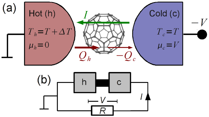
We consider the thermoelectric junction in Fig. 1(a) operated as a heat to electric power converter. One electrode is heated (referred to as hot (h)) with the other electrode (referred to as cold (c)) kept at the ambient temperature. The hot electrode is grounded (chemical potential measured relative to the electrode Fermi levels at zero bias) and a (negative) voltage is applied to the cold electrode (). For simplicity we assume the capacitances associated with the tunnel junctions to both electrodes to be equal, resulting in a voltage-dependence of the molecular orbital, . We note that in an actual device which also makes use of the converted power, the voltage is not applied, but rather controlled by the temperature-bias and the resistance of the external circuit, see Fig. 1(b).
To formulate the transport equations, the linear coupling term in (1) is first eliminated by a standard transformation Lang and Firsov (1962); Flensberg (2003), which leads to a renormalization of the onsite and charging energies: , . After this transformation the eigenstates of are easily found to be given by , where is the electronic state and denotes the vibrational excitation number. The corresponding eigenenergies are with , and . Furthermore, the electron tunnel amplitude is renormalized to , thereby incorporating the Franck-Condon factors for electron tunneling. The resulting transport characteristics under an applied voltage-bias have been analyzed in many works, see e.g., Flensberg (2003); Mitra et al. (2004); Leijnse and Wegewijs (2008). We note that in principle the additional coupling to reservoir phonon modes requires a more involved transformation, leading to more complicated expressions for the renormalized parameters Braig and Flensberg (2003). These corrections can be neglected in the regime considered here, where the coupling between the reservoir phonons and the molecular vibrational mode is weak.
As mentioned above, the maximum efficiency of energy conversion is expected in the limit of weak electron tunneling Murphy et al. (2008) and weak coupling between molecular- and electrode vibrations: . Here the rate for electron tunneling involving electrode is , where is the density of states, which is assumed energy independent (wide band limit). The relevant rate for phonon exchange with electrode is , with defined by . Here the phonon density of states, , and the coupling strength, , are in general energy-dependent. However, in the weak coupling limit only their value at enters into the problem due to the selection rule in lowest order perturbation theory in the coupling to electrode phonons (see the expression (5) for the rate matrix below). In the regime of non-linear temperature- and/or voltage-bias addressed in this paper, the molecular density matrix is not known a priori and needs to be calculated. For the weak coupling considered here this can be done using a standard master equation approach. We can neglect contributions from non-diagonal elements of the density matrix, since the molecular states in our model are non-degenerate on the scale set by the rates () and spin-degeneracy does not lead to off-diagonal contributions. We note that this holds only in the weak coupling limit where the transport rates are evaluated to lowest order perturbation theory in and Leijnse and Wegewijs (2008). The transition rates for electron tunneling () and phonon exchange () can then be calculated from Fermi’s golden rule Mitra et al. (2004); Segal (2006):
| (4) | |||||
| (5) |
Here is a Franck-Condon factor Flensberg (2003), the spin-projection onto the -axis of state , which has electron number , and and are respectively the Fermi- and Bose distribution functions of lead with electro-chemical potential . The stationary state master equation to be solved for the occupations then reads
| (6) | |||||
| (7) |
where Eq. (7) expresses probability normalization. At this point, we note that the interplay of charge and phonon tunneling is still non-trivial, as they do ”interact” via the vibrational occupation number. A finite electric current tends to highly excite the vibrational mode, leading to high effective molecular temperatures (see also Fig. 3(c)) and even clear deviations from an equilibrium (Boltzmann) shape of the distribution. This effect is particularly pronounced when the electron-vibration coupling is not too large, . The phonon current, on the other hand, tends to thermalize the vibration towards a temperature, that depends only on the temperatures of the hot () and cold () lead and the relative size of the couplings and . However, through the excitations created by the electric current, the phonon current acquires an indirect dependence on both voltage and level position. Therefore accurate calculation of the non-equilibrium molecular state accounting for both electron and phonon effects is crucial.
The electric current, , and heat current, , going out of lead , are given by
| (8) | |||||
| (9) | |||||
where and . The electron current matrix is similar to (4), but includes only processes involving reservoir and a plus / minus sign for processes adding electrons to the molecules (first term in (4)) / removing electrons from the molecules (second term in (4)). Analogously, the heat current matrices, and , are similar to (4) and (5), respectively, but including only processes involving reservoir and with the rate multiplied by the energy of the tunneling electron (measured relative to ) or phonon. We note that there is in general some ambiguity associated with the definition of the heat current, see Wu and Segal (2009), which however does not matter in the weak coupling limit discussed here.
Beyond the linear regime, thermopower and figure of merit are no longer suitable quantities and we instead directly calculate the efficiency of the energy converter as follows. Driven by the thermal bias, electrons can gain potential energy by tunneling from the hot to the cold electrode via the molecule. The resulting electric output power is , where . The input heat power, required to maintain the temperature bias, is equal to the heat current, , flowing out of the hot electrode. The efficiency is thus given by
| (12) |
Note that there is no conservation of the stationary heat current, as there is for the electric current, . Instead the first law of thermodynamics guarantees that .
III Optimal bias voltage and level position
We start by studying the efficiency and output power at fixed thermal bias, here chosen to be , as function of applied voltage-bias and level position . The efficiency of a single level quantum dot (spin-less electrons and no vibrational mode) was studied in Esposito et al. (2009), where it was shown that the ideal Carnot efficiency is reached in the equilibrium limit of vanishing current, requiring the Fermi functions to be equal, , defining a line in the plane: . In Fig. 2 this equilibrium line corresponds to the boundary of the white areas. However, along this line also the output power vanishes (corresponding to reversible, infinitely slow operation without entropy loss). For vanishing couplings to the phonon mode, and , we recover this result in the non-interacting limit, , as well as for very strong interactions, . In the intermediate regime, the efficiency is slightly reduced.
Switching on the electron-vibration coupling, but keeping , the efficiency is decreased and never reaches the ideal value ( for ), see Fig. 2(a). In fact, vanishes close to the zero electric current line (boundary of the white area), the reason being that, in contrast to the single-level discussed above, the heat current does not vanish completely when the charge current does. Inside the white area the current has been reversed by a too large voltage-bias and flows from high- to low-biased electrode and therefore does not accomplish any useful electric work (note that this regime can not be reached in the thermoelectric circuit of Fig. 1(b)).

The maximal efficiency is reached in the non-linear regime when the level is far above the Fermi edges of both leads. In this case electron transport involves very few thermally excited states in the heated electrode (tail of the Fermi function) and electron-induced vibrational excitations are exponentially suppressed, minimizing electronic heat loss. However, in this regime the current is highly suppressed, leading to a very small output power, see Fig. 2(d). Additionally, even a small coupling to the substrate phonons, in Fig. 2(b), drastically decreases the efficiency in this low-current regime, while having a much smaller effect in the regime where the current is larger ( is smaller). Thus, already a weak coupling to substrate phonon modes, , drastically changes the ideal operating conditions for maximum efficiency by introducing a heat loss which depends only weakly on and (the dependence is indirect, through the vibrational occupations). When the coupling to the substrate phonons becomes comparable to the tunnel coupling, in Fig. 2(c), the efficiency is significantly decreased also in the high current regime. The output power, shown in Fig. 2(d) for the parameters used in (b), depends only weakly on and is maximal for and .
IV Temperature dependence and molecular heating
Next we fix the level position to a value with both large power and efficiency, , and vary instead and . The resulting efficiency and output power is shown in Fig. 3(a) and (b) respectively, for the same parameters as in Fig. 2(b).
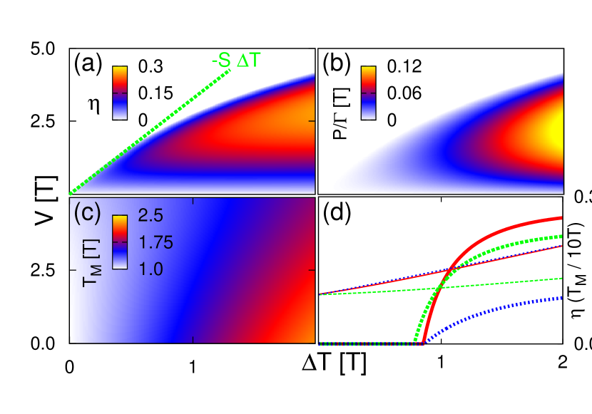
As above, a too large voltage-bias compared to the temperature-bias reverses the current and no useful electric work is accomplished (white areas). The non-linear thermopower can be defined through at , i.e., is the finite voltage needed to compensate the temperature-bias and give zero electric current. Thus, is given by the slope of the line which passes through zero voltage at zero temperature-bias and hits the edge of the white areas at in Fig. 3(a) and (b). For large temperature-bias there are clear deviations from the linear response thermopower, , given by the slope of the green dashed line in Fig. 3(a).
As expected, the efficiency and (even more so) the power is increased by an increased temperature-bias. Figure 3(a)–(b) shows the dependence on the temperature-bias over a wide range, all the way up to . Such large temperature-bias could be obtained if the device is operated at low temperatures. In applications, however, is most likely room temperature and junction stability limits operation to lower relative temperature-bias (e.g., would mean K, which is a realistic value). However, it is actually possible to keep the (non-equilibrium) molecular temperature, , much lower than the average electrode temperature, , allowing operation at higher temperature-bias.
To calculate we use an idea suggested in Galperin et al. (2007) and couple an additional phonon bath (”thermometer”) very weakly to the molecule. The temperature of the thermometer bath is varied and is defined as the bath temperature where the heat current between this bath and the molecule vanishes. Figure 3(c) shows as function of and , where it is seen that for small voltages exceeds the average electrode temperature . A larger voltage-bias, however, reduces the non-equilibrium electron current and approaches . Still, it is desirable to reduce further, thereby allowing operation at higher without breaking the molecule. In designing molecular thermoelectric junctions it is therefore important to choose the electrode material and molecular anchoring groups such that the molecular vibration couples more strongly to the substrate phonons of the colder electrode (). This is shown in Fig. 3(d), where (red solid lines), (green dashed lines) and (blue dotted lines). The asymmetric phonon coupling significantly reduces (thin lines) by preventing phonons from accumulating on the molecule: they enter slowly () and exit quickly (). However, the asymmetry has a rather small effect on the efficiency (thick lines) since heat is still prevented from ”leaking” through the molecule via the phonons as long as stays small compared to . In contrast, with also large the efficiency goes down much more, and goes up (the red solid and blue dotted lines for still show a very small difference: the electron tunneling and substrate phonon couplings drive the system toward slightly different molecular temperatures, causing to depend on the ratio ). In realizing the mechanical coupling asymmetry , it is important keep the electronic tunnel coupling symmetric. Introducing an asymmetry in the electron tunnel couplings, , while keeping fixed, reduces the efficiency since the current level is set by the smallest coupling, while the phonon leakage current depends only weakly on and (only indirectly through the vibrational occupations).
V Optimal thermoelectric junctions
Comparing Fig. 3(a) and (b), we reach an important result for optimizing molecular thermoelectric junctions, namely that for a given temperature-bias, maximum efficiency and maximum output power is achieved at almost the same voltage-bias. This is also seen in Fig. 4, where (a) shows the maximum efficiency, , and (b) the efficiency at maximum power , both obtained by adjusting the voltage at given thermal bias .
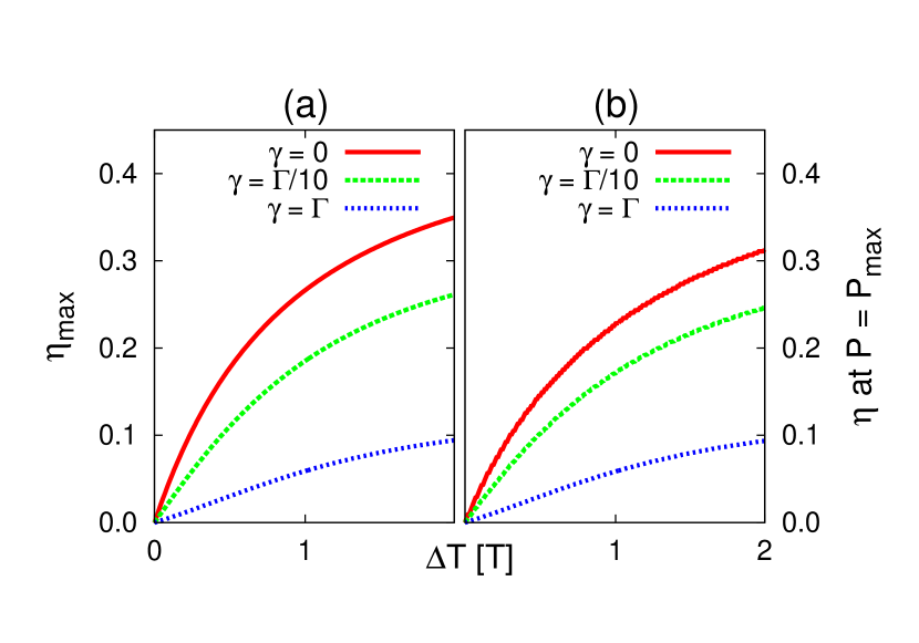
For non-zero coupling to substrate phonons the maximum efficiency and the efficiency at maximum output power are very close. The reason is seen from the relation , where () is the electron (phonon) contribution to the heat current. Since only has a weak (indirect) dependence on the voltage-bias, and can be simultaneously maximized by adjusting the bias when the phonon heat loss dominates (). As Fig. 3 and Fig. 4 shows, this holds approximately also when .
When the electron-vibration coupling becomes strong, , the tunnel amplitudes involving the vibrational ground state become suppressed (Franck-Condon blockade Koch and von Oppen (2005)). This reduces both the efficiency and output power since the current is decreased. Additionally, heat dissipation is increased since transport through excited vibrational states is favored, the typical energy transferred to the vibrational mode by a tunneling electron being given by the classical displacement energy, . This is shown in Fig. 5(a) and (b), where (cf., Fig. 3(a) and (b)).
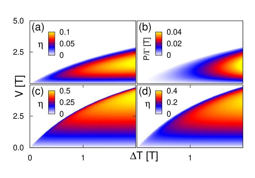
Similarly, a smaller electron-vibration coupling enhances the efficiency, see Fig. 5(c), where .
In choosing ( meV assuming room temperature) we have investigated the influence of a rather high energy vibrational mode. Molecules often also have vibrational modes with much lower frequency, down to a few meV, especially when contacted to electrodes by linker wires Seldenthuis et al. (2008). However, as is shown in Fig. 5(d), where , a low-energy vibrational mode leads to a much smaller decrease of compared to the ideal case of no vibrational mode, as long as is not too large. The reason is simply that a low frequency mode essentially can be seen as a broadening of the electronic resonance of width , setting the scale for additional heat loss from electron tunneling compared to the case of no vibrational mode. Almost all decrease in efficiency in this case comes from the coupling to substrate phonon modes. In contrast, a vibrational mode with a frequency much larger than the involved temperature- and voltage-bias, does not contribute at all to electron or heat transport (other than through the trivial shift of the electronic parameters , and through the electron-vibration coupling).
Finally, we mention that in the simple model analyzed here, the strength of the Coulomb interaction does not play a crucial role. In the presence of a coupling to substrate phonons, reducing leads to a somewhat larger efficiency (and output power) as the electric current is increased by the presence of another ”transport channel”.
VI Conclusions
We have analyzed the efficiency and output power of a non-linear molecular thermoelectric device operated as a power converter. Accounting for the molecular vibration and its coupling to substrate phonons turned out to be crucial in comparison with results for quantum dot models without these, as it qualitatively changes the operating conditions for optimal efficiency away from the equilibrium regime. By investigating a generic model system we can now identify some basic criteria for efficient molecular energy converters:
(i) The coupling between substrate phonon modes and molecular vibrations should be asymmetric and minimal. Coupling more strongly to the colder lead reduces the molecular temperature and allows operation at higher temperature-bias, improving efficiency and output power.
(ii) The electron tunnel couplings should be symmetric, . Furthermore, they should be small as to minimize the life-time broadening, but still larger than the phonon coupling, .
(iii) The local electron-vibration coupling energy should be small compared to the zero-point energy of the vibrational mode (). This is most crucial for vibrational modes with frequencies around the operating temperatures and voltages. Modes with much higher frequencies do not contribute at all, and those with much lower frequencies only contribute to the heat loss through the coupling to substrate phonons.
(iv) Ideal operating conditions for high efficiency and power is achieved when the conducting orbital energy is at a few from the Fermi edges of the electrodes ( meV at room temperature). Control of the thermopower by adding electron donating or withdrawing groups to benzenedithiol molecules, thereby shifting the position of the HOMO and LUMO, was recently demonstrated Baheti et al. (2008). The temperature-bias should be chosen as high as is allowed by molecular stability and the heat source. The ideal voltage-bias depends on the other parameters, but is nearly the same when optimizing output power as when optimizing efficiency. Additionally, the efficiency at maximum power is very close to the maximum efficiency.
The general insights obtained in this exhaustive study of the most basic molecular thermoelectric model can serve as a guide for more complex molecular modeling, incorporating multiple vibrational modes, multiple electronic states, breakdown of the Born-Oppenheimer picture (pseudo Jahn-Teller mixing Reckermann et al. (2008)), etc. In general, one expects deviations from a single-orbital model to give a less efficient energy-converter, as additional heat is lost by population of excited states. It might however be possible to find special circumstances under which excited states can instead be desirable, e.g., by effectively cooling the vibrational mode. Atomistic studies of specific configurations of molecules, anchoring groups and electrodes may identify suitable systems which satisfy the above criteria and thereby further assist in advancing the chemical engineering of molecular thermoelectric junctions. For device applications, engineering of molecular monolayer devices, rather than ones based on a single molecule, presents a challenge to supramolecular chemistry, nanodevice fabrication and surface science.
ACKNOWLEDGMENTS
We acknowledge financial support from the DFG under Contract No. SPP-1243 (M. L., M. W) and the European Union under the FP7 STREP program SINGLE (M. L., K. F.). This work was carried out partly in the Danish-Chinese Centre for Molecular Nano-Electronics supported by the Danish National Research Foundation.
References
- Reed et al. (1997) M. A. Reed, C. Zhou, C. J. Muller, T. P. Burgin, and J. M. Tour, Science 278, 252 (1997).
- Stipe et al. (1998) B. C. Stipe, M. A. Rezaei, and W. Ho, Science 280, 1732 (1998).
- Park et al. (1999) H. Park, A. K. L. Lim, A. P. Alivisatos, J. Park, and P. L. McEuen, Appl. Phys. Lett. 75, 301 (1999).
- Kubatkin et al. (2003) S. Kubatkin, A. Danilov, M. Hjort, J. Cornil, J. Brédas, N. Stuhr-Hansen, P. Hedegård, and T. Bjørnholm., Nature 425, 698 (2003).
- O’Neill et al. (2007) K. O’Neill, E. A. Osorio, and H. S. J. van der Zant, Appl. Phys. Lett. 90, 133109 (2007).
- Paulsson and Datta (2003) M. Paulsson and S. Datta, Phys. Rev. B 67, 241403(R) (2003).
- Reddy et al. (2007) P. Reddy, S.-Y. Jang, R. A. Segalman, and A. Mujamdar, Science 315, 1568 (2007).
- Baheti et al. (2008) K. Baheti, J. A. Malen, P. Doak, P. Reddy, S.-Y. Jang, T. D. Tilley, A. Mujamdar, and R. A. Segalman, Nano Lett. 8, 715 (2008).
- Finch et al. (2009) C. M. Finch, V. M. García-Suárez, and C. J. Lambert, Phys. Rev. B 79, 033405 (2009).
- Murphy et al. (2008) P. Murphy, S. Mukerjee, and J. Moore, Phys. Rev. B 78, 161406(R) (2008).
- Koch et al. (2004) J. Koch, F. von Oppen, Y. Oreg, and E. Sela, Phys. Rev. B 70, 195107 (2004).
- Lin et al. (2000) Y.-M. Lin, X. Sun, and M. S. Dresselhaus, Phys. Rev. B 62, 4610 (2000).
- Boese and Fazio (2001) D. Boese and R. Fazio, Eur. Phys. Lett. 56, 576 (2001).
- Kubala et al. (2008) B. Kubala, J. König, and J. Pekola, Phys. Rev. Lett. 100, 066801 (2008).
- Staring et al. (1993) A. A. M. Staring, L. W. Molenkamp, B. W. Alphenaar, H. van Houten, O. J. A. Buyk, M. A. A. Mabesoone, C. W. J. Beenakker, and C. T. Foxon, Eur. Phys. Lett. 22, 57 (1993).
- Bergfield et al. (2009) J. P. Bergfield, M. Solis, and C. A. Stafford (2009), arXiv:1003.2000.
- Kaasbjerg and Flensberg (2008) K. Kaasbjerg and K. Flensberg, Nano Lett. 8, 3809 (2008).
- Mahan and Sofo (1996) G. D. Mahan and J. O. Sofo, Proc. Natl. Acad. Sci. U. S. A. 93, 7436 (1996).
- Humphrey and Linke (2005) T. E. Humphrey and H. Linke, Phys. Rev. Lett. 94, 096601 (2005).
- Park et al. (2000) H. Park, J. Park, A. K. L. Lim, E. H. Anderson, A. P. Alivisatos, and P. L. McEuen, Nature 407, 57 (2000).
- Pasupathy et al. (2005) A. N. Pasupathy, J. Park, C. Chang, A. V. Soldatov, S. Lebedkin, R. C. Bialczak, J. E. Grose, L. A. K. Donev, J. P. Sethna, D. C. Ralph, et al., Nano Lett. 5, 203 (2005).
- Osorio et al. (2007) E. A. Osorio, K. O’Neill, N. Stuhr-Hansen, O. F. Nielsen, T. Bjørnholm, and H. S. J. van der Zant, Adv. Mater. 19, 281 (2007).
- Braig and Flensberg (2003) S. Braig and K. Flensberg, Phys. Rev. B 68, 205324 (2003).
- Lang and Firsov (1962) I. G. Lang and Y. A. Firsov, Sov. Phys. JETP 16, 1301 (1962).
- Flensberg (2003) K. Flensberg, Phys. Rev. B 68, 205323 (2003).
- Mitra et al. (2004) A. Mitra, I. Aleiner, and A. J. Millis, Phys. Rev. B 69, 245302 (2004).
- Leijnse and Wegewijs (2008) M. Leijnse and M. R. Wegewijs, Phys. Rev. B 78, 235424 (2008).
- Segal (2006) D. Segal, Phys. Rev. B 73, 205415 (2006).
- Wu and Segal (2009) L.-A. Wu and D. Segal, J. Phys. A: Math. Theor. 42, 025302 (2009).
- Esposito et al. (2009) M. Esposito, K. Lindenberg, and C. van den Broeck, Eur. Phys. Lett. 85, 60010 (2009).
- Galperin et al. (2007) M. Galperin, A. Nitzan, and M. A. Ratner, Phys. Rev. B 75, 155312 (2007).
- Koch and von Oppen (2005) J. Koch and F. von Oppen, Phys. Rev. Lett. 94, 206804 (2005).
- Seldenthuis et al. (2008) J. S. Seldenthuis, H. S. J. van der Zant, M. A. Ratner, and J. M. Thijssen, ACS Nano 2, 1445 (2008).
- Reckermann et al. (2008) F. Reckermann, M. Leijnse, M. R. Wegewijs, and H. Schoeller, Eur. Phys. Lett. 83, 58001 (2008).