Using electrowetting to control interface motion in patterned microchannels
Abstract
We use mesoscale simulations to demonstrate the feasibility of a novel microfluidic valve, which exploits Gibbs’ pinning in microchannels patterned by posts or ridges, together with electrowetting.
As fluidic devices become smaller there is a need for simple and robust ways to control the motion of fluids moving through them. Several way to arrest capillary filling have been developed CH-04 ; SYHOS-08 ; MS-06 ; BB-98 ; HFE-99 ; DGLSK-99 . These are mainly based on using hydrophobic patches CH-04 ; SYHOS-08 ; MS-06 or narrow hydrophobic channels to arrest the flow BB-98 ; HFE-99 ; DGLSK-99 . In the first case filling is restarted by an electric field which decreases the contact angle, while in the second a driving pressure is applied. In this paper we use numerical simulations to motivate an alternative mechanism for creating a microfluidic valve. We show that placing obstacles at relevant positions along a microchannel, and addressing them by an electrowetting potential applied at the position of the interface QB-01 , can allow capillary filling LW to be halted and restarted reversibly.
If a microchannel is brought into contact with a fluid, and the contact angle between the surface and the fluid, , is less than 90∘, the fluid will move into the channel LW . This is the well-known process of capillary filling. However, if there are obstacles to the flow, such as micron-scale ridges or posts on the surface, the advancing front can pin for contact angles greater than a certain threshold value (), thus halting the filling. For a slowly moving interface the pinning can be understood in terms of the Gibbs’ criterion Gibbs which states that an interface remains pinned to a corner as long as it makes an angle smaller than with each of the dry surfaces meeting at the corner. As the interface is pulled along the channel by the capillary forces, it may not reach the required angle to wet the surface of the obstacles, and hence the filling is arrested.
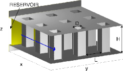
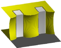
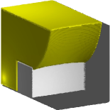
We consider first the geometry shown in Fig. 1a. Posts of square cross section and spacing reach across a channel of height . Flow is along the direction and we consider a channel sufficiently wide that the effect of the side walls may be neglected. Fig. 1b depicts a pinned configuration for this geometry. Although the front is pulled along the top and bottom walls of the channel, for sufficiently large contact angles it does not move far enough to start wetting the dry face of the posts. For the threshold contact angle below which flow is possible is . This value is independent of the channel height because the walls act independently MY-09 . As decreases below unity, increases to as . Hence a suitable choice of allows to be tuned as required.
(a)
 (b)
(b)
 (c)
(c)
Electrowetting QB-01 , the application of an electric potential to a microchannel, is a robust method of changing the contact angles by tens of degrees. Hence one might expect that the application of an electrowetting potential can rather easily move the system between the pinned and the filling regimes, thus allowing control of the motion of the capillary front. In this letter we present simulations of capillary filling in a patterned microchannel showing, in particular, how switching between contact angles above and below can be used to halt and restart capillary filling. Before presenting our results we first outline the numerical approach we use.
As we are considering micron length scales it is appropriate to describe the system using a mesoscale algorithm. We consider a binary fluid with components and , say, which in equilibrium is described by minimising the free energy functional
| (1) |
where is the local total density of the and components (), is the order parameter and is the lattice velocity , where is the lattice spacing and is the simulation time step. The first integral in Eq. (1), taken over the total volume , controls the bulk properties of the system. The terms in give coexistence of phases with . The energy cost of an interface between the two phases is modeled by the derivative term, with related to the surface tension. The term in controls the compressibility of the fluid. The integral over the solid-fluid interface in Eq. (1) accounts for the wetting properties of the solid surfaces C-77 . The surface field can be used to tune the equilibrium contact angle.
The hydrodynamics of the fluid is described by the Navier-Stokes equations for the density and the velocity field together with a convection-diffusion equation for the binary order parameter
| (2) | |||
| (3) | |||
| (4) |
In Eq. (3) is the viscosity of the fluid and in Eq. (4) is a mobility coefficient. The pressure tensor and the chemical potential which appear in Eqs. (3) and (4), are calculated from the free energy (1).
We have chosen to use a two-component binary fluid as a model system. This is because modeling capillary filling correctly using a liquid-gas diffuse interface model is computationally very demanding because of unphysical motion of the interface due to evaporation-condensation effects EC . However our results are equally applicable to a physical system where a liquid displaces a gas as the important physical parameters are the viscosities, not the densities, of the fluid components. Therefore we shall use the natural terminology ‘liquid’ and ‘gas’ for the displacing and displaced fluid from now on. The equations of motion are solved using a lattice Boltzmann algorithm LB . Full details are given in Refs. detail ; Halim-08 . In particular Halim-08 shows that this approach gives excellent agreement with analytic results for capillary filling in smooth microchannels.
For our first simulations we investigate the microchannel geometry shown in Fig. 1a. Measuring distances in lattice units, the simulation box is of size and we take periodic boundary conditions in the y-direction. The height of the channel , the separation of the posts , and the posts are of width and lie between and , and , etc. At the beginning and end of the channel are liquid and gas reservoirs respectively, connected in order to equalise the pressure. The simulations commence with the interface at and with the elctrowetting potential switched off.
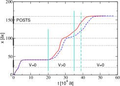
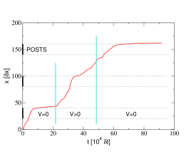
The subsequent position of the interface (recorded in the centre of channel) as a function of time is shown in Fig. 1c. The zero potential equilibrium contact angle of the channel is chosen to be . This is greater than so the advancing front is pinned at the first row of posts, in the configuration reported in Fig. 1b. At the contact angle of the channel is decreased to , corresponding to the application of an electrowetting field. Filling restarts immediately and the interface advances. It is accelerated (by the increased hydrophilic surface area) as it passes the second row of posts and then slowed as it reaches the trailing edges of the posts, but is not pinned MY-09 . We have checked that it also passes the third row of posts if is held at 30∘.
However, in the results presented in Fig. 1c, the equilibrium contact angle is switched back to when the advancing front reaches the middle point between the second and the third posts. This leads to pinning, explicitly showing the possibility of stopping the imbibition of the channel at a prespecified position.
As a more stringent test we also simulated a channel with six rows of posts switching between and . Pinning and subsequent depinning when the electrowetting potential was activated was observed at each post.
The broken line in Fig. 1c compares a similar simulation, but with the contact angle on the channel walls switched to but that on the surfaces of the posts remaining at . The behaviour of the fluid front is essentially the same, except for a slight slowing due to the reduction in the capillary force. This demonstrates that the valve mechanism does not have a strong dependence on the details of the implementation of the electrowetting potential. Moreover the applied electric field does not need to be localised at a particular post (in our simulations we change the contact angle along all the channel); it is sufficient that it covers all the posts where filling is (re)-started by the applied potential. This avoids the challenge of miniaturising the electrodes.
(a)
 (b)
(b)
 (c)
(c)
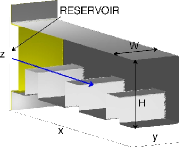
We next consider a second channel geometry, for comparison, and to illustrate the robustness of the mechanism. This is shown in Fig. 2a. The channel has height and width and side walls are now explicitly included. Only the bottom wall of the channel is patterned, by ridges of height and width 20 and spacing 40 which run all across its width. The aspect ratio of this channel, and the fact that only one wall is patterned, may make it more accessible experimentally.
Running simulations to locate the threshold value of the equilibrium contact angle gives a value of between and . A pinned configuration with is reported in Fig. 2b. (For a two dimensional geometry with no side walls . Thus, as expected, the hydrophilic side walls significantly increase ease of filling.)
Results of simulations for the grooved channel are shown in Fig. 2c. The simulation procedure was analogous to that used for the channel with posts, but with the contact angle cycling from at to at and back to at . The pattern of filling is very similar; as before the interface is halted at the first and third posts (compare Figs. 1c and Fig. 2c).
If the electrowetting potential is applied to the top wall only, the front is still depinned but touches the subsequent post before the bottom wall is completely wet. This leads to the formation of bubbles of air trapped between the posts. This could be avoided if necessary by choosing smaller ridges or more widely separated posts. An estimate of the geometry necessary to avoid bubble formation follows from observing that the advancing front makes an angle with the dry face of the ridge as it depins. Therefore to avoid the front touching the subsequent ridge without having completely wet the previous one, hence trapping a bubble, it is sufficient that the ratio of the height of the posts to the distance between them is less than . To check this we ran faster, two-dimensional simulations for the grooved geometry, similar to that reported in Fig. 2a but without lateral walls and with the electrowetting potential applied just to the top wall. Keeping the equilibrium contact angle on the patterned substrate fixed at 60∘, we switched the top wall between 60∘ and 25∘ reproducing a filling profile similar to that reported in Fig. 2c and with no air entrainment.
In this paper we have demonstrated that it is possible to use mesoscale simulations to study the behavior of an interface in a patterned microchannel. We have shown that surface patterning, together with electrowetting, can be used to control how the interface advances along the microchannel. We do not expect the valve mechanism to depend qualitatively on the size of the channel as long as the channel is sufficiently small that gravitational effects can be ignored. The obstacles must be at least a few microns in size, so that the fluid cannot overcome the pinning due to thermal fluctuations, and the advancing fluid must be non-volatile or it will move past the obstacles by evaporating and then condensing.
However there is a strong quantitative dependence of on the details of the patterning allowing this to be adjusted to lie between the available and . Moreover, although we have considered the quasistatic case, the threshold angle will increase for an interface with finite velocity or for pressure driven flow.
We hope that this paper will motivate experiments on patterned microchannels, and that simulations such as those presented here will be useful in determining suitable channel geometries for a given application and materials. Similar modelling approaches could also be used to predict when an interface depins from the end of a constriction in a microchannel or a micronozzle due to an applied pressure DGLSK-99 .
References
- (1) Y.-J. Cheng and L.-C. Hsiung, Biomed. Microdevices, 2004, 6, 341.
- (2) W. Satoh, H. Yokomaku, H. Hosono, N. Ohnishi, and H. Suzuki, J. Appl. Phys., 2008, 103, 034903.
- (3) K. Morimoto and H. Suzuki, Biosens. Bioelectron., 2006, 22, 86.
- (4) M. A. Burns, B. N. Johnson, S. N. Brahmasandra, K. Handique, J. R. Webster, M. Krishnan, T. S. Sammarco, P. M. Man, D. Jones, D. Heldsinger, C. H. Mastrangelo, and D. A. Burke, Science, 1998, 282, 484.
- (5) K. Hosokawa, T. Fujii, and I. Endo, Anal. Chem., 1999, 71, 4781.
- (6) D. C. Duffy, H. L. Gillis, J. Lin, N. F. Sheppard, and G. J. Kellog, Anal. Chem., 1999, 71, 4669.
- (7) C. Quilliet and B. Berge, Coll. and Int. Sci., 2001, 6, 34.
- (8) R. Lucas, Kolloid-Z, 1918, 23, 15; E. W. Washburn, Phys. Rev., 1921, 17, 273.
- (9) J. W. Gibbs, Scientific Papers 1906, Dover, New York, 1961; P. Concus and R. Finn, Acta Math., 1974, 132, 177.
- (10) B. M. Mognetti and J. M. Yeomans, Phys. Rev. E, 2009, 80, 056309.
- (11) J. W. Cahn, J. Chem. Phys., 1977, 66, 3667.
- (12) C. M. Pooley, H. Kusumaatmaja, and J. M. Yeomans, Eur. Phys. J. special topics, 2009, 171, 63; F. Diotallevi, L. Biferale, S. Chibbaro, G. Pontrelli, F. Toschi, and S. Succi, Eur. Phys. J. special topics, 2009, 171, 237.
- (13) S. Succi, The Lattice Boltzmann Equation, for Fluid Dynamics and Beyond, Oxford University Press, Oxford, 2001; J. M. Yeomans, Physica A, 2006, 369, 159.
- (14) M. R. Swift, E. Orlandini, W. R. Osborn, and J. M. Yeomans, Phys. Rev. E, 1996, 54, 5041; C. M. Pooley, H. Kusumaatmaja, and J. M. Yeomans, Phys. Rev. E, 2008, 78, 056709.
- (15) H. Kusumaatmaja, C. M. Pooley, S. Girardo, D. Pisignano, and J. M. Yeomans, Phys. Rev. E, 2008, 77, 067301.