Linear-optical implementations of the iSWAP and controlled NOT gates based on conventional detectors
Abstract
The majority of linear-optical nondestructive implementations of universal quantum gates are based on single-photon resolving detectors. We propose two implementations, which are nondestructive (i.e., destroying only ancilla states) and work with conventional detectors (i.e., those which do not resolve number of photons). Moreover, we analyze a recently proposed scheme of Wang et al. [J. Opt. Soc. Am. B 27, 27 (2010)] of an optical iSWAP gate based on two ancillae in Bell’s states, classical feedforward, and conventional detectors with the total probability of success equal to , where is detector’s efficiency. By observing that the iSWAP gate can be replaced by the controlled NOT (CNOT) gate with additional deterministic gates, we list various possible linear-optical implementations of the iSWAP gate: (i) assuming various ancilla states (unentangled, two-photon and multiphoton-entangled states) or no ancillae at all, (ii) with or without classical feedforward, (iii) destructive or nondestructive schemes, and (iv) using conventional or single-photon detectors. In particular, we show how the nondestructive iSWAP gate can be implemented with the success probability of assuming the same ancillae, classical feedforward, and fewer number of conventional detectors than those in the scheme of Wang et al. We discuss other schemes of the nondestructive universal gates using conventional detectors and entangled ancillae in a cluster state, Greenberger–Horne–Zeilinger and Bell’s states giving the success probability of , , and , respectively. In the latter scheme, we analyze how detector imperfections (dark counts in addition to finite efficiency and no photon-number resolution) and imperfect sources of ancilla states deteriorate the quantum gate operation.
OCIS numbers: 270.0270, 270.5585
I Introduction
In the last decade there has been much interest in probabilistic quantum computing using linear-optical elements and postselection based on counts at photodetectors (see a review Kok and references therein). These studies have been triggered by the pioneering works of Knill, Laflamme, and Milburn (KLM) Knill and Koashi, Yamamoto, and Imoto (KYI) Koashi . Various linear-optical implementations of universal two-qubit gates were proposed including the controlled NOT (CNOT) and controlled sign (CS) gates as listed in Table I.
Analysis of Table I shows that the majority of implementations of the CS/CNOT gates are based on selective (i.e., single-photon or photon-number resolving) detectors and thus achieving a higher probability of success in comparison to those schemes based on conventional detectors. However, in practical applications the most interesting implementations are those using conventional detectors (also referred to as the bucket detectors) which indicate the presence or absence of photons only.
Surprisingly, there are a very few schemes which are nondestructive and work with conventional detectors (see Table I). Apart from the proposal of Zou et al. Zou , there are schemes by Gasparoni et al. Gasparoni (scheme #14) and Zhao et al. Zhao (scheme #15), which are experimental realizations of the modified Pittman et al. gate Pittman (scheme #12) without feedforward. In these implementations a quantum encoder (described in Sect. IV) was used so that the whole setups could realize the nondestructive CNOT gate (with single-photon detectors). However, without having such photon-number resolving detectors for appropriate wavelength, they used conventional detectors in experiments. Moreover, two additional (conventional) detectors were added for postselection of the output states. So, they only realized a destructive version of the nondestructive CNOT gate of Pittman et al. Pittman .
In Sects. III and IV, we propose two implementations of the nondestructive universal gates based on conventional detectors.
In a recent article, Wang et al. Wang described a polarization-encoded linear-optical implementation of a nondestructive iSWAP gate using two entangled ancillae in the Einstein-Podolsky-Rosen (EPR) states, classical feedforward and conventional detectors. The total probability of success of this gate is , where is the detector efficiency and the power of corresponds to the number of simultaneously clicking detectors. In this article, we show how to simplify and improve the scheme of Wang et al. Wang to obtain the probability of success four times higher and to reduce the number of conventional detectors, while assuming the same ancillae.
The iSWAP, CNOT and CS are universal gates, so they are formally equivalent and each of them (together with single-qubit operations) can be used to construct any other gates and quantum circuits. Finding advantages of one universal gate over another can be understood only in terms of their experimental feasibility or specific qubit interactions in studied systems. For example, it is usually much easier to implement the iSWAP gates rather than the CNOT gates in solid-state systems. This is because the iSWAP operation naturally occurs during common solid-state qubit interactions described by the Heisenberg or XY models, while the CNOT operation can be generated from less common Ising interactions. For this reason, efficient quantum-information processing based on the iSWAP gates were studied for solid-state qubits Tanamoto . However, it seems that there is no clear advantage of the linear-optical implementations of the iSWAP gates over other universal optical gates, maybe except some realizations in specific hybrid optical and solid-state systems.
In Sect. II, we present simple schemes to decompose the iSWAP gate into the CS or CNOT gate, for which many proposals (see Table I and Appendix A) can be readily applied. In particular, by using such schemes together with an implementation of the CS gate by Zou et al. Zou , which was actually used in Ref. Wang , one obtains the iSWAP gate with the success probability . In Sect. III, we discuss other implementations of the iSWAP gate yielding and using as a resource the Gottesman-Chuang four-qubit entangled state Gottesman and a pair of Greenberger–Horne–Zeilinger (GHZ) states, respectively. In Sect. IV, we propose a scheme using the same resources (including ancillae in the EPR states) as the CS gate of Zou et al. Zou . We conclude in Sect. V.
| # | Authors | E/T | Comments | Feedforward | Entangled | Destructive | Conventional | |
| ancillae | detectors | |||||||
| I. UNENTANGLED ANCILLAE | ||||||||
| 1 | KLM Knill | T | no | no | no | |||
| 2 | Ralph et al. Ralph | T | simplified #1 | no | 0 | no | no | |
| 3 | Knill Knill2 | T | improved #1 | no | 0 | no | no | |
| 4 | Pittman et al. Pittman4 | E | no | yesa | no | |||
| 5 | ditto | T | modified #4 | yes | 0 | yesa | no | |
| 6 | Giorgi et al. Giorgi | T | modified #16 | yes | no | no | ||
| 7 | Bao et al. Bao | E | modified #13 | yes | no | no | ||
| II. ENTANGLED ANCILLAE | ||||||||
| 8 | KLM Knill | T | yes | EPR | no | no | ||
| 9 | KYI Koashi | T | yes | EPR | no | no | ||
| 10 | ditto | T | modified #9 | yes | EPR | no | no | |
| 11 | ditto | T | modified #9 | yes | EPR | no | no | |
| 12 | Pittman et al. Pittman | T | no | EPR | no | no | ||
| 13 | ditto | T | modified #12 | yes | EPR | no | no | |
| 14 | Gasparoni et al. Gasparoni | E | realization of #12 | no | EPR | yesa | yes | |
| 15 | Zhao et al. Zhao | E | realization of #12 | no | EPR | yesa | yes | |
| 16 | Giorgi et al. Giorgi | T | related to #12 | yes | EPR | no | no | |
| 17 | Zou et al. Zou | T | related to #12 | yes | EPR | no | yes | |
| 18 | Gottesman, Chuang Gottesman | T | — | yes | no | — | ||
| 19 | Pittman et al. Pittman | T | based on #18 | yes | no | no | ||
| III. WITHOUT ANCILLAE | ||||||||
| 20 | Pittman et al. Pittman | T | no | 0 | yes | no | ||
| 21 | ditto | T | modified #20 | yes | 0 | yes | no | |
| 22 | Pittman et al. Pittman2 | E | realization of #20 | no | 0 | yes | no | |
| 23 | Giorgi et al. Giorgi | T | related to #20 | no | yes | no | ||
| 24 | ditto | T | modified #23 | yes | 0 | yes | no | |
| 25 | Hofmann, Takeuchi Hofmann | T | no | yesa | no | |||
| 26 | Ralph et al. Ralph2 | T | equivalent to #25 | no | 0 | yesa | no | |
| 27 | O’Brien Obrien | E | realization of #25, #26 | no | 0 | yesa | no | |
| 28 | Okamoto et al. Okamoto | E | realization of #25, #26 | no | 0 | yesa | no | |
| 29 | Kiesel et al. Kiesel | E | simplified #25, #26 | no | yesa | no | ||
| 30 | Langford et al. Langford | E | equivalent to #29 | no | 0 | yesa | no | |
II Decomposition of the SWAP gate and improved scheme of Wang et al.
The iSWAP gate changes an arbitrary pure state of two photon-polarization qubits
| (1) |
into
where, e.g., and and represent horizontal and vertical polarization states, respectively. For the sake of simplicity, we refer here to qubits encoded in photon polarization only. Obviously, we can also refer to the photon-path and phase qubits which are dual-line qubits interchangeable with polarization qubits by a polarizing beam splitter and beam splitter, respectively Kok .
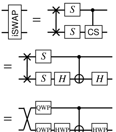
Schuch and Siewert Schuch showed that the CNOT gate can be decomposed into the two iSWAP gates or the SWAP and iSWAP gates. The latter relation was also applied in Ref. Wang but not in its full power. By inverting the Schuch-Siewert relation and replacing the CNOT by the CS gate, we find that the iSWAP gate can be simply given as (see the top circuit in Fig. 1)
| (2) |
in terms of the phase gate , the CS gate , and the SWAP gate. The scheme can also be given in terms of the CNOT gate, as shown in Fig. 1 (center), using the relation . The Hadamard gate can be implemented by the half-wave plate (HWP), which for a single qubit is given by:
| (3) |
tilted at .
The SWAP gate is a classical gate and can be implemented deterministically, e.g., by brute-force exchanging qubits or waveguides carrying single qubits. Using, the polarization-encoded qubits, the phase gate is simply implemented by a quarter-wave plate (QWP) with fast axis horizontal.
Note that, contrary to the iSWAP gate, the entangling power of the SWAP gate is zero, which means that this gate cannot entangle qubits, but it is just able to alter the configuration of existing entanglement among qubits. Sometimes this fact is confusing because the SWAP gate is said to have a capability of two ebits, where ebit is unit of bipartite entanglement. This is also correct in a communication scenario.
All gates except the CS (or CNOT) are deterministic, so the maximum success probability of the iSWAP is the same as for the CS and CNOT.
The scheme of the iSWAP gate due to Wang et al. Wang is based on proposals by Pittman et al. Pittman (scheme #12 in Table I) and Zou et al. Zou (scheme #17) implementing the CNOT/CS gates. Scheme #17 realizing the nondestructive CS gate offers (to our knowledge) the highest probability of success (equal to ) in this group of implementations using EPR states and conventional detectors as a resource.
Thus, by applying scheme #17 together with the decomposition scheme shown in Fig. 1, one obtains an implementation of the iSWAP gate yielding the probability of success , which is four times higher than that for the scheme of Wang et al. Wang . Moreover, the discussed scheme requires only eight conventional detectors instead of ten detectors used in Ref. Wang .
In the next sections, we present other CNOT and CS schemes, which can be used to implement the iSWAP gate with probability of success equal to , and .
III Scheme I with conventional detectors and ancillae in GHZ states
| 1 | 0 | 1 | 0 | |
| 0 | 1 | 0 | 1 | |
| 1 | 0 | 0 | 1 | |
| 0 | 1 | 1 | 0 |
| 1 | 0 | 1 | 0 | 1 | 0 | 1 | 0 | |
| 1 | 0 | 1 | 0 | 0 | 1 | 0 | 1 | |
| 0 | 1 | 0 | 1 | 1 | 0 | 1 | 0 | |
| 0 | 1 | 0 | 1 | 0 | 1 | 0 | 1 | |
| 1 | 0 | 0 | 1 | 1 | 0 | 1 | 0 | |
| 1 | 0 | 0 | 1 | 0 | 1 | 0 | 1 | |
| 0 | 1 | 1 | 0 | 1 | 0 | 1 | 0 | |
| 0 | 1 | 1 | 0 | 0 | 1 | 0 | 1 | |
| 1 | 0 | 0 | 1 | 1 | 0 | 0 | 1 | |
| 1 | 0 | 0 | 1 | 0 | 1 | 1 | 0 | |
| 0 | 1 | 1 | 0 | 1 | 0 | 0 | 1 | |
| 0 | 1 | 1 | 0 | 0 | 1 | 1 | 0 | |
| 1 | 0 | 1 | 0 | 1 | 0 | 0 | 1 | |
| 1 | 0 | 1 | 0 | 0 | 1 | 1 | 0 | |
| 0 | 1 | 0 | 1 | 1 | 0 | 0 | 1 | |
| 0 | 1 | 0 | 1 | 0 | 1 | 1 | 0 |
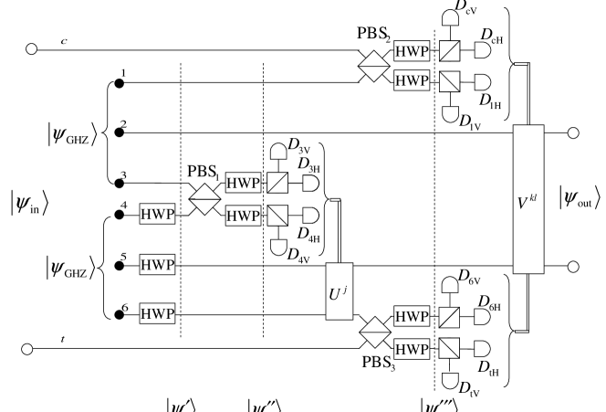
Here we describe an implementation (referred to as Scheme I) of the CNOT gate based on conventional detectors and ancillae prepared in the GHZ states as shown in Fig. 2. Scheme I is obtained by combining the schemes of Gottesman and Chuang Gottesman (scheme #18 in Table I) and Pittman et al. Pittman (scheme #19). It is worth stressing that scheme #19 was originally designed solely for selective detectors. Here, we show feasibility of the modified scheme #19 using conventional detectors. Moreover, the described scheme can be used as an implementation of the iSWAP gate according to Fig. 1.
Schemes #18 and #19 use ancilla in the following cluster-type state
| (4) |
which is equivalent (under local unitary transformations) to the standard four-qubit cluster states Raussendorf . In Eq. (4), and are Bell’s states (EPR states). Various schemes for generation of the state were proposed including a nondestructive scheme Wang2 yielding the probability of success equal to . It is possible to generate with the success probability using the Gottesman-Chuang protocol Gottesman , which we apply in the following.
Our detailed implementation of the CNOT gate, as shown in Fig. 2, is based on the schemes #18 and #19 and includes a scheme for generation of the state . An arbitrary input state , given by Eq. (1), is applied in modes (control) and (target). We use two ancillae in the GHZ states, , as a resource. Photons in modes , , and are sent through the Hadamard gate, which can be implemented by the HWP tilted at and is described by transformations and . For two photons with different polarizations, the Hadamard transformation reads as . Thus, the total input state (including the ancilla states) after the action of the Hadamard gates is changed into
| (5) | |||||
The state is sent through polarizing beam-splitter PBS1 in the -basis (i.e., which transmits -polarized states and reflects -polarized states) and the two Hadamard gates, which results in
where (=0,1) are given in terms of Pauli’s matrices , , and denotes no photon in and modes.
Whenever two photons reach separately detectors and or and , the state is generated at the output (see Table II). For combinations of single clicks at detectors and or and , the output state requires application of two Pauli’s gates on photons in modes and to obtain the state . The Pauli gate can be implemented by the HWP at according to Eq. (3).
Thus, in the discussed part of the scheme (shown in Fig. 2 up to operations), it is possible to generate the state after the successful postselection measurement and using feedforward. The probability of success of the generation of is equal to . The state is then used as an ancilla for the CNOT gate with the input state , given by Eq. (1).
The state after measuring modes 3 and 4 and passing through PBS2 and PBS3 in the -basis and four HWPs is transformed into
where for . The state is a superposition of states, which corresponds to a situation when two photons enter one pair of detectors, or for some (). On the contrary, successful events are those, when four photons are registered separately by all these pairs of detectors. Conventional detectors can be used because exactly four photons (without counting output photons) are always present in the setup. Other cases can be easily postselected without deteriorating the probability of success even for conventional detectors. Because of the application of Hadamard gates in front of polarizing beam-splitters, one can identify individual cases and use feedforward to correct the output states when it is necessary. After that one obtains , where as required by the CNOT operation for the input state given by Eq. (1).
The probability of success of the CNOT gate is equal to if the state is given. While the probability of success for the whole scheme shown in Fig. 2, including the generation of the state , accounts for
Finally, it is worth stressing that we treat the GHZ states as a resource. These states can be obtained from, e.g., EPR-state pairs by applying a nondestructive optical method as proposed by Zeilinger et al. Zeilinger . The first experimental generation of the GHZ state was realized by Bouwmeester et al. Bouwmeester . Since then various optical schemes for generation of the GHZ states were described (see, e.g., Refs. Fan ; Sagi ; Schafei ; Lu ) and, in principle, such methods can be used to generate ancillae for Scheme I.
IV Scheme II with conventional detectors and ancillae in EPR states
| 1 | 0 | 1 | 0 | |
| 0 | 1 | 0 | 1 | |
| 1 | 0 | 0 | 1 | |
| 0 | 1 | 1 | 0 |
| 1 | 0 | 1 | 0 | |
| 0 | 1 | 1 | 0 | |
| 1 | 0 | 0 | 1 | |
| 0 | 1 | 0 | 1 |
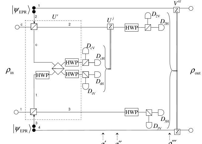
Here we describe an implementation of the CS gate, shown in Fig. 3 and referred to as Scheme II, using conventional detectors and ancillae in the EPR or EPR-like states. In our analysis of the experimentally-oriented Scheme II, we include a few kinds of detector imperfections (dark counts, finite efficiency, and no photon-number resolution) and realistic sources of the ancilla and input states.
Our Scheme II is a modified version of the proposals by Pittman et al. Pittman (scheme #12) and Zou et al. Zou (scheme #17). Note that scheme #17 was also applied by Wang et al. Wang as a part of their iSWAP scheme. The basic idea of Zou et al. was to use a quantum encoder to transform an input state into The probability of success for such device with feedforward mechanism is equal to (to compare with without feedforward). In both Refs. Zou and Wang two such encoders (with feedforward) were used to encode an input state and to obtain finally a nondestructive gate.
Scheme II is similar to scheme #17 since it is also based on the double use of the quantum encoder and the triple use of feedforward. However, the basic idea is different: In scheme #17, output states of the encoders are measured separately. In contrast, in our scheme the output states of the encoders are combined on a PBS and only then measured. So, using this part of Scheme II one can generate a cluster-like state, while two single-qubit quantum encoders in scheme #17 can give two separate EPR pairs. Moreover, contrary to Ref. Zou , we calculate gate fidelity assuming, in particular, dark counts and realistic sources of the EPR states.
In the case of the perfect CS gate, an arbitrary pure-state, given by Eq. (1), is transformed into Deviation of the output state of a realistic CS gate from the state of an ideal CS gate can be described by the fidelity defined by
| (6) |
Let us first analyze the action of the multigate composed of six gates marked in a dot-dashed box in Fig. 3:
| (7) |
where denotes the PBS unitary transformation of and lines. The PBS operation in the dual-line (dual-rail) notation (and assuming labelling of lines as shown Fig. 3) corresponds to swapping of -polarized modes and no action on -polarized modes. corresponds to the Hadamard gate, which can be equivalently implemented by a 50/50 beam splitter, when one of the input modes is -polarized and the other is -polarized, together with two phase shifters Kok . The latter implementation is particular useful to understand the Hadamard transformation applied to more than one photon.
For a moment, let us assume that the ancillae are in the perfect EPR states, . Thus, the total initial state is given by where is given by Eq. (1). The action of the multigate on the initial state can be compactly written as
| (8) |
where
with (=0,1), , and . In general, is of the form which, in a special case of all equal coefficients, reduces to a four-entangled cluster state . State corresponds to undesired cases, which can be excluded by measuring only modes and (the first postselection). In contrast, represents all the cases, in which more than one photon reaches a detector and so, by using conventional detectors, they cannot be distinguished from one-photon states. Thus, corresponds to undesired cases, which cannot be uniquely excluded via the first postselection, but can be later excluded after measuring modes and (the second postselection).
It is seen that, by assuming conventional detectors without dark counts and the ancillae to be in the perfect EPR states, one obtains the probability of success equal to and the fidelity equal to one as in the original scheme of Zou et al. Zou . Note that a successful measurement corresponds to clicks of four out of eight detectors (see Table III), which explains why . Moreover, factor 1/8 is just equal to in Eq. (8).
So far, we presented the transformations of states by assuming perfect sources of the ancilla states and no dark counts of detectors both for Schemes I and II. Here, in contrast, we use a numerical method assuming non-perfect sources of ancillae and input states, and dark counts.
For a conventional detector of efficiency and mean dark count rate , the positive-operator-valued measure (POVM) elements associated with distinguishing vacuum () and the presence of at least one photon () have the form:
| (9) |
where is given in terms of the dark count rate, , and the detector resolution time, Ozdemir .
We assume now that the entangled ancilla states are generated via spontaneous parametric down-conversion (SPDC). The output state of a type-II SPDC crystal or two type-I SPDC crystals sandwiched together can be approximated as an EPR-like state of the form (see, e.g., Refs. Gerry ; Gilchrist ):
| (10) |
where parameter is given by the product of interaction time of the pump field and the crystal, their coupling constant, and complex amplitude of the pump field. State, given by Eq. (10), clearly differs from the exact EPR state by inclusion of vacuum (and also higher order-states) in the superposition. Parameter is usually of the order /pulse Ozdemir and it describes the rate of single-photon pair generation per pulse of the pump field. Thus, the output state of the SPDC crystal contains vacuum with high probability and its effect on the gate operation cannot be neglected.
Each line in Schemes I and II can carry arbitrary number of photons in and polarizations. Using a dual-line notation, one can write and .
The state after the action of the multigate and the measurement of photons by the detectors , , , and is given by:
| (11) |
where , , is a renormalization constant, and the POVM elements are given by Eq. (9). Moreover, and are equal to 1 or 0, corresponding to clicks or no clicks of the detectors according to Table III.A. By applying the conditional gate with , defined in Table III.A, the state is transformed to . After the operation corresponding to the Hadamard gates at lines 2 and 3, and after photon counting by the detectors , , , and , the state is transformed to
| (12) |
where , while , and correspond to clicks or no clicks of the detectors according to Table III.B. Note that the PBSs in front of all the detectors just convert polarization qubits into dual-line qubits, so they are redundant if we apply the dual-line notation consistently in our numerical approach. The final output state is obtained from by applying the conditional gates () according to Table III.B.
For simplicity, in our numerical calculations we reserved three-dimensional Hilbert space for each mode, thus we set , , and and analogously for polarization. This is valid by assuming dark count rates and parameter to be relatively low. Otherwise, higher-dimensional Hilbert spaces should be set.
Let us assume realistic values of conventional detectors CPC1 (see also Refs. Ozdemir ; Miran ): the detector efficiency to be , the dark count rate , the detector resolution time =10 ns. For convenience, we assume that all detectors are the same. The rate of single-photon pair generation per pulse of the pump field is set to be /pulse Ozdemir . For experimental verification of Scheme II, it is useful to assume that the input state is also generated by the SPDC and is given by Eq. (10). For brevity, we analyze only the first cases in Table III, where no extra conditional operations are required. Under these assumptions, we find that the fidelity drops to , which is still relatively high.
V Conclusions
We studied linear-optical implementations of two-qubit universal gates including the iSWAP and CS/CNOT gates. As shown in Table I, the majority of these realizations of nondestructive gates are based on single-photon detectors. In contrast, we focused on practical implementations using conventional detectors, which do not resolve number of photons.
Despite of progress in constructing single-photon detectors (see Refs. JMO ; Takeuchi and references therein), they are still not commonly used. This conclusion can be drawn, e.g., by analyzing experimental realizations of quantum gates listed in Table I. One of the drawbacks of single-photon detectors is that their dark count rates are much higher than those for conventional detectors Takeuchi . There are also proposals of multiple-photon resolving detectors including cascade arrays of conventional detectors (connected with beam splitters or with high-speed low-loss optical switches Castelletto ) and fiber-loop detectors Rehacek . Such detectors, which are based on the idea of chopping up photons, are conceptually very attractive but still experimentally underdeveloped.
We analyzed a recent proposal of Wang et al. Wang to implement the iSWAP gate using two entangled ancillae in EPR states, classical feedforward, and conventional photodetectors (of a finite efficiency ) with the success probability of only. This scheme was based on an implementation of the CS gate by Zou et al. Zou (scheme #17 in Table I) with the success probability of .
We showed that the iSWAP gate can be decomposed into the CS/CNOT gate and deterministic gates including the SWAP, phase or Hadamard gates. Thus, one can immediately obtain schemes that implement the iSWAP gate by using the CS/CNOT gates with relatively high probability of success. In particular, by applying scheme #17 of Zou et al. Zou together with the iSWAP decomposition scheme, we showed how to implement the iSWAP gate with the success probability four times higher than that in the Wang et al. scheme.
Moreover, we studied applicability of conventional detectors to other implementations of nondestructive gates originally designed for single-photon detectors. We showed that the scheme of Pittman et al. Pittman implementing the nondestructive CNOT gate can be used also with conventional detectors achieving the probability of success equal to assuming as a resource the Gottesman-Chuang four-qubit entangled state Gottesman or equal to for a pair of ancillae in the GHZ states.
We have also described another scheme based on conventional detectors and ancillae in the EPR or EPR-like states as a modified version of the scheme by Zou et al. Zou . To verify experimental feasibility of this scheme, we showed how the quantum gate fidelity is deteriorated due to realistic sources of ancilla and input states, and detector imperfections to include dark counts, finite efficiency and no photon-number resolution.
Acknowledgements. The authors thank Nobuyuki Imoto, Bryan Jacobs, Masato Koashi, and Zhi Zhao for discussions. The work was supported by the Polish Ministry of Science and Higher Education under Grant No. 2619/B/H03/2010/38.
Appendix A Comparison of the schemes listed in Table I
Here, we give more explanations and compare various linear-optical implementations of the CS/CNOT gates listed in Table I. Obviously, these schemes can be used also to construct the iSWAP gate according to Fig. 1.
The implementations can be divided into several groups according to, e.g., different resources as shown in Table I: (I) unentangled ancillae, (II) entangled ancillae, and (III) without ancillae at all. Our examples of the second group include ancillae in the EPR states described in Sect. IV, but also the Gottesman-Chuang four-entangled state and the GHZ states discussed in Sect. III.
We compared the schemes concerning the total probability of success, destructive or nondestructive character of the implementations, application of conventional or nonconventional detectors, and whether the feedforward mechanism was applied. Classical feedforward means that a scheme includes measurement devices of some modes such that the classical outcomes of the measurements can be used to change the remaining modes.
In group I, where one or two ancillae prepared in an unentangled state were used, the highest probability of success for the gates without feedforward accounts for Knill2 (for scheme #3 in Table I). It is worth noting that there is only a numerical evidence Uskov , but not an analytical proof (contrary, e.g., the nonlinear sign shift gate Eisert ) that is the rigorous tight upper bound on the success probability using two unentangled ancillae without feedforward. Moreover, additional ancillae do not increase this value. When feedforward is used the probability can be increased to for gates with two ancillae Giorgi ; Bao (schemes #6 and #7) or even to with one ancilla Pittman4 (schemes #4 and #5) at the expense of destructing the output states. It should be mentioned that for all these groups of implementations, the destructive gates (i.e., those for which not only ancilla states are measured) achieve higher probabilities.
In group II, the best achieved probability of success accounts for without feedforward Koashi ; Pittman (schemes #9 and #12) and with feedforward Knill ; Pittman ; Giorgi (schemes #8, #13, and #16).
Group III consists of the CS/CNOT gates based on the idea of Hofmann and Takeuchi Hofmann (scheme #25), and Ralph et al. Ralph2 (scheme #26). Other examples in this group are mainly experimental realizations of the schemes #25 and #26 using a beam splitter with the reflection coefficient equal to . The probability of success for them achieves , assuming the measurement of both the control and target bits for postselection.
Intentionally, we have not included implementations of the CS/CNOT gates based on the idea of one-way computation using cluster states as proposed by Raussendorf and Briegel Raussendorf . According to their proposal one can implement the CS/CNOT gate by performing single-qubit measurement in an appropriate basis on a given cluster state. Using this procedure with additional feedforward it is possible to implement the CS/CNOT gate nearly deterministically even with conventional detectors as described, e.g., in Refs. Yoran ; Nielsen ; Browne ; Tokunaga and experimentally realized in Refs. Walther ; Kiesel2 ; Tokunaga2 ; Gao .
However, it should be stressed that such implementations of the CS/CNOT gates based on cluster-type states look deterministic only because it is assumed something strictly easier than applying the true CNOT gate on independently prepared input photonic qubits. The latter task should not be deterministic because of the no-go theorem for the Bell measurement by linear optics.
It worth clarifying that Table I includes two schemes using the cluster-type states. Namely, schemes of Gottesman and Chuang Gottesman (scheme #18) and closely related proposal of Pittman et al. Pittman (scheme #19) are implementations of the nondestructive and nondeterministic CNOT gate using a four-photon entangled state , which is equivalent, under a local unitary transformation, to a four-qubit cluster state. We included this gate in Table I since it does not realize the Raussendorf-Briegel protocol but uses the state as an ancilla only.
In Table I, we also have not included deterministic implementations of the universal gates based on single-photon cross-Kerr nonlinearities (see Refs. Nemoto ; Kok and references therein). Such schemes are fundamentally different from probabilistic linear-optical schemes. Moreover, there are serious doubts Shapiro whether they can be useful for quantum computing if applied for single photons in a standard way.
References
- (1) P. Kok, W. J. Munro, K. Nemoto, T. C. Ralph, J. P. Dowling, and G. J. Milburn, “Linear optical quantum computation with photonic qubits,” Rev. Mod. Phys. 79, 135-174 (2007).
- (2) E. Knill, R. Laflamme, and G. J. Milburn, “A scheme for efficient quantum computation with linear optics,” Nature (London) 409, 46-52 (2001).
- (3) M. Koashi, T. Yamamoto, and N. Imoto, “Probabilistic manipulation of entangled photons,” Phys. Rev. A63, 030301(R) (2001).
- (4) X. Zou, S. Zhang, K. Li and G. Guo, “Linear optical implementation of the two-qubit controlled phase gate with conventional photondetectors,” Phys. Rev. A75, 034302 (2007).
- (5) S. Gasparoni, J. W. Pan, P. Walther, T. Rudolph, and A. Zeilinger, “Realization of a photonic controlled-NOT gate sufficient for quantum computation,” Phys. Rev. Lett. 93, 020504 (2004).
- (6) Z. Zhao, A. N. Zhang, Y. A. Chen, H. Zhang, J. F. Du, T. Yang and J. W. Pan, “Experimental demonstration of a nondestructive controlled-NOT quantum gate for two independent photon qubits,” Phys. Rev. Lett. 94, 030501 (2005).
- (7) T. B. Pittman, B. C. Jacobs, and J. D. Franson,“Probabilistic quantum logic operations using polarizing beam splitters,” Phys. Rev. A64, 062311 (2001).
- (8) H. F. Wang, X. Q. Shao, Y. F. Zhao, S. Zhang, and K. H. Yeon, “Scheme for inplementnig linear optical quantum iSWAP gate with conventional detectors,” J. Opt. Soc. Am. B27, 27-31 (2010).
- (9) T. Tanamoto, K. Maruyama, Y.X. Liu, X. Hu, F. Nori, “Efficient purification protocols using iSWAP gates in solid-state qubits,” Phys. Rev. A78, 062313 (2008).
- (10) D. Gottesman and I. L. Chuang, “Demonstrating the viability of universal quantum computation using teleportation and single-qubit operations,” Nature (London) 402, 390-393 (1999).
- (11) N. Schuch and J. Siewert, “Natural two-qubit gate for quantum computation using XY interaction,” Phys. Rev. A67, 032301 (2003).
- (12) R. Raussendorf and H. J. Briegel, “A one-way quantum computer,” Phys. Rev. Lett. 86, 5188-5191 (2001).
- (13) H.F. Wang and S. Zhang, “Scheme for linear optical preparation of a type of four-photon entangled state with conventional photon detectors,” Eur. Phys. J. D 53, 359-363 (2009).
- (14) A. Zeilinger, M. A. Horne, H. Weinfurter, and M. Zukowski, “Three-particle entanglements from two entangled pairs,” Phys. Rev. Lett. 78, 3031-3034 (1997).
- (15) D. Bouwmeester, J.W. Pan, M. Daniell, H. Weinfurter, and A. Zeilinger, “Observation of three photon Greenberger-Horne-Zeilinger entanglement,” Phys. Rev. Lett. 82, 1345-1349 (1999).
- (16) X-F Fan, T. Yang, J. Li, C.F. Li, and G.C. Guo, “Generation three-particle entanglement states,” Phys. Lett. A 284, 59-62 (2001).
- (17) Y. Sagi, “Scheme for generating Greenberger-Horne-Zeilinger-type states of photons,” Phys. Rev. A68, 042320 (2003).
- (18) F. Shafiei, P. Srinivasan, and Z.Y. Ou, “Generation of three-photon entangled state by quantum interference between a coherent state and parametric down-conversion,” Phys. Rev. A70, 043803 (2004).
- (19) H-X. Lu, J. Zhang, X.-Q. Wang, Y-D. Li, and C-Y. Wang, “Experimental high-intensity three-photon entangled source,” Phys. Rev. A78, 033819 (2008).
- (20) S.K. Özdemir, A. Miranowicz, M. Koashi, and N. Imoto, “Quantum scissors device for optical state truncation: a proposal for practical realization,” Phys. Rev. A64, 063818 (2001).
- (21) A. Gilchrist, W.J. Munro, and A.G. White, “Input states for quantum gates,” Phys. Rev. A67, 040304(R) (2003).
- (22) C. Gerry and P. Knight, Introductory Quantum Optics (Cambridge University Press, 2004).
- (23) Data sheet on SPCM-AQ photon-counting module, EG&G, Optoelectronics Division, Vaudreuil, Canada.
- (24) A. Miranowicz, “Optical-state truncation and teleportation of qudits by conditional eight-port interferometry,” J. Opt. B 7, 142-150 (2005).
- (25) Special Issue on Single-Photon Detectors to J. Mod. Opt. 51, Issue 9, 1265-1557 (2004).
- (26) S. Takeuchi, J. Kim, Y. Yamamoto, and H.H. Hogue, “Development of a high-quantum-efficiency single-photon counting system,” Appl. Phys. Lett. 74, 1063-1065 (1999).
- (27) S. A. Castelletto, I. P. Degiovanni, V. Schettini, and A.L. Migdall, “Reduced deadtime and higher rate photon-counting detection using a multiplexed detector array,” J. Mod. Opt. 54, 337-352 (2007).
- (28) J. Řeháček and Z. Hradil, O. Haderka, J. Peřina, Jr., and M. Hamar, “Multiple-photon resolving fiber-loop detector,” Phys. Rev. A67, 061801(R) (2003).
- (29) E. Knill, “Quantum gates using linear optics and postselection,” Phys. Rev. A66, 052306 (2002).
- (30) D. B. Uskov, L. Kaplan, A. M. Smith, S. D. Huver, and J. P. Dowling, “Maximal success probabilities of linear-optical quantum gates,” Phys. Rev. A79, 042326 (2009).
- (31) J. Eisert, “Optimizing linear optics quantum gates,” Phys. Rev. Lett. 95, 040502 (2005).
- (32) G. L. Giorgi, F. de Pasquale and S. Paganelli, “Conditional sign flip via teleportation,” Phys. Rev. A70, 022319 (2004).
- (33) X. H. Bao, T. Y. Chen, Q. Zhang, J. Yang, H. Zhang, T. Yang and J. W. Pen, “Optical nondestructive controlled-NOT gate without using entangled photons,” Phys. Rev. Lett. 98, 170502 (2007).
- (34) T. B. Pittman, M. J. Fitch, B. C. Jacobs, and J. D. Franson, “Experimental controlled-NOT logic gate for single photons in the coincidence basis,” Phys. Rev. A68, 032316 (2003).
- (35) H. F. Hofmann and S. Takeuchi, “Quantum phase gate for photonic qubits using only beam splitters and postselection,” Phys. Rev. A66, 024308 (2002).
- (36) T. C. Ralph, N. K. Langford, T. B. Bell, and A. G. White, “Linear optical controlled-NOT gate in the coincidence basis,” Phys. Rev. A65, 062324 (2002).
- (37) M. A. Nielsen, “Optical quantum computation using cluster states,” Phys. Rev. Lett. 93, 040503 (2004).
- (38) D. E. Browne and T. Rudolph, “Resource-efficient linear optical quantum computation,” Phys. Rev. Lett. 95, 010501 (2005).
- (39) Y. Tokunaga, T. Yamamoto, M. Koashi, and N. Imoto, “Simple experimental scheme of preparing a four-photon entangled state for the teleportation-based realization of a linear optical controlled-NOT gate,” Phys. Rev. A71, 030301(R) (2005).
- (40) N. Yoran and B. Resnik, “Deterministic linear optics quantum computation with single photon qubits,” Phys. Rev. Lett. 91, 0379031 (2003).
- (41) P. Walther, K. J. Resch, T. Rudolph, E. Schenck, H. Weinfurter, V. Vedral, M. Aspelmeyer, and A. Zeilinger, “Experimental one-way quantum computing,” Nature (London) 434, 169-176 (2005).
- (42) N. Kiesel, Ch. Schmid, U. Weber, G. Tóth, O. Gühne, R. Ursin, and H. Weinfurter, “Experimental analysis of a four-qubit photon cluster state,” Phys. Rev. Lett. 95, 210502 (2005).
- (43) Y. Tokunaga, S. Kuwashiro, T. Yamamoto, M. Koashi, and N. Imoto, “Generation of high-fidelity four-photon cluster state and quantum-domain demonstration of one-way quantum computing,” Phys. Rev. Lett. 100, 210501 (2008).
- (44) W. B. Gao, P. Xu, X. C. Yao, O. Gühne, A. Cabello, C. Y. Lu, C. Z. Peng, Z. B. Chen, and J. W. Pan, “Experimental realization of a controlled-NOT gate with four-photon six-qubit cluster states,” Phys. Rev. Lett. 104, 020501 (2010).
- (45) K. Nemoto and W. J. Munro, “Nearly deterministic linear optical controlled-NOT gate,” Phys. Rev. Lett. 93, 250502 (2004).
- (46) J. H. Shapiro, “Single-photon Kerr nonlinearities do not help quantum computation,” Phys. Rev. A73, 062305 (2006).
- (47) T. C. Ralph, A. G. White, W. J. Munro, and G. J. Milburn, “Simple scheme for efficient linear optics quantum gates,” Phys. Rev. A65, 012314 (2001).
- (48) T. B. Pittman, B. C. Jacobs, and J. D. Franson, “Demonstration of nondeterministic quantum logic operations using linear optical elements,” Phys. Rev. Lett. 88, 257902 (2002).
- (49) J. L. O’Brien, G. J. Pryde, A. G. White, T. C. Ralph, and D. Branning, “Demonstration of an all-optical quantum controlled-NOT gate,” Nature (London) 426, 264-267 (2003).
- (50) R. Okamoto, H. F. Hofmann, S. Takeuchi, and K. Sasaki, “Demonstration of an optical quantum controlled-NOT gate without path interference,” Phys. Rev. Lett. 95, 210506 (2005).
- (51) N. Kiesel, Ch. Schmid, U. Weber, R. Ursin, and H. Weinfurter, “Linear optics controlled-phase gate made simple,” Phys. Rev. Lett. 95, 210505 (2005).
- (52) N. K. Langford, T. J. Weinhold, R. Prevedel, K. L. Resh, A. Gilchrist, J. L. O’Brien, G. J. Pryde, and A. G. White, “Demonstration of a simple entangling optical gate and its use in Bell-state analysis,” Phys. Rev. Lett. 95, 210504 (2005).