Electron-barrier interaction in a vacuum tunneling probe
Abstract
A model for dealing with energy and momentum exchanges between ballistic electrons and the vacuum barrier in a tunneling probe used as an electromechanical transducer is studied and its physical significance in devices of size comparable to the mean free path of the tunneling electrons is discussed.
The use of tunneling probes for scanning microscopy on surfaces is well known (see for instance ref. PLA1 ). More recently, use of tunneling probes to monitor displacements of macroscopic masses has been proposed as a high-sensitivity, low-noise electromechanical transducer to detect gravitational waves PLA2 . Further investigations on the device have shown that the back-action of the amplifier following the transducer is negligible and that the quantum limit comes earlier from the interaction process between the tunneling electrons and the barrier PLA3 . The application of the Heisenberg uncertainty principle to a vacuum tunneling probe has been the subject of two papers in which calculations in a second quantization PLA4 and in a first quantization framework PLA5 have been performed. The underlying physical hypothesis is the complete release of the momentum and energy of the tunneling electrons to the test mass. However, in the same papers PLA4 ; PLA5 a tunneling transducer is proposed to measure interatomic forces and to detect quantum noise. Due to the small size of the test mass in both these situations the total absorption of the tunneling electrons is not assured. When the sample has a size smaller than the mean free path for inelastic scattering the energy of the electrons is conserved or only partially released to the test mass, i.e. the electrons can move ballistically through the test mass. A partial conservation of the momentum of the electrons is also obtained with the diminishing of the number of elastic processes in a small travelled length. In this Letter we discuss a new definition of the momentum and energy transferred by the tunneling electrons to the test mass which is more adequate for dealing with such situations. Some consequences relevant for the proposed devices are finally stressed.
The vacuum gap between the test mass and a tip put close to its surface is schematized by a potential taken to be a one-dimensional barrier extending between points and (the tip is located at and the test mass at ). The force imparted by the tunneling electrons to the two sides of the barrier mat be decomposed in two contributions,
| (1) |
representing the forces inparted to the tip and to the test mass respectively. The decomposition procedure is explained in ref. PLA4 for two relevant shapes of , namely a piecewise constant or a linearly varying potential for . For instance, in the case of a square well barrier of height the two forces are the -distributions and . The force is relevant in calculating PLA4 ; PLA5 the momentum current transferred to the test mass by an electron in a tunneling eigenstate ,
| (2) |
where is the momentum current ,
| (3) |
evaluated inside the test mass (). Eq. 2 is obtained, under stationary conditions, from the continuity equation for the momentum flux which translates, in a quantum mechanical framework, the second law of dynamics
| (4) |
and by considering only the contribution to the force due to the test mass. Analogously, in the case of a first quantization approach use is made of the transferred momentum squared current
| (5) |
where is the momentum squared current ,
| (6) |
evaluated inside the test mass. As in the case of the momentum current eq. (5) is obtained, under stationary conditions, from the continuity equation for the momentum squared flux
| (7) |
In eq. (2) and (5) the momentum and momentum squared currents transferred to the test mass consist of two terms. The first one represents the momentum and momentum squared current, proportional to the energy, of the electrons moving inside the test mass. The second one is the contribution due to the quantum mechanical scattering at the interface between the vacuum and the test mass. Let us consider a model of interaction in which the transferred momentum and momentum squared currents are written, respectively as
| (8) |
| (9) |
The meaning of the new definition is quite clear: the exchange of energy and momentum is only related to the presence of the interface. This definition is appropriate to describe a ballistic propagation of the electrons inside the test mass (eq. (9)) with conservation of the longitudinal momentum (eq. (8)) along the direction from the tip to the test mass. In this situation we obtain, for and in the case of a rectangular barrier of height and width (the eigenstates are normalized with respect to the wavevector),
| (10) |
| (11) |
where and , being the electron energy and the transmission coefficient of the barrier. They must be compared with the analogous expressions obtained according to the definitions (2), (5),
| (12) |
| (13) |
We observe that, in the limit , and . On the other hand (12) and (13) do not have the same limit, this fact expressing an exchange of energy and momentum also in the absence of the barrier, namely a release of these quantities to the second electrode. For this reason we will call, in the following considerations, the first model corresponding to (8) and (9) the elastic model, the latter model corresponding to (2) and (5) the inelastic model.

The evaluation of the momentum uncertainty of the test mass due to incident electrons is obtained from the mementum and momentum squared currents PLA5 and in the elastic and inelastic models, respectively gives
| (14) |
and
| (15) |
Note that . The test mass shows also a position uncertainty . This arises from the uncertainty in the number of tunneling electrons through the dependence of the transmission coefficient on the width of the vacuum gap PLA5 ,
| (16) |
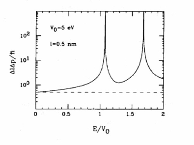
and it gives us finally the uncertainty products for both the elastic and inelastic models. These are shown in fig. 1 as a function of the energy of the incident electrons in the case of a rectangular barrier having eV and 0.5 nm. The graph also includes the tunneling for an electron energy greater than the barrier height, obtained by simply replacing in eqs. (14) and (15). The peaks in the curve of the elastic case are due to the divergence in the position uncertainty in the proximity of the zeros of the derivative of the transmission coefficient with respect to the displacement. By taking into account the second order expansion
| (17) |
the divergence disappears but in this case the transduction of the displacement is not linear. So one should avoid such conditions for a proper working of the device. We observe that these points are always in the regime of energy higher than the height of the barrier. Moreover, the divergences disappear considering, instead of an energy eigenstate for the tunneling electron, a more realistic wave packet.
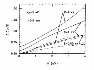
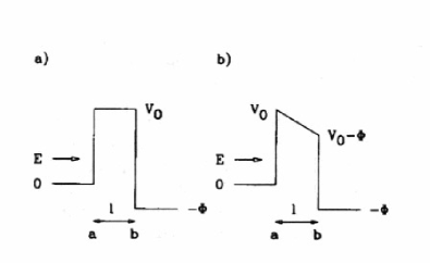
We have repeated the calculations of the uncertainty product for an asymmetrical rectangular barrier (fig. 2a) and a linearly slowing barrier (fig. 2b). Some results are shown, respectively, in figs. 3 and 4 as a function of the drop voltage across the barrier for different values of the incident energies. In both the cases the elastic model predicts higher sensitivity to the drop voltage with respect to the inelastic model.
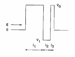
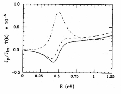
The situation corresponding to electron tunneling through a double barrier potential (fig. 5), was already studied in ref. PLA4 as a schematization of an atomic impurity near the surface of an electrode. In fig. 6 the momentum flux transferred to the test mass is shown versus the electron energy for both the elastic and inelastic models. The behaviour of the two curves is very similar and in both the cases the momentum flux goes from negative to positive values for increasing energy of the tunneling electrons crossing the zero for an energy roughly corresponding to the peak of maximum transmission. When the energy of the electron is small, the two curves are almost coincident.
To understand what the physical situations are in which the elastic model is more adequate to describe the electron barrier interaction we recall that both the proposed applications in refs. PLA4 ; PLA5 , because of the need for a momentum detection, are meaningful only if other sources of mechanical noise, like Brownian motion, are made negligible. This is obtained if the devices operate at very low temperature, of the order of 1-10 mK. In this case the electron-phonon coupling, proportional to the temperature, is negligible with respect to the electron-electron scattering. This last contribution has already been investigated in bulk metals and both models and measurements are in agreement with an increase of the mean free path of the electrons when their energy is below 20-30 eV, this last value depending upon the specific material. At low energy the behaviour of follows approximately the law PLA6
| (18) |
where and are empirically known. In the range which is of interest for tunneling of electrons, i.e. -1 eV, mean free paths of the order of are estimable. Another possibility is to consider the test mass to be a semiconductor crystal. In this case an electron mobility of 10 m2/V s can be achieved PLA7 which again gives a mean free path of for electrons of energy equal to 0.1 eV. In both the cases, despite the crude approximations, we have a mean free path of the same order, or more, of the size of the micromachined test masses to be used in the devices. In a very low energy regime we have shown that the results of the two models discussed here are almost identical. However, a range of energies in which tunneling happens and in which the two models give different predictions exists, according to the graphs in figs. 1, 3, 4 and 6. Therefore, we conclude that the elastic model has to be taken into account as a more adequate tool for the design of small-size, micromechanical devices based upon detection of momentum exchange in a tunneling probe.
Acknowledgements.
We thank F. Sacchetti for useful discussions and B.S. Waller for a critical reading of the manuscript.References
- (1) Proc. 4th Int. Conf. on Scanning Tunneling Microscopy/Spectroscopy, J. Vac. Sci. Technol. A 8 (1990) 153.
- (2) M. Niksch and G. Binning, J. Vac. Sci. Technol. A 6 (1988) 470.
- (3) M.F. Bocko, K.A. Stephenson and R.H. Koch, Phys. Rev. Lett. 61 (1988) 726; Phys. Rev. A 40 (1989) 6615.
- (4) B. Yurke and G.P. Kochansky, Phys. Rev. B 41 (1990) 8184.
- (5) C. Presilla, R. Onofrio and M.F. Bocko, Phys. Rev. B 45 (1992) 3735.
- (6) D.R. Penn, Phys. Rev. B 35 (1987) 482.
- (7) M. Heiblum, M.I. Nathan, D.C. Thomas and C.M. Knoedler Phys. Rev. Lett. 55 (1985) 2200.