Laser-like X-ray Sources Based on Optical Reflection from Relativistic Electron Mirror
Abstract
A novel scheme is proposed to generate uniform relativistic electron layers for coherent Thomson backscattering. A few-cycle laser pulse is used to produce the electron layer from an ultra-thin solid foil. The key element of the new scheme is an additional foil that reflects the drive laser pulse, but lets the electrons pass almost unperturbed. It is shown by analytic theory and by 2D-PIC simulation that the electrons, after interacting with both drive and reflected laser pulse, form a very uniform flyer freely cruising with high relativistic -factor exactly in drive laser direction (no transverse momentum). It backscatters probe light with a full Doppler shift factor of . The reflectivity and its decay due to layer expansion is discussed.
pacs:
41.75.Jv, 52.59.Ye, 52.38.PhHigh-quality X-ray sources are requested in many fields of science. Presently, large free-electron lasers (FEL) Ackermann2007 represent powerful coherent VUV and X-ray sources, which open a new era of intense VUV or X-ray interaction with matter and provide unprecedented opportunities for research in condensed matter physics, high-energy-density physics Lee2003 and single biomolecular imaging Neutze2000 . High laser harmonics from gas targets Seres2005 and relativistic laser plasma interaction Dromey2007 are also very useful and promising coherent X-ray sources. Such harmonic sources typically produce trains of sharp spikes separated by the time period of the driving laser pulse.
Bright and coherent X-ray sources can also be obtained by coherent Thomson scattering (CTS) from dense electron layers flying with relativistic factor . Here is the velocity of the plane flyer in normal direction. Counter-propagating probe light is then mirrored and frequency-upshifted by the relativistic Doppler factor, which is for Einstein1905 . In this paper we refer to these electron layers as relativistic electron mirrors (REM) or simply flyers. One way to produce them is to drive cold non-linear plasma waves to the point of wave breaking. Their density profile then develops diverging spikes that may move with high -factors Bulanov2003 . Recent experiments have demonstrated by identifying the mirrored light Pirozhkov2007 . This method is limited by the phase velocity of the plasma wave requiring low plasma density for high -factors of the wave. Higher densities can be achieved by accelerating thin solid foils. Corresponding simulations were reported recently Esirkepov2009 , driving a 250 nm thick foil with a laser intensity of about W/cm2. Only small values are obtained in this case, because the complete foil including ions is accelerated.
In this letter, a different regime is considered requiring much lower laser intensities and foils thin enough for the laser pulse to push out all electrons from the foil. In this case, only electrons are accelerated and can gain high values, while the heavy ions are left behind unmoved. For this to happen, the normalized laser field has to be much larger than the normalized field arising from charge separation, . Here is the circular frequency of the driving laser pulse, is the electron density and the thickness of the foil initially, while is the critical density. This regime has been described by Kulagin in a number of papers (see e.g.Kulagin ), and coherent Thomson scattering (CTS) from the emerging relativistic electron layers has been studied in Refs. CTS1 ; CTS2 . Some typical results are shown in Fig. 1. The scheme requires extremely thin foils of a few nanometer and laser pulses with a very high contrast ratio in order not to destroy the target before the main pulse arrives. These foils are much thinner than the skin depth and are therefore transparent, even though the electron density is overcritical. The leading edge of the laser pulse ionizes the foil and takes the electrons along as a thin sheath (see Fig. 1(a) and Fig. 2). Their motion is well described in a single-electron picture MtV2001 ; Wen2009 ; transverse and longitudinal momenta follow approximately the local laser vector potential according to , , where is now the full relativistic factor.
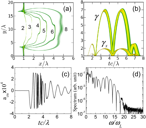
There are two severe drawbacks, when using these flyers as REMs for reflecting probe light. First, the flyer depends on time such that the reflected pulse is chirped and has a broad spectrum. Secondly, the mirror is much smaller than the full for (see Fig. 1(b)). In fact, we find for the Doppler shift
| (1) |
Apparently, the transverse momentum , inherent to electron motion in transverse light waves, degrades the upshift. This is true even though the angle of electron motion relative to the laser direction, , tends to vanish for large .
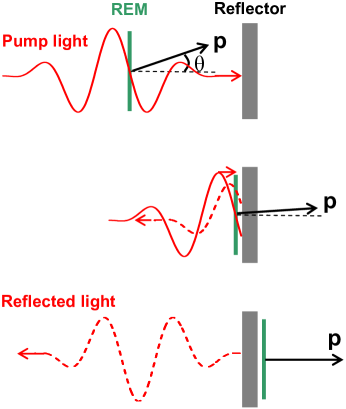
The major result reported in this Letter is a method to overcome these two drawbacks and to describe a practical way to generate flyers that have fixed values and . Accordingly, they can produce optical pulses that are Doppler-shifted by the full factor and have a narrow spectrum. They are only limited by decreasing reflectivity due to decay of the flyer. The way to suppress the transverse momentum is to let the electrons interact with a counter-propagating laser pulse. Here the central new observation is that reflection of the drive pulse from a perfect mirror provides the ideal interaction pulse. The corresponding configuration is sketched in Fig. 2. Due to relativistic kinematics, the reflected pulse changes the energy of the flyer electrons only marginally, but eliminates their transverse momentum completely. While the electrons gain energy when co-moving with the driving pulse for a long time, the interaction time with the reflected counter-propagating pulse is quite short, and, accordingly, the energy loss is only of order unity, ; this we have discussed in more detail in Ref. CTS1 .
Here we restrict ourselves to show explicitly only the elimination of . Let us denote electric and magnetic field of the plane drive pulse by (fields normalized to ). Reflection from a perfect mirror at , taking due account of a phase-shift , produces the reflected pulse . The electron transverse momentum obeys . It can be obtained as the sum of the momenta resulting from the interaction with drive and reflected pulse separately. These are described by
| (2a) | ||||
| (2b) |
Using new coordinates with in Eq. (2a) and with in Eq. (2b), one obtains the equations and , which are independent of the particular form of the electron trajectories and . Here we integrate the first one from , when the drive pulse first touches the electron, toward , when the electron hits the reflector. We also integrate the second one from , when the reflected wave front reaches the electron at time and location , toward . We find that the two momenta obtained from interaction with drive pulse and reflected pulse exactly cancel each other such that the electron emerging from behind the reflector foil has and therefore . Apparently, this result holds for each individual electron of the flyer independent of its initial distance from the reflector and the laser pulse shape . It is also independent of the charge separation field which eventually causes longitudinal dispersion of the mirror. The deeper reason for the cancelation of lies in the fact that, due to planar symmetry, the invariance still holds for the combined fields of forward-going and reflected pulse, and therefore since when passing the reflector Huang2010 .
We have checked these results by two-dimensional particle-in-cell (2D-PIC) simulations Wu2008 . Figure 1 exhibits electron expulsion from a thin foil and CTS of probe light from the emerging electron flyer for the case without reflector. Here the simulation box has a size of in plane, and a space resolution of cells and cells in x- and y- direction, respectively. The pump laser pulse has a profile with pulse duration . The carrier-envelope-phase of the laser is set to zero, so that the electric field maximum is at the pulse center. The transverse profile is chosen as a super-Gaussian with waist . We take , corresponding to an intensity of W/cm2 for nm.
Few-cycle pulses of this strength are presently becoming available Veisz . The laser pulse is linearly -polarized along the -direction and injected into the simulation box from the left boundary at . For this exploratory simulation, the initial ultrathin foil is chosen with density , thickness , and is located at . The initial plasma temperature is 10eV, and the ions are taken as immobile. The total number of macro-particles is about .
The electron density evolution is shown in Fig. 1(a). An electron layer is driven out of the foil (immobile ions at not shown), and one may notice some transverse electron motion in polarization () direction superimposed on the drift in laser () direction. Due to the transverse shaking, the effective area available for CTS is limited to the central zone between . The temporal evolution of and is shown in Fig. 1(b) for electrons located between . The energy spread of the electron layer increases with time and eventually leads to gradual longitudinal expansion. One also notices the conspicuous difference between and . The maximum values and agree with the single-electron prediction (see Eq.(1)). The evolution of follows approximately the laser vector potential according to the single-electron expression . After , the laser pulse has overtaken the electrons, which then return to rest in agreement with the Lawson-Woodward theorem LW1979 .
Signatures of probe light incident from the right side and backscattered from the relativistic electron layer are also shown in Fig. 1. In the simulation, the probe pulse is taken as a plane wave, , and -polarized (in -direction) to distinguish it from the drive pulse. A relatively small amplitude is chosen to make sure that the scattering is linear and that the flyer shape is not strongly perturbed. The reflected light is recorded by a fictitious observer located at . The temporal shape and spectrum of the reflected signal are shown in Fig. 1(c) and Fig. 1(d), respectively. By adjusting the time delay, we make sure that the fronts of both pump and probe pulse touch the production foil at the same time. The reflected signal therefore contains the whole information on the flyer dynamics. Since the Doppler shift varies with time, a complex oscillation pattern is observed in the reflected signal, leading to the broad spectrum seen in Fig. 1(d); the cut-off appears at in agreement with the peak values of . The two groups of rapid oscillations represent the two peaks in Fig. 1(b) and cause the spectral beating with period . Though interesting as a diagnostics of flyer dynamics, such CTS pulses are of little value as a light source.
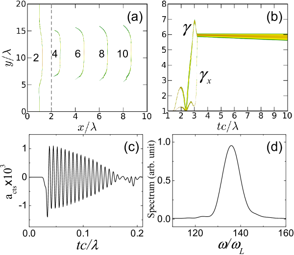
These results change drastically when adding the reflector foil. The configuration is illustrated in Fig. 2. Simulation results corresponding to those in Fig. 1, but now including the reflector, are depicted in Fig. 3. They highlight the central results of this Letter. It is observed that the electrons emerge from the reflector foil (marked by the dashed line in Fig. 3(a)) as a smooth dense layer in distinct contrast to the distorted shape seen in Fig. 1. In Fig. 3(b) one sees sharply rising and almost exactly merging with at a value of , while itself drops only by . This is due to the interaction with the reflected drive pulse. As predicted above on the basis of single-electron motion, interaction with the reflected pulse fully eliminates transverse electron momentum, while reducing electron energy only marginally.
Although these sudden changes occur close to the reflector foil, it is important to understand that they are not due to any direct action of the reflector foil on the electrons, but are mediated indirectly by the reflected laser field. The reflector foil is modeled here as a fully ionized plasma slab with a density of and a thickness of . This is sufficient to fully reflect the drive pulse. A reflectivity of is obtained in the simulation. On the other hand, the relativistic electron layer passes the thin reflector foil practically unperturbed. The relative energy loss due to Coulomb collisions is found to be negligible in the order of .
It appears that a uniform relativistic electron flyer with constant is produced that can now act as a CTS mirror. Backscattering of probe light by this mirror has been simulated, using the same parameters as for the results of Fig. 1, but now increasing space resolution in -direction to 1500 cells/ in order to resolve the CTS signal of much higher frequency and also enlarging the box length in -direction to . The reflected signal now consists of a regular wave train strongly compressed by the moving mirror (see Fig. 3(c)) and with a spectral peak (see Fig. 3(d)), Doppler-shifted by the factor in best agreement with . Here the observation point has been moved to to record the full CTS signal. Although the probe light is incident continuously, the CTS signal decays due to the expansion of the flyer clearly seen in Fig. 3(c). For an incident wavelength of nm, the X-ray pulse has a duration of about 500 attoseconds and a central wavelength of 5.7 nm. The maximum amplitude of corresponds to the intensity of W/cm2 and to a reflectivity of about . By slightly changing the parameters, we expect that a pulses of coherent X-ray photons are possible covering the range of the water window.
The coherent reflectivity of these electron flyers has been studied in Ref. CTS2 . For a flyer density distribution , given by a symmetric shape function with characteristic length , the CTS amplitude in normal direction can be obtained as
| (3) |
where is the Fourier transform
| (4) |
Here and denote the normalized x coordinate and layer thickness in the rest frame of the electron flyer; in the lab frame is given by . A similar form-factor appears in the theory of coherent synchrotron radiation Williams1989 . For a Gaussian profile , we find . Apparently, for such a shape the reflected signal vanishes exponentially as soon as , i.e. when the flyer becomes thicker than the wavelength of the reflected, . For the parameters studied above, we have , (Gaussian fitting), , and obtain in reasonable agreement with the PIC result shown in Fig. 3(c). The conversion ratio of pulse energy is found from Eq. (3) as
| (5) |
In conclusion, we have described a new method to make high-quality, micro-scale, relativistic electron mirrors. Dense electron layers, driven out from nanometer-thick production foils by few-cycle laser pulses, are significantly improved by introducing an additional reflector foil that reflects the drive laser pulse, but lets the electrons pass unperturbed. As a result, very uniform relativistic electron layers are obtained, freely cruising at fixed high- values precisely in drive-laser direction and with zero transverse momentum. Here we have discussed coherent Thomson backscattering from these layers to generate monochromatic, coherent, soft x-ray pulses, Doppler-shifted by a factor . The goal was to explain basic features in terms of single-electron dynamics and verifying the scheme by 2D-PIC simulation. The next step will be experimental demonstration. Though demanding, both the generation of the required high-contrast laser pulses and the fabrication of the micro-scale double foil targets should be within range in the next future. Successful demonstration would provide a new versatile tool for generating powerful laser-like X-ray pulses on a micro-scale.
Acknowledgements.
The authors are grateful to Dr. Lin Yin for useful discussions and comments and Dr. Chengkun Huang for a very helpful comment. J. Meyer-ter-Vehn acknowledges support by the Munich center for Advanced Photonics (MAP) and by the Association EURATOM - Max-Planck-Institute for Plasma Physics.References
- (1) W. Ackermann et al., Nat. Photonics. 1, 336 (2007).
- (2) R.W. Lee et al., J. Opt. Soc. Am. B 20, 770 (2003).
- (3) R. Neutze et al., Nature 406, 752 (2000).
- (4) J. Seres et al., Nature 433, 596 (2005).
- (5) B. Dromey et al., Phys. Rev. Lett. 99, 085001 (2007).
- (6) A. Einstein, Ann. Phys. (Leipzig) 17, 891 (1905).
- (7) S.V. Bulanov, T.Zh. Esirkepov, T. Tajima, Phys. Rev. Lett. 91, 085001 (2003).
- (8) A.S. Pirozhkov et al., Phys. Plasmas 14, 123106 (2007).
- (9) T.Zh. Esirkepov et al., Eur. Phys. J. D 55, 457 (2009).
- (10) V.V. Kulagin et al., Phys. Rev. Lett. 99, 124801 (2007).
- (11) J. Meyer-ter-Vehn and H.-C. Wu, Eur. Phys. J. D 55, 433 (2009).
- (12) H.-C. Wu and J. Meyer-ter-Vehn, Eur. Phys. J. D 55, 443 (2009).
- (13) J. Meyer-ter-Vehn, A. Pukhov, Z.-M. Sheng, Relativistic Laser Plasma Interaction, in Atoms, Solids and Plasmas in Super-Intense Laser Fields, edited by D. Batani et al (Kluwer Academic/Plenum Publishers, 2001).
- (14) M. Wen, J. Meyer-ter-Vehn, H.-C. Wu, B. Shen, Eur. Phys. J. D 55, 451 (2009).
- (15) Chengkun Huang, private communication (2010).
- (16) H.-C. Wu et al., Phys. Rev. E 77, 046405 (2008); ibid, New J. Phys. 10, 043001 (2008).
- (17) K. Schmid, L. Veisz, et al., Phys. Rev. Lett. 102, 124801 (2009).
- (18) P.M. Woodward, J. Inst. Electr. Eng. 93, 1554 (1947); J.D. Lawson, IEEE Trans. Nucl. Sci. 26, 4217 (1979).
- (19) G.P. Williams et al., Phys. Rev. Lett. 62, 261 (1989).