Observation of the growth of a magnetic vortex in the transition layer of a mildly relativistic oblique plasma shock
Abstract
A 2D particle simulation models the collision of two electron-ion plasma clouds along a quasi-parallel magnetic field. The collision speed is 0.9c and the density ratio 10. A current sheet forms at the front of the dense cloud, in which the electrons and the magnetic field reach energy equipartition with the ions. A structure composed of a solenoidal and a toroidal magnetic field grows in this sheet. It resembles that in the cross-section of the torus of a force-free spheromak, which may provide the coherent magnetic fields in gamma-ray burst (GRB) jets needed for their prompt emissions.
pacs:
52.35.Tc, 52.35.We, 52.65.RrThe ultrarelativistic jet of a Gamma Ray burst (GRB) gives rise to powerful eruptions of electromagnetic radiation, which can be detected across cosmological distances. The non-stationary plasma acceleration at the source of the GRB jet results in a nonuniform plasma density and flow speed within the jet. Plasma clouds will thus collide at a mildly relativistic speed, triggering the formation of radiative shocks at the boundaries between individual clouds. The ensemble of these shocks is, according to the internal shock model ReMes ; Piran , the source of the “prompt” GRB emissions.
Plasma processes and instabilities in the shock transition layer provide the relativistic electrons and the magnetic fields, which result in the emission of the electromagnetic radiation Filament ; Bret ; Schlickeiser . The filamentation instability and the formation of relativistic shocks has been widely investigated numerically with the help of particle-in-cell (PIC) simulations for electron-positron plasmas Kazimura ; Silva ; Jaroschek and for electron-ion plasmas Frederiksen ; Spitkovsky ; Martins , which were all initially unmagnetized. However, the magnetic fields driven by the filamentation instability in an initially unmagnetized plasma tend to have too short a lifetime , and too small a coherence length to explain the prompt GRB emissions Waxman .
The linear polarization of the GRB emissions suggests the presence of large-scale magnetic fields within the jets Lyutikov . This serves as a motivation to examine further with PIC simulations the shock formation and evolution in the presence of an ambient magnetic field. Flow-aligned Hededal and oblique Ohsawa ; Dieckmann ; Sironi guiding magnetic fields have been introduced in previous PIC simulations of electron-positron and electron-ion shocks. In particular the oblique electron-ion shocks are formidable amplifiers of the magnetic fields and accelerators of the electrons. However, the studies in the Refs. Ohsawa ; Dieckmann , that could be representative for a magnetized internal GRB shock, employed a one-dimensional simulation geometry, which suppresses the beam filamentation and, as we show here, the formation of current vortices.
A PIC simulation code solves the Maxwell’s equations and the relativistic Lorentz force equation for the computational particles Dawson . We perform here a two-dimensional simulation study with the widely used PSC code PSC . Figure 1 shows the simulation setup.
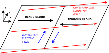
Two plasma clouds, each consisting of ions and electrons with the mass ratio , collide at the position . The initial electron and ion number densities of the dense cloud are both equal to and those of the tenuous cloud are both equal to . The velocity vectors of both clouds are antiparallel and aligned with . The modulus of each cloud in the box frame gives the collision speed . The dense cloud propagates to increasing values of . The temperature of all 4 plasma species is 131 keV, which yields an electron thermal speed , which is close to . The cloud density ratio and the collision speed are both compatible with the internal shock model Piran .
The plasma frequency of the ions of the dense cloud normalizes all quantities, which have the subscript for MKS units. The time , the position with , the velocity , the electric and magnetic fields and . The momenta are normalized as (ions) and (electrons). The initial gives a that equals the electron plasma frequency of the dense cloud. We obtain with . The modulus of the convection electric field is . The simulation box size is resolved by rectangular grid cells. The dense (tenuous) plasma is resolved by 100 (50) particles per cell per species. We employ periodic boundary conditions in all directions and no particles are introduced into the simulation after . The plasma clouds detach instantly from the boundary at and they will interpenetrate at . We will discuss in what follows the time evolution as shown in the movies followed by the plasma state at the simulation’s end at the time .
In the movies we show the whole time integrated evolution of the relevant parameters from to . Movie 1 shows the separate evolution of the field components . Movie 2 shows the evolution of in the upper panel and in the lower panel. In Movie 1 we see at early times the field is planar. The fields have a dipolar structure. As time elapses it becomes more and more nonplanar, filamented and fragmentary. The which is initially uniform assumes a fragmented morphology, with gradually increasing structural lengthscales. At early times the forming shock accelerates before reaching a steady speed. Striped magnetic fields - tell-tale signs of the filamentation instability in the and movies before . Gradually the magnetic fields become dominated by large-scale structures which represent the extrema. , a tracer of the plane current takes on the almost circular structure characteristic of the ring current. In Movie 2 we see the gradual breakup of the initial current sheet and the formation of a current ring. The sheet initially breaks up into smaller rings at which gradually increase in volume and merge () to form the final large rings, limited only by the box size. Incoming current filaments are deflected from the current sheet and shear off in the negative y direction, rolling up into vortex structures which later merge and distort the current sheet.
Figure 2 displays the phase space distributions of the electrons and of the ions, which have been integrated over all . The shows us the energies the electrons reach at the shock, while the merging of the ions of both clouds in is a necessary condition for a plasma shock.
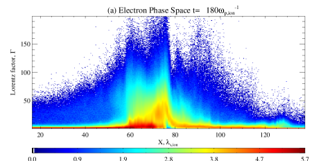
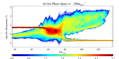
A downstream region is visible in for , which separates a reverse shock from the forward shock moving to increasing . The reverse shock is weaker than the forward one, due to the asymmetric plasma densities that yield a net flow of the downstream region. In what follows we discuss only the forward shock. Electrons reach in the cloud overlap layer values of in significant numbers and the fastest ones reach . An ion with the mass that moves with has in the simulation frame the kinetic energy of an electron with . A shock transition layer with reflects the incoming ions of the tenuous cloud and accelerates its electrons, as observed at the Earth’s perpendicular bow shock Anderson .
Figure 3 depicts , which has grown in amplitude by an order of magnitude compared to .

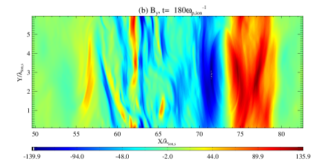

All magnetic components reveal elongated structures in the downstream region , which have a thickness of up to one ion skin depth. This magnetic field is tied to the current channels driven by the filamentation instability and the deflects the particles and thus the currents in all directions, causing them to form three-dimensional distributions. A massive coherent magnetic structure is present in the shock transition layer with . The and form a vortex, which rotates counterclockwise in the plane and is centered at , where its modulus . The vortex fills up the full -interval of the simulation box at this time. The has its peak at the center of the magnetic vortex and its amplitude decreases, radially from the centre .
The magnetic field shows a clear subdivision between its components in the simulation plane and the component orthogonal to it, which should hold also for the currents. Figure 4 shows the currents in and out of the simulation plane.
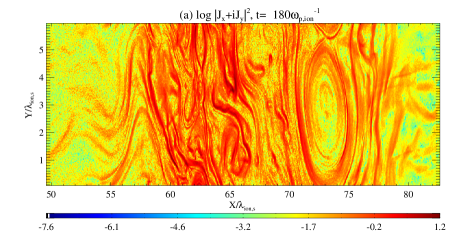
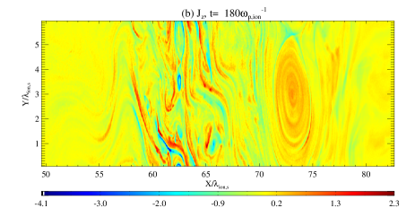
In agreement with the magnetic structure in Fig. 3, the currents in Fig. 4 are filamentary in the forming downstream region and in the interval , while they look fundamentally different in the shock transition layer in . Here and form a vortex centered at , while is strong in the ellipsoidal interval encircled by the vortex. Current channels almost parallel to are located within , which give rise to the quasi-planar at this position in Fig. 3(b). These current striations are what is left of the current sheet, which developed due to the different magnetic deflection of the upstream electrons and ions by the perpendicular magnetic field component of the shock.
Figures 3 and 4 reveal why the magnetic field structure in the shock transition layer appears to be stable. The current vortex in the plane is responsible for . This current is almost aligned with the magnetic field in the simulation plane in a region with , as Figs. 3(b) and 4(a) show. The current vortex thus experiences negligible magnetic force. Its sense of rotation is counter-clockwise and it gives an interior magnetic field that points in the positive -direction. The outside the current vortex is negligible and this system is analogous to an infinitely long coil with a symmetry axis parallel to . The current , which is responsible for the vortex formed by and , also flows along , because in the centre of the magnetic vortex. However, the magnetic field configuration is probably only approximately force-free, because the current vortex in Fig. 4(a) spirals into the interval with thereby coupling the current components. A force-free magnetic field must fullfill with a constant Old ; New , which is achieved here by the combination of a solenoidal component and of a ring component of with a comparable strength.
Discussion: Our simulation demonstrates the growth of the filamentation instability, in spite of the initial conditions that reduce its growth rate relative to the competing instabilities Dieckmann . The filamentation instability is, however, not the main source of the magnetic field within the shock transition layer. A current sheet develops at the front of the dense cloud, because the electrons and ions are not equally deflected by the perpendicular component of . This current sheet boosts the component of orthogonal to the flow direction to an amplitude , resulting in a magnetic energy density that is comparable to the initial ion kinetic energy density. This current sheet is unstable and a magnetic structure develops, which is composed of solenoidal and ring components. Such a topology can, in principle, be force-free. However, the current loop in the simulation plane is not closed and it is also elliptical. In fact, we cannot expect this magnetic field structure to be force-free. The ram pressure of the inflowing upstream plasma, the electron acceleration to extreme speeds and the ion reflection in the shock transition layer exert a force on this structure and they are probably responsible for its compression along into an ellipse. The spiral structure of the current in the simulation plane may be a remnant of the growth of the structure and thus a transient effect.
Clearly our simulation results are affected by the periodic boundary conditions in the direction and by the spatial 2D geometry. The 2D geometry assumes that the magnetic structure is an infinitely long cylinder with the symmetry axis along . A force-free 3D topology is obtained if the cylinder is bent to form a closed loop known as a spheromak, which is composed of poloidal and toroidal magnetic fields Old ; New . The structure we observe in our simulation would then be a cross-section of the torus. The obvious effect of the periodic boundary conditions along is to halt the growth of the magnetic structure, by which a steady state is reached (see the movies). This steady state is actually quite remarkable, considering the powerful particle acceleration processes taking place at this location. A wider interval will presumably result in a further growth of the magnetic structure. Spheromaks can be quite large and they have been invoked to explain large scale structures in the solar wind triggered by coronal mass ejections Kataoka . The poloidal magnetic field of the spheromak, which corresponds to in our simulation, is strong and homogeneous within the torus’ perimeter.
Our simulations suggest that spheromaks, or similar magnetic loops, that form within the current sheet of an internal GRB shock may thus provide the means to grow stable structures with a strong coherent magnetic field from kinetic scales to MHD scales. The current sheet, which is the source of this structure, does require an ambient magnetic field with a component orthogonal to the flow velocity vector and ions.
Acknowledgments: This work was supported by Science Foundation Ireland (SFI) grant number 08/RFP/PHY1694. Dr ME Dieckmann acknowledges support by Vetenskapsrådet. The SFI/HEA Irish Centre for High-End Computing (ICHEC) provided computational facilities and support.
References
- (1) M. J. Rees and P Meszaros, Astrophys. J. 430, L93 (1994).
- (2) T. Piran, Rev. Mod. Phys. 76, 1143 (2004).
- (3) M. V. Medvedev, and A. Loeb, Astrophys. J. 526, 697 (1999); J. J. Brainerd, Astrophys. J. 538, 628 (2000).
- (4) A. Bret, Astrophys. J. 699, 990 (2009).
- (5) R. Schlickeiser, and I. Lerche, Astron. Astrophys. 476, 1 (2007).
- (6) Y. Kazimura, J. I. Sakai, T. Neubert, and S. V. Bulanov, Astrophys. J. 498, L183 (1998).
- (7) L. O. Silva, R. A. Fonseca, J. W. Tonge, J. M. Dawson, W. B. Mori, and M. V. Medvedev, Astrophys. J. 596, L121 (2003).
- (8) C. H. Jaroschek, H. Lesch, and R. A. Treumann, Astrophys. J. 616, 1065 (2004).
- (9) J. T. Frederiksen, C. B. Hededal, T. Haugbolle, and A. Nordlund, Astrophys. J. 608, L13 (2004).
- (10) A. Spitkovsky, Astrophys. J. 673, L39 (2008).
- (11) S. F. Martins, R. A. Fonseca, L. O. Silva, and W. B. Mori, Astrophys. J. 695, L189 (2009).
- (12) E. Waxman, Plasma. Phys. Control. Fusion 48, B137 (2006).
- (13) M. Lyutikov, V. I. Pariev, and R. D. Blandford, Astrophys. J. 597, 998 (2003).
- (14) C. B. Hededal, and K. I. Nishikawa, Astrophys. J. 623, L89 (2005).
- (15) N. Bessho, and Y. Ohsawa, Phys. Plasmas 6, 3076 (1999).
- (16) M. E. Dieckmann, P. K. Shukla, and L. O. C. Drury, Astrophys. J. 675, 586 (2008).
- (17) L. Sironi, and A. Spitkovsky, Astrophys. J. 698, 1523 (2009).
- (18) J. M. Dawson, Rev. Mod. Phys. 55, 403 (1983).
- (19) M. Cerchez, R. Jung, J. Osterholz, T. Toncian, O. Willi, P. Mulser, and H. Ruhl, Phys. Rev. Lett. 100, 245001 (2008); P. Mulser, D. Bauer, and H. Ruhl, Phys. Rev. Lett. 101, 225002 (2008).
- (20) K. A. Anderson, R. P. Lin, F. Martel, C. S. Lin, G. K. Parks, and H. Rème, Geophys. Res. Lett. 6, 401 (1979).
- (21) S. Chandrasekhar, and P. C. Kendall, Astrophys. J. 126, 457 (1957); M. N. Rosenbluth, and M. N. Bussac, Nucl. Fusion 19, 489 (1979).
- (22) J. Cantarella, D. DeTurck, H. Gluck, and M. Teytel, Phys. Plasmas 7, 2766 (2000).
- (23) R. Kataoka, T. Ebisuzaki, K. Kusano, D. Shiota, S. Inoue, T. T. Yamamoto, and M Tokumaru, J. Geophys. Res. 114 A10102 (2009).