The ICC⋆ Algorithm: A fast way to include dielectric boundary effects into molecular dynamics simulations
Abstract
We employ a fast and accurate algorithm to treat dielectric interfaces within molecular dynamics simulations and demonstrate the importance of dielectric boundary forces (DBFs) in two systems of interests in soft-condensed matter science. We investigate a salt solution confined to a slit pore, and a model of a DNA fragment translocating thorugh a narrow pore.
keywords:
1 Introduction
Coarse-grained models are widely employed in computer simulations of soft-condensed matter systems because of the significant computational speed-up granted by the reduction in the number of degrees of freedom. A common coarse-graining approach is to employ an implicit solvent approach, thereby removing completely all solvent molecules. In the simplest scheme the polarizability of an aqueous solvent is taken into account by setting the dielectric constant to 80, thus reducing the electrostatic interaction by the same factor. This approach, however, fails in presence of interfaces between the solvent and materials of significantly different polarizability. Various methods to solve the Poisson equation with inhomogenous dielectric permittivity are available, and have been employed in different contexts, such as in Refs. [1, 2, 3, 4, 5, 6, 7, 8, 9, 10, 11]. One of the possibilities consists in solving the boundary integral equations using boundary element methods. This approach is particularly useful when the boundary integral problem is formulated in terms of an system of implicit linear equations which express the induced surface polarization charges in terms of the electric field[11, 12, 13, 14, 15, 16]. With the ICC⋆ algorithm[17] (Induced Charge Calculation with fast Coulomb Solvers) we enhanced the capabilities of different, widely employed electrostatic solvers with an iterative scheme to solve this set of equations. Noticeably, the procedure automatically yields solutions which obey the boundary conditions of the underlying Coulomb solvers, which is important to reduce the necessary system size.
In this article we review the algorithm and present two applications in the context of soft-condensed matter. The first one is the test case scenario of an electrolyte confined between two walls. In the second application we calculate the free energy barrier which a model DNA fragment has to overcome in order to be transported through a synthetic nanopore, for two different ionic strength conditions.
2 The ICC⋆ Algorithm
The goal of the ICC⋆algorithm is to solve the Poisson equation for an inhomogenous dielectric. The Poisson equation in cgs units reads as:
| (1) |
Let us suppose for simplicity that there is only one interface between the two regions 1 and 2 of different dielectric permittivities and . In order to express the boundary conditions in terms of induced surface charges, we integrate eq. 1 over a pillbox small enough that the inhomogenity of the electric field through its caps is negligible. Then the induced charge in the pillbox can be expressed as a surface integral
| (2) |
where is the surface normal, conventionally pointing from region 1 into region 2, and is the electric field in medium 1 or 2 in close proximity of the interface. The last equation is valid in the limit of a surface element of infinitesimal area .
The field at a given position on the surface can be written as a superposition of the field generated by the charged surface element in the very same location and of the field generated by other external and induced charges in the system. We denote the second contribution by and the charge density on the surface element by .
| (3) |
By combining Eqns.(2) and (3) one obtains an expression for the induced surface charge:
| (4) |
This boundary integral formulation can be implemented in a numerical boundary element scheme by assigning charge elements on a grid which discretizes the interface. Eq.(4) then is a set of coupled equations, which can be solved with different approaches. In the ICC⋆ implementation we decided to use a successive over-relaxation (SOR) scheme to solve them iteratively. When all boundary elements are approximated as point charges it is possible to determine with widely used fast Coulomb solvers that take into account the desired periodic boundary conditions of the system, and simultaneously determine the surface charge density to arbitrary precision. In every step of the iterative scheme the new guess for the charge at each surface element is determined from the previous value with the following equation:
| (5) |
where is obtained from Eq. (4). Here is a free parameter in the range between 0 and 2. With a value of we obtained a satisfactory speed of convergence and no stability issues in all performed simulations. Although more refined approximations than the use of point charges are available[10], our choice allowed us to readily implement the ICC⋆ algorithm in the ESPResSo molecular dynamics package. In ESPResSo it is currently possible to use ICC⋆ with the following electrostatic solvers: P3M[18, 19, 20], ELC[21, 22], MMM2D[23], and MMM1D[24, 25].
Finally it should be noted that in a typical coarse-grained simulation, the small change of particle positions in one simulation timestep leads only to a small change in the boundary element charge, so that each ICC⋆ update usually needs only 1-3 steps of the iterative algorithm.
3 Electrolyte in a Slit Geometry
As a first example of the use of ICC⋆ we report here the results of a coarse-grained Langevin dynamics simulation of a salt solution confined to a slit pore. We employ the restricted primitive model for electrolytes, namely representing ions as repulsive charged spheres embedded in a dielectric continuum with , and use the ICC⋆ algorithm to investigate the role of dielectric contrast between the solution and the wall material. The temperature was set to 300 K, and the Bjerrum length to 0.71 nm, corresponding to that of water at room temperature. An excluded volume interaction between ions was set up by means of a Weeks-Chandler-Anderson potential
| (6) |
with interaction strength equal to 1 ( being Boltzmann‘s constant) and a cutoff radius , where nm. The slit pore has a dimension of nm, with periodic boundary conditions applied along the two longer edges, and has been filled by 50 positive and 50 negative ions, reaching an approximate concentration of 200 mmol/l. In order to investigate the effect of the dielectric mismatch, the dielectric permittivity on the left wall of the pore has been set to 6400, while no dielectric contrast has been set for the solvent/right wall interface.
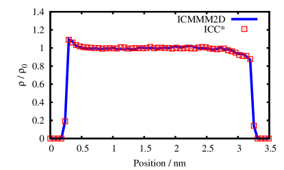
In Fig.1 we present a comparison between the density profile of ions in the slit, obtained with ICC⋆ in combination with MMM2D as an electrostatic solver, and with ICMMM2D. The latter method is an extension of the MMM2D algorithm, that takes into account the presence of dielectric mismatch for flat boundaries by means of image charges. As it is apparent from the results in Fig.1, the use of a discretization grid of elements for ICC⋆ is enough to obtain results compatible with the ones obtained by using ICMMM2D within a relative error of 1%. The target precision of MMM2D in both cases has been set to 0.1%. A depletion layer due to entropic reasons is observed at the right interface, where no dielectric contrast is present. The opposite phenomenon is observed at the left interface, where the presence of induced surface charges introduces an effective attractive force which compensates the entropic depletion layer and generates a local density increase.
4 Potential of Mean Force of a DNA segment in a Nanopore
Experiments on DNA translocation through biological and synthetic pores have recently attracted a lot of attention. Detailed descriptions of experiments are available e.g. in refs. [26, 27, 28, 29]. It has been shown that the translocation rate of DNA through a pore depends strongly on the ionic strength of the buffer, hence indicating an electrostatic contribution to the translocation free energy barrier. Since a highly charged object like DNA is repelled from walls that are less polarizable than water, we investigate to which extent the DBFs influence the translocation free energy barrier.
We modelled a synthetic nanopore using hard walls with a dielectric constant of 2, choosing the pore diameter and length to be 5 and 8 nm, respectively, as they fall within the range of experimental samples. On this length scale double stranded DNA (dsDNA) is stiff, as it has a persistence length of nm at physiological conditions. Therefore it is justified to model it as a series of beads (500, in this work) constrained on the pore axis. The inter-bead distance is kept fixed, and each of the beads bears a charge so that the linear charge density of 0.17/nm, characteristic of dsDNA, is reproduced.
Ions and counterions are represented explicitly. They interact mutually and with the DNA beads through a WCA potential having and nm, respectively, corresponding to a DNA diameter of 2 nm. The WCA interaction strength is set for both cases to 1 . The electrostatic interactions are calculated in full 3D periodicity with the P3M algorithm. We employ a cubic simulation box with a 20 nm long edge. To mimic the case of low salt concentration, only monovalent counterions were introduced in the box so that the DNA molecule is neutralized. In an additional simulation, a finite salt concentration of 100 mmol/l was added. All simulations were performed both with and without application of the ICC⋆ algorithm to investigate the influence of DBFs.
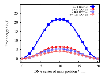
It is straightforward to calculate then the free energy barrier by computing the potential of mean force (PMF) acting on the center of mass of the model DNA along the pore axis. For this reaction coordinate the Fixman potential[30] is constant, and the PMF can be obtained by numerical integration of the mean force. The obtained PMFs are shown in Fig. 2. The free energy barrier in the salt-free case is strikingly higher (increasing to approximately ) when DBFs are taking into account using ICC⋆, in comparison to the case when DBFs are not considered. On the contrary, at a salt concentration of 100 mmol/l, the barrier increase is less pronounced, and the curves obtained with or without taking into account DBFs show a comparable pattern with a barrier height of about . The presence of a barrier for the higher salt concentration case, as well as in the case when no DBFs are considered, can be explained by the steric confinement of the counterion cloud in the nanopore. On the contrary, at low salt concentration the Coulomb interaction is not screened, and the effect of DBFs is maximized, leading to the observed higher free energy barrier.
5 Conclusion
We have presented the ICC⋆ algorithm and have shown that the presence of dielectric boundary forces in coarse-grained simulations cannot be neglected under many conditions. Polarization effects due to the presence of dielectric mismatches at interfaces can lead to important effects, as it has been demonstrated for the case of a salt solution confined to a slit pore, as well as in the case of the translocation free energy barrier of a model DNA through a nanopore. Although for the DNA-nanopore system screening at finite salt concentration reduces the influence of the dielectric boundary forces, in the case of a slit pore the effects cannot be neglected even at relatively high (200 mmol/l) concentrations.
We gratefully acknowledge financial support by the Volkswagen Foundation, by the Deutsche Forschung Gemeindschaft through SFB 716 - TP C5, and by the BMBF via the ScaFaCoS project. We thank the ESPResSo team for support.
References
- Warwicker and Watson [1982] J. Warwicker, H. Watson, J. Mol. Biol. 157 (1982) 671–9.
- Levitt [1978] D. Levitt, Biophys. J. 22 (1978) 209–219.
- Honig et al. [1993] B. Honig, K. Sharp, A. Yang, The Journal of Physical Chemistry 97 (1993) 1101–1109.
- Miertus et al. [1981] S. Miertus, E. Scrocco, J. Tomasi, Chem. Phys. 55 (1981) 117.
- Shaw [1985] P. B. Shaw, Phys. Rev. A 32 (1985) 2476–2487.
- Chipman [2004] D. Chipman, J. Chem. Phys. 120 (2004) 5566.
- Boda et al. [2004] D. Boda, D. Gillespie, W. Nonner, D. Henderson, B. Eisenberg, Phys. Rev. E 69 (2004) 046702.
- Allen et al. [2001] R. Allen, J. P. Hansen, S. Melchionna, Phys. Chem. Chem. Phys. 3 (2001) 4177–4186.
- Tomasi and Persico [1994] J. Tomasi, M. Persico, Chem. Rev. 94 (1994) 2027.
- Bardhan et al. [2009] J. Bardhan, R. Eisenberg, D. Gillespie, Phys. Rev. E 80 (2009) 11906.
- Lu et al. [2006] B. Lu, X. Cheng, J. Huang, J. A. McCammon, Proc. Natl. Acad. Sci. (USA) 103 (2006) 19314.
- Fenley et al. [1996] M. Fenley, W. Olson, K. Chua, A. Boschitsch, Journal of Computational Chemistry 17 (1996) 976–991.
- Zauhar and Varnek [1996] R. Zauhar, A. Varnek, J. Comp. Chem. 17 (1996) 864–877.
- Purisima [1998] E. Purisima, J. Comp. Chem. 19 (1998) 1494–1504.
- Bordner and Huber [2003] A. Bordner, G. Huber, J. Comput. Chem. 24 (2003) 353–367.
- Bharadwaj et al. [1995] R. Bharadwaj, A. Windemuth, S. Sridharan, B. Honig, A. Nicholls, J. Comput. Chem. 16 (1995) 898–913.
- Tyagi et al. [tted] S. Tyagi, M. Süzen, M. Sega, C. Holm, M. Barbosa, J. Chem. Phys. (submitted).
- Hockney and Eastwood [1981] R. W. Hockney, J. W. Eastwood, Computer Simulations using Particles, McGraw-Hill, New York, 1981.
- Deserno and Holm [1998a] M. Deserno, C. Holm, J. Chem. Phys. 109 (1998a) 7678.
- Deserno and Holm [1998b] M. Deserno, C. Holm, J. Chem. Phys. 109 (1998b) 7694.
- Arnold et al. [2002a] A. Arnold, J. de Joannis, C. Holm, J. Chem. Phys. 117 (2002a) 2496–2502.
- Arnold et al. [2002b] A. Arnold, J. de Joannis, C. Holm, J. Chem. Phys. 117 (2002b) 2503–2512.
- Arnold and Holm [2002] A. Arnold, C. Holm, Comput. Phys. Commun. 148 (2002) 327–348.
- Arnold and Holm [2005] A. Arnold, C. Holm, J. Chem. Phys. 123 (2005) 144103.
- Bródka [2006] A. Bródka, J. Chem. Phys. 125 (2006) 107103.
- Meller and Branton [2001] L. N. A. Meller, D. Branton, Phys. Rev. Lett. 86 (2001) 3435.
- Dekker [2007] C. Dekker, Nature Nanotech 2 (2007) 209–215.
- Howorka and Siwy [2009] S. Howorka, Z. Siwy, Chemical Society Reviews 38 (2009) 2360–2384.
- Storm et al. [2005] A. Storm, C. Storm, J. Chen, H. Zandbergen, J. Joanny, C. Dekker, Nano Lett. 5 (2005) 1193–1197.
- Fixman and Skolnick [1978] M. Fixman, J. Skolnick, Macromolecules 11 (1978) 863.