Quantum logical gates with four-level SQUIDs
coupled to a superconducting resonator
Xiao-Ling He1, Chui-Ping Yang2, Sheng Li3, Jun-Yan Luo1, and Siyuan Han41School of Science, Zhejiang University of Science and
Technology, Hangzhou, Zhejiang 310023, China
2Department of Physics, Hangzhou Normal University,
Hangzhou, Zhejiang 310036, China
3Department of Physics, Zhejiang Normal University,
Jinhua, Zhejiang 321004, China
4Department of Physics and Astronomy, University of
Kansas, Lawrence, Kansas 66045, USA
Abstract
We propose a way for realizing a two-qubit controlled phase gate
with superconducting quantum interference devices (SQUIDs) coupled
to a superconducting resonator. In this proposal, the two lowest
levels of each SQUID serve as the logical states and two
intermediate levels of each SQUID are used for the gate
realization. We show that neither adjustment of SQUID level
spacings during the gate operation nor uniformity in SQUID
parameters is required by this proposal. In addition, this
proposal does not require the adiabatic passage or a second-order
detuning and thus the gate is much faster.
pacs:
03.67.Lx, 42.50.Dv, 85.25.Dq
Introduction.—Superconducting devices including cooper
pair boxes, Josephson junctions, and superconducting quantum
interference devices (SQUIDs) have appeared to be among the most
promising candidates for scalable quantum computing, due to design
flexibility, large scale integration, and compatibility to
conventional electronics [1-3]. In the past few years, for SQUID
systems, many theoretical methods for realizing a single-qubit
gate and a two-qubit controlled-phase (CP) or controlled-NOT
(CNOT) gate have been presented [4-15].
For realizing a two-qubit CP gate with SQUIDs, several methods
have been proposed based on cavity QED technique [8-15]. These
methods are of importance in building quantum logic gates and open
a new avenue for the physical realization of quantum information
processing with SQUIDs in cavity QED. However, we note that these
methods have some disadvantages. For instances: (i) the methods
presented in [8,9] require adjustment of the level spacings of
SQUIDs during the gate operation, thus decoherence caused due to
the adjustment of level spacings may pose a severe problem; (ii)
the methods proposed in [10,11] require slowly changing the Rabi
frequencies to satisfy the adiabatic passage and the approaches
introduced in [12-14] require a second-order detuning to achieve
an off-resonant Raman coupling between two relevant levels; note
that when the adiabatic passage or a second-order detuning is
applied, the gate becomes slow (the gate time is on the order of
one microsecond to a few microseconds [11,13]); and (iii) the
proposal reported in [15] employs a two-mode resonator/cavity as
well as a second-order detuning between the two cavity modes;
technically speaking, the requirement for a SQUID interacting with
more than one cavity or resonator modes is difficult to meet. In
addition, it is noted that although two-qubit CNOT, CP, or iSWAP
gates have been experimentally demonstrated in superconducting
charge qubits, flux qubits, and phase qubits [16-18], to the best
of our knowledge, no experimental demonstration of a two-qubit
gate with SQUID qubits in cavity QED has been reported.
In this paper, we present an alternative method for implementing a
two-qubit CP gate with two SQUIDs coupled to a superconducting
resonator. As shown below, this proposal has the following
advantages: (a) there is no need for adjusting the level spacings
of SQUIDs during the gate operation, thus decoherence caused by
tuning the SQUID level spacings is avoided; (b) neither slowly
changing the Rabi frequency nor the use of second-order detuning
is required, thus the gate is significantly faster (as shown
below, the operation time of the gate is on the order of ten
nanoseconds); and (d) only one mode of the resonator is employed.
In addition, this proposal does not require identical coupling
constants of each SQUID with the resonator and thus is tolerable
to inevitable nonuniformity in device parameters. We believe that
this work is of interest because it avoids most of the problems
existing in the previous proposals.
Basic theory.—The SQUIDs considered throughout this paper are rf
SQUIDs each consisting of a Josephson tunnel junction enclosed by a
superconducting loop. The Hamiltonian for an rf SQUID, with junction capacitance and loop
inductance , can be written in the usual form [19]
(1)
where , the magnetic flux threading the ring, and , the total
charge on the capacitor, are the conjugate variables of the system, is the static (or quasistatic) external magnetic flux applied to
the ring, and is the Josephson coupling
energy, where is the critical current of the junction and is the flux quantum.
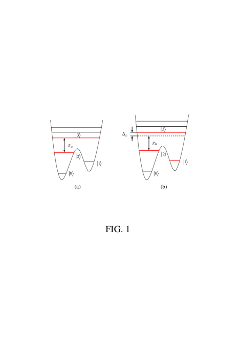
Figure 1: (a) SQUID-resonator resonant interaction. (b) SQUID-resonator
off-resonant interaction. The difference between the level spacings in (a)
and the level spacings in (b) can be achieved by choosing different device
parameters for SQUIDs.
A). SQUID-resonator resonant interaction. Consider a SQUID (say
SQUID ) coupled to a single-mode resonator and driven by a classical
microwave pulse. The SQUID is biased properly to have four lowest levels,
which are denoted by and respectively
[Fig. 1(a)]. The resonator mode is resonant with the transition but decoupled (highly
detuned) from the transition between any other two levels, which can be
readily achieved by adjusting level spacings of the SQUID [8,20]. In the
interaction picture, the interaction Hamiltonian for the SQUID and the
resonator mode, after making the rotating-wave approximation, can be written
as [8]
(2)
Here, the subscript represents SQUID and are the photon
creation and annihilation operators of the resonator mode with frequency ; is the coupling constant between the resonator mode and
the
transition of SQUID . The initial state and of
the system, under the Hamiltonian (2), evolve as follows
(3)
where and are the
vacuum state and the single-photon state of the resonator mode, respectively.
B). SQUID-resonator off resonant interaction. Consider a
system composed of a SQUID (say SQUID ) and a single-mode
resonator. Suppose that the resonator mode is off-resonant with
the
transition (i.e., ) while
decoupled from the transition between any other two levels of
SQUID [Fig. 1(b)]. Here, is the detuning between
the transition frequency of SQUID and the resonator mode frequency
and is the coupling constant between the
resonator mode and the transition. The effective interaction
Hamiltonian in the interaction picture can be written as [21,22]
(4)
where the subscript represents SQUID
From the Hamiltonian (4), it is straightforward to see that if the resonator
mode is initially in a single-photon state , the
time evolution of the states of the system is then given by
(5)
which introduces a phase shift to the state while to the state of the SQUID, when the resonator mode is in the state Note that the states and remain unchanged under the Hamiltonian (4).
In the following gate operations, we will need this resonant
interaction between the pulse and SQUIDs. Note that the resonant
interaction between the pulse and the SQUIDs can be completed
within a very short time, by increasing the pulse Rabi frequency
(i.e., by increasing the intensity/amplitude of the pulse).
Two-qubit CP gate.—Let us consider two SQUIDs and
By choosing different device parameters for each SQUID,
SQUIDs and can have the four-level configurations as
depicted in Fig. 1(a) and Fig. 1(b), respectively. The two logic
states of a SQUID qubit are represented by the two lowest levels
and while the
two intermediate levels and of each SQUID are utilized for the gate
realization. For the notation convenience, we here denote the
ground state (the first excited state) as level () for SQUID [Fig. 2(a′,b′,c′,d′,e′)]. We suppose that the resonator
mode is resonant with transition of SQUID while off-resonant with the transition of SQUID , which can be reached by prior adjustment of the level spacings of SQUIDs and . In addition, we assume that the resonator mode is initially in
the vacuum state The notations and involved in the
following gate operations are the transition frequency, the transition frequency, and the transition
frequency of SQUID ().
Figure 2: Illustration of SQUIDs interacting with the resonator mode and/or
the microwave pulses during the gate performance. The figures on the left
(right) side correspond to SQUID ().
The operations for realizing a two-qubit CP gate are listed as
follows:
Step (i): Apply a microwave pulse (with a frequency and a phase ) to SQUID for a time interval [Fig. 2(a)], to transform the state to Then,
wait for a time interval
during which the transition of SQUID resonantly interacts with
the resonator mode [Fig. 2(b)], to transform the state to as shown in Eq. (3).
It can be found that after this step, the following transformation is
obtained:
(6)
On the other hand, the state remains unchanged.
Step (ii): Apply a microwave pulse (with a frequency and a phase ) to SQUID
[Fig. 2(c)] while a microwave pulse (with a frequency and a phase ) to SQUID
[Fig. 2(b′)]. The Rabi frequency for the pulse
applied to SQUID is while the
Rabi frequency of the pulse applied to SQUID is . We set which can be achieved by adjusting the
intensities of the two pulses. After the pulse duration the state () of SQUID is transformed to the state () while the state of SQUID is transformed to the state .
Step (iii): Wait for a time Note that in the case when
the resonator mode is in the photon state the levels and of SQUID are not populated after the above
operations. Therefore, there is no coupling between the resonator
mode and SQUID . The resonator mode is off-resonant with the
transition of SQUID [Fig. 2(a′)]. It can be seen
from Eq. (5) that for the state changes to . On the other hand, the
state and remain unchanged.
Step (iv): Apply a microwave pulse (with a frequency and a phase ) to SQUID
[Fig. 2(c)] while a microwave pulse (with a frequency and a phase ) to SQUID
[Fig. 2(b′)]. Like step (ii), we set . After the pulse duration given in step
(ii), the state () of SQUID is transformed to the state () while the state of SQUID is transformed back to the state
.
Step (v): Perform an inverse operation of step (i) [Fig. 2(a,b)].
That is, wait for a time interval given in step
(i), during which the transition of SQUID resonantly
interacts with the resonator mode; and then apply a microwave
pulse (with a frequency and a phase ) to SQUID for a time interval given in step (i). It
can be verified that after this step, the following transformation is
achieved:
(7)
On the other hand, the state remains unchanged.
The states of the whole system after each step of the above operations are
summarized in the following table:
(24)
(33)
where is abbreviation of the state
of SQUIDs
() with . It can be concluded from Eq. (8)
that a two-qubit CP gate was achieved with two SQUIDs (i.e., the
control SQUID and the target SQUID ) after the above
process.
From the description above, it can be found that: (i) In contrast to the
previous proposals [8,9], the method presented above does not require
adjustment of the level spacings of the SQUIDs during the gate operation;
(ii) This method does not require slow variation of the Rabi frequency in
contrast to [10,11]; (iv) Compared with the previous approaches [12-14],
this method does not require a finite second-order detuning and thus the gate speed is improved by one order (here is the detuning of the pulse frequency with the transition
frequency between the two associated levels of SQUIDs; for the details, see
[12-14]); and (v) this method employs only one mode of the resonator, which
is different from the previous proposal [15].
Discussion.—Let us give a brief estimate on the gate time. As
shown above, the total operation time is
(34)
where is equal to (see steps (ii) and (iv)
above). Without loss of generality, let us consider s-1, which is available at present [9]. By choosing we have ns.
Several issues related to the gate operations above need to be addressed as
follows:
i) The level of SQUID is occupied in
steps (i) and (v). Since only SQUID-pulse resonant interaction and
SQUID-resonator resonant interaction are used in steps (i) and (v), the
operation time in step (i) or (v), equal to can be significantly
shorten by increasing the pulse Rabi frequency and the
coupling constant Alternatively, one can design the SQUID to have
a sufficiently long energy relaxation time for the level By doing these, we can have such that decoherence caused by the energy relaxation of
the level of SQUID is negligibly small.
ii) The occupation probability of the level for SQUID during step (iii) is given by [12]
(35)
which need to be negligibly small in order to reduce the gate error. For the
choice of , we have which can be further
reduced by increasing the ratio of
iii) For steps (i), (ii), (iv) and (v), the resonant interaction
between the resonator mode and the transition of SQUID involved during the
application of the pulse, is unwanted. To minimize the effect of this
unwanted interaction on the gate, the Rabi frequencies and require to be much larger than the coupling constant
i.e., Note that this condition can be
achieved by increasing and (i.e., via
increasing the pulse intensity).
iv) For either step (ii) or step (iv), when the SQUID is in the
state and the resonator mode is in the
single-photon state the unwanted off-resonant
interaction between the resonator mode and the transition of SQUID induces a
phase shift to the state
of SQUID , which will affect the desired gate performance. The effect of
this unwanted SQUID-resonator off-resonant interaction on the gate can be
made negligibly small as long as the condition is met. In the following, we will give a discussion on the effect of
this unwanted interaction on the fidelity of the gate.
Suppose that the two SQUID qubits are initially in a generic state described
by , where the coefficients satisfy the normalization. In the
ideal case, it can be seen from Eq. (10) that after the five-step operations
described above, the state
becomes On the other hand, when the effect of the
off-resonant interaction between the resonator mode and SQUID is
included during steps (ii) and (iv), one can easily work out the expression
for the final state after
performing the same operations above. To simplify our presentation, we will
not give a complete expression for due to its complexity.
The fidelity is given by
(36)
where
(37)
with and .
Eq. (11) shows that the fidelity is a function of . Thus, the average fidelity over all possible
two-qubit initial states is given by
(38)
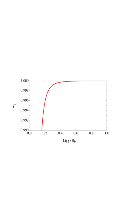
Figure 3: Average fidelity as a function of the Rabi frequency
(in unit of ) for .
It can be verified that when the unwanted “SQUID ”-resonator
off-resonant interaction in steps (ii) and (iv) is not considered (i.e., the
case for or ), we have and leading
to and We have plotted the average fidelity for the case (Fig. 3). One can see from Fig.
3 that the average fidelity increases as the Rabi frequency of the pulse applied to SQUID becomes larger, and the is when
Conclusion.—We have presented a way to realize a two-qubit
controlled phase gate with two SQUIDs, by the use of a microwave
superconducting resonator. As shown above, in this proposal, (a)
SQUIDs, which often have considerable parameter nonuniformity, can be used; (b) the adjustment of the level spacings, which is undesirable in
experiment, is avoided; and (c) neither the adiabatic passage nor a
second-order detuning is needed and thus the gate can be performed much
faster.
Acknowledgments.—S.H. was supported in part by the NSF Contract
No. DMR-0325551. S.L., J.Y.L and X.L.H. were supported in part by the
National Science Foundation of China under Grants 10904128 and 20804039.
C.P.Y acknowledges the funding support from the Hangzhou Normal University.
References
(1) Y. Yu, S. Han, X. Chu, S. I. Chu, and Z. Wang, Science 296, 889 (2002).
(2) I. Chiorescu et al., Nature (London) 431, 159 (2004).
(3) J. B. Majer et al., Phys. Rev. Lett. 94, 090501
(2005).
(4) M. H. S. Amin, A. Y. Smirnov, A. Maassen van den Brink, Phys.
Rev. B 67, 100508 (2003).
(5) C. P. Yang and S. Han, Phys. Lett. A 321, 273 (2004).
(6) Z. Kis and E. Paspalakis, Phys. Rev. B 69, 024510 (2004).
(7) C. P. Yang and S. Han, Phys. Rev. A 74, 044302 (2006).
(8) C. P. Yang, S. I. Chu, and S. Han, Phys. Rev. A 67, 042311
(2003).
(9) C. P. Yang and S. Han, Phys. Rev. A 72, 032311 (2005).
(10) K. H. Song, S. H. Xiang, Q. Liu, and D. H. Lu, Phys. Rev. A
75, 032347 (2007).
(11) P. Zhang, Z. D. Wang, J. D. Sun, and C. P. Sun, Phys. Rev. A
71, 042301 (2005).
(12) C. P. Yang, S. I. Chu, and S. Han, Phys. Rev. A 70,
044303 (2004).
(13) C. P. Yang, S. I. Chu, and S. Han, J. Phys.: Condens. Matter
16, 1907 (2004).
(14) K. H. Song, Z. W. Zhou, and G. C. Guo, Phys. Rev. A 71,
052310 (2005).
(15) K. H. Song, Chin. Phys. No.2 15, 286 (2006).
(16) T. Yamamoto et al., Nature (London) 425, 941 (2003).
(17) P. C. de Groot et al., Nature (London) 447, 836 (2007).
(18) R. C. Bialczak et al., arXiv:0910.1118.
(19) S. Han, R. Rouse, and J. E. Lukens, Phys. Rev. Lett.
76, 3404 (1996).
(20) S. Han, J. Lapointe, and J. E. Lukens, Single-Electron
Tunneling and Mesoscopic Devices (Springer-Verlag press, Berlin
Heidelberg, 1991) volume 31, 219–222.
(21) S. B. Zheng and G. C. Guo, Phys. Lett. A 223, 332 (1996).
(22) M. J. Holland, D. F. Walls and P. Zoller, Phys. Rev. Lett.
67, 1716 (1991).