High resolution Compton scattering as a Probe of the Fermi surface in the Iron-based superconductor LaO1-xFxFeAs
Abstract
We have carried out first principles all-electron calculations of the (001)-projected 2D electron momentum density and the directional Compton profiles along the [100], [001] and [110] directions in the Fe-based superconductor LaOFeAs within the framework of the local density approximation. We identify Fermi surface features in the 2D electron momentum density and the directional Compton profiles, and discuss issues related to the observation of these features via Compton scattering experiments.
pacs:
71.18.+y, 71.20.-b, 74.25.Jb 74.70.Dd1 Introduction
Since the discovery Kamihara of superconductivity in a family of iron-based superconductors (pnictides), there have been a large number of studies of their electronic properties that have revealed similarities between pnictides and cuprates. The theoretical prediction of a striped antiferromagnetic spin-density-wave (SDW) ground state Yildirim was confirmed by neutron scattering Clarina . Superconductivity is found in LaOFeAs with either hole doping Hai or electron doping Kamihara ; Chen . First principles calculations Boeri ; Singh1 find that the density of states (DOS) near the Fermi level () is predominantly due to Fe- orbitals. Owing to the approximate S4 symmetry of the FeAs tetrahedra, these Fe- orbitals split into lower lying eg (d,d) and higher lying t2g states (dxy,dyz,dzx)Chao ; Singh1 . Theoretical calculations Boeri ; Singh1 suggest that superconductivity may not be caused by electron-phonon coupling. Just as in the cuprates, the antiferromagnetic instability, which is suppressed by doping, is one candidate to explain unconventional superconductivity. Angle-resolved photoemission spectroscopy (ARPES) experiments have recently been carried out in BaFe2As2 Evtushinsky ; HDing , a related pnictide. The superconducting gap in LaFeAsO1-xFx with has been determined from the optical reflectance in the far-infrared region.Chen
X-ray scattering spectroscopy in the deeply inelastic (Compton) regime provides a direct probe of the correlated many-body ground state in bulk materials while avoiding the surface sensitivity of ARPES. The use of modern synchrotron sources cooper makes it possible to investigate complex materials via the measurement of directional Compton profilesLaukkanen .
In this paper, we report first-principles computations of the 2D-projected electron momentum density (2D-EMD) and Compton profiles (CPs) in the iron-based superconductor LaOFeAs. We discuss Fermi surface (FS) images in the 2D-EMD and its anisotropy defined by subtracting a smooth isotropic function from the spectrum. Our analysis of the CPs reveals that FS features related to hole- as well as electron-pockets are more prominent in the CP when the momentum transfer vector lies along the [100] rather than the [110] direction.
2 Methods
Our electronic structure calculations are based on the local density approximation (LDA) of density functional theory. An all-electron fully charge self-consistent semi-relativistic Korringa-Kohn-Rostoker (KKR) method is usedABkkr . The compound LaO1-xFxFeAs has a simple tetragonal structure (space-group P4/nmm). We used the experimental lattice parametersQiu2008 of LaO0.87F0.13FeAs in which no spin-density-wave order was observed in neutron-scattering. A non-spinpolarized calculation was performed and the magnetic structure was neglected. Self-consistency was obtained for =0 and the effects of doping were treated within a rigid band model by shifting the Fermi energy to accommodate the proper number of electrons. The convergence of the crystal potential was approximately Ry. The electron momentum density (EMD) was calculated on a momentum mesh with step (. The total number of points was within a sphere of radius 12.8 a.u. in momentum space. The 2D-EMD was calculated as
| (1) |
while the Compton profile is given by
| (2) |
3 Results and Discussions
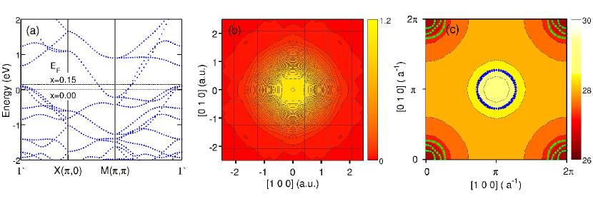
In Fig. 1(a), we show the LDA band structure of LaOFeAs. For =0, three bands cross the around the point, forming hole-like FSs [marked by green dots in (c)] while two bands cross around (,), forming electron-like FSs [marked by blue dots in (c)]. As electrons are added, the centered FSs shrink and completely disappear around =0.13. The bands near are dominated by the Fe orbitals. The FeAs layers are separated by insulating LaO layers, with the result that the dispersion of these bands along is small and, apart from a small -centered 3D hole pocket, the FSs are quasi two-dimensional. Based on the fully three-dimensional computations, we take advantage of this quasi two-dimensionality and investigate quantities in the plane by integrating out the component.
Figure 1(b) shows a map of the theoretical 2D-EMDmatsumoto2001 . This distribution can be described by an inverted bell shape with fourfold symmetry. The peak is at the zone center with tails extending over several unit cells. The dense contours around high symmetry points are signatures of the FS discontinuities. All these features are hidden behind the large inverted bell shaped signal. In order to investigate the Fermi surface topology in detail, we have employed both the 2D Lock-Crisp-West (LCW) foldinglcw1973 ; matsumoto2001 and the 2D-EMD anisotropy.
The 2D-LCW folding of the projected 2D-EMD is defined by
| (3) |
where gives the number of occupied states at the point in the first Brillouin zone by summing over all projected reciprocal lattice vectors . The effect of the matrix element can be eliminated via the 2D-LCW folding process of Eq. (3), which thus provides a tool for focusing on the FS features. The theoretical 2D-LCW folding shown in Fig. 1(c) has been smoothed using a Gaussian function with a.u., which is typical of the resolutions available in high resolution Compton scattering experiments. The positions and sizes of the FS pockets of the undoped parent compound LaOFeAs found by our KKR band calculation are shown as green dots for hole pockets and as blue dots for electron pockets. Before the application of the aforementioned Gaussian broadening, shows a maximum =29.4 and a minimum =24.5. The difference =4.9 is consistent with five bands crossing the Fermi level in the LDA calculation. Even after including experimental resolution, the FS features are still quite visible as seen in Fig. 1(c). The maximum of at is associated with the electron pockets; the minimum at (,) is related to the hole pockets.
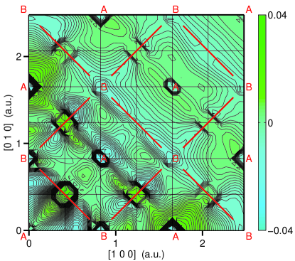
Figure 2 shows the 2D-EMD anisotropy, found by subtracting a smooth isotropic function from the 2D-EMD. FS features show up as closely spaced contours around (,) and (,) points. The momentum density around the points in the higher zones is seen to be lower (or higher) than the average due to the presence of hole pockets (or electron pockets). The zone-to-zone variation of intensity of these features can be understood as a matrix element effect associated with the symmetry of the hole pockets at and electron pockets at . For instance, the weak signal at the origin (,) can be understood since the bands crossing the Fermi level are predominantly orbitals, whereas only an orbital yields a significant contribution to the momentum density at the origin. Owing to interference effects, the FS features display a marked modulation from zone to zone. The Fe atoms in the unit cell are located at high symmetry positions, Fe1 (0,0,0) and Fe2 (0.5,0.5,0) (in units of lattice constants). The wavefunctions of these two Fe atoms show a constructive and destructive interference in momentum space, which can be represented by the structure factor , where is a reciprocal lattice vector. Whereas is largest when is even, vanishes when is odd. Therefore, the FS features show the alternating pattern seen in Fig. 2. For the FS hole-pockets centered at , the FS features at B for odd () are much weaker than those at A for even (). Deviations from this rule are an indication of hybridization of the Fe orbitals with other orbitals. For the FS electron-pockets centered at , a similar pattern is found. In Fig. 2 we show red lines crossing the B sites. The change of the momentum density along the direction in which is more rapid than changes along a direction for which .
The theoretical CPs along [100], [110] and [001] are shown in Fig. 3(a). The CP along [001] is a smooth curve, since there are no Fermi breaks along this direction. Thus, we can use this profile for highlighting FS features from the other profiles.
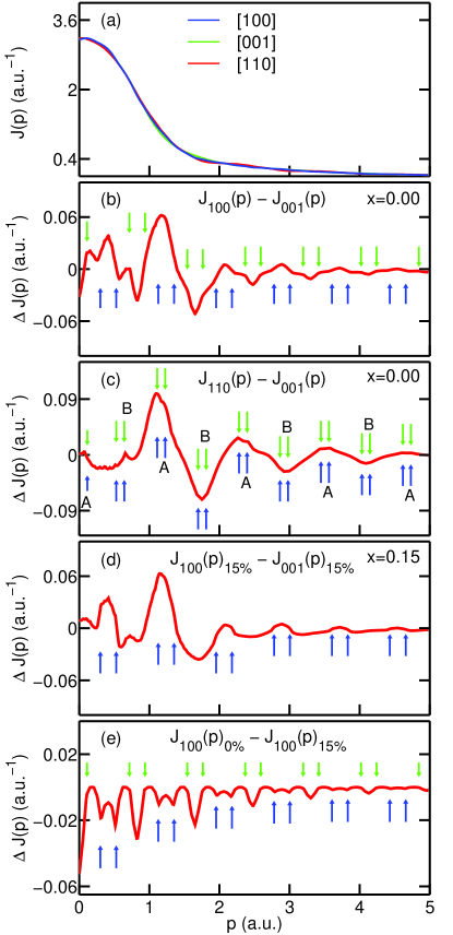
In Fig. 3(b), we subtract the [001] from the [100] CP. The resulting periodic patterns occur at the and points and are associated with hole pockets (green arrows) and electron pockets (blue arrows) respectively. The CP has a dip within the hole pocket regions and a hump within the electron pocket regions. The FS breaks are clearly visible and should be amenable to exploration via high resolution Compton scattering experiments with statistics high enough to numerically differentiate the difference profiles.
The same strategy is applied to the [110] CP in Fig. 3(c); however, the FS features are not as clear as in the [100] direction. The main reason is that the contributions of the hole- and electron-like FSs projected on [110] overlap each other and tend to cancel out. The interference pattern acts to amplify this effect as follows. When the EMD is projected to form the CP, the projections of A and B are distinct points along [110]. For hole pockets (centered at ), A (B) has strong (weak) signals associated with FS breaks. For electron pockets [centered at ], the red lines in the EMD are parallel to [110] at the projection of A, while they are perpendicular to [110] at the projection of B. We notice that the FS signals are strong only along the red lines. Therefore, at the projection of A (B), the FS signals are strong (weak) for both hole and electron pockets. In simple terms, at A, strong hole pocket signals cancel strong electron pocket signals, while at B weak hole pocket signals cancel weak electron pocket signals. Thus [110] is not a suitable direction for studying the Fermi breaks.
Next, we discuss how FS breaks disappear with electron doping. The Fermi level for =0.15 shown in Fig. 1(a) at 0.075eV is obtained by a rigid band shift. At this doping level, all hole pockets around are removed. As indicated by blue arrows in Fig. 3(d), the FS breaks associated with the FS electron pockets remain in the [100] CP. Compared to Fig. 3(b), the dips associated with the hole pockets have completely disappeared (green arrows). In Fig. 3(e), we subtract the [100] CP with % doping from the [100] CP with % doping. An interesting pattern of periodic maxima and minima appears around the and points which are identical with the positions of the hole and electron pockets, respectively. This may prove the most promising method of detecting FS signatures.
4 Conclusions
In conclusion, we have identified FS signatures in the momentum density of LaOFeAs, finding alternating intensity patterns in the 2D-EMD due to the symmetry of the crystal. FS signatures for both hole- and electron pockets are shown to be relatively strong in the [100] CP in comparison to the [110] CP. We thus conclude that the [100] direction is the favorable one for studying FS signatures. Our analysis further indicates that a doping-dependent experimental study should be able to determine at which doping level the hole-like FS’s disappear. The present work sets a baseline for future experimental Compton scattering studies in the pnictides.
5 Acknowledgments
This work is supported by the US Department of Energy, Office of Science, Basic Energy Sciences contract DE-FG02-07ER46352, and benefited from the allocation of supercomputer time at NERSC and Northeastern University’s Advanced Scientific Computation Center (ASCC). It was also sponsored by the Stichting Nationale Computer Faciliteiten (NCF) for the use of supercomputer facilities, with financial support from the Nederlandse Organisatie voor Wetenschappelijk Onderzoek (Netherlands Organization for Scientific Research).
References
- (1) Y. Kamihara, T. Watanabe, M. Hirano, and H. Hosono, J. Am. Chem. Soc. 130, 3296 (2008).
- (2) T. Yildirim, Phys. Rev. Lett. 101, 057010 (2008).
- (3) C. de la Cruz, Q. Huang, J.W. Lynn, J. Li, W. Ratcliff II, J.L. Zarestky, H.A. Mook, G.F. Chen, J.L. Luo, N.L. Wang and P. Dai, Nature 453, 899 (2008).
- (4) H.-H. Wen, G. Mu, L. Fang, H. Yang and X. Zhu, Europhys. Lett. 82, 17009 (2008).
- (5) G.F. Chen, Z. Li, G. Li, J. Zhou, D. Wu, J. Dong, W.Z. Hu, P. Zheng, Z.J. Chen, H.Q. Yuan, J. Singleton, J.L. Luo and N.L. Wang, Phys. Rev. Lett. 101, 057007 (2008).
- (6) L. Boeri, O.V. Dolgov, and A.A. Golubov, Phys. Rev. Lett. 101, 026403 (2008).
- (7) D.J. Singh and M.-H. Du, Phys. Rev. Lett. 100, 237003 (2008).
- (8) C. Cao, P.J. Hirschfeld and H.-P. Cheng, Phys. Rev. B 77, 220506 (2008).
- (9) D.V. Evtushinsky, D.S. Inosov, V.B. Zabolotnyy, A.Koitzsch, M. Knupfer, B. Büchner, Viazovska, M.S., G.L. Sun, V. Hinkov, A.V. Boris, C.T. Lin, B. Keimer, A. Varykhalov, A.A. Kordyuk and S.V. Borisenko, Phys. Rev. B 79, 054517 (2009)
- (10) H. Ding, P. Richard, K. Nakayama, K. Sugawara, T. Arakane, Y. Sekiba, A. Takayama, S. Souma, T. Sato, T. Takahashi, Z. Wang, X. Dai, Z. Fang, G.F. Chen, J.L. Luo and N. L. Wang, Europhysics Letters 83, 47001 (2008).
- (11) M.J. Cooper, P.E. Mijnarends, N. Shiotani, N. Sakai and A. Bansil (editors), X-Ray Compton Scattering, Oxford University Press (2004).
- (12) J. Laukkanen, K. Hämäläinen, S. Manninen, A. Shukla, T. Takahashi, K. Yamada, B. Barbiellini, S. Kaprzyk and A. Bansil, J. Phys. Chem. Solids 62, 2249 (2001). (2004).
- (13) A. Bansil, S. Kaprzyk, P.E. Mijnarends and J. Toboła, Phys. Rev. B 60, 13396 (1999).
- (14) Y. Qiu, M. Kofu, W. Bao, S.-H. Lee, Q. Huang, T. Yildirim, J.R.D. Copley, J.W. Lynn, T. Wu, G. Wu, and X.H. Chen, Phys. Rev. B 78, 052508 (2008).
- (15) I. Matsumoto, J. Kwiatkowska, F. Maniawski, M. Itou, H. Kawata, N. Shiotani, S. Kaprzyk, P.E. Mijnarends, B. Barbiellini and A. Bansil, Phys. Rev. B 64, 045121 (2001).
- (16) D.G. Lock, V.H.C. Crisp, and R.N. West, J. Phys. F: Met. Phys. 3, 561 (1973).