Leakage radiation microscopy of surface plasmon polaritons
Abstract
We review the principle and methodology of leakage radiation microscopy (LRM) applied to surface plasmon polaritons (SPPs). Therefore we first analyse in detail the electromagnetic theory of leaky SPP waves. We show that LRM is a versatile optical far-field method allowing direct quantitative imaging and analysis of SPP propagation on thin metal films. We illustrate the LRM potentiality by analyzing the propagation of SPP waves interacting with several two dimensional plasmonic devices realized and studied in the recent years.
I Introduction
In recent years intensive investigations of surface plasmon
polaritons (SPPs) have been made in the promising context of
nanophotonics. This research is actually motivated by the
current trends for optical device miniaturisation and by the
possibilities of merging aspects of nanophotonics with those of
electronics. SPPs are electromagnetic waves bounded to
dielectric-metal interface. As surface waves, SPPs are
exponentially damped in the directions perpendicular to the
interface Raether . Furthermore, SPPs could be used to
transfer optical information in a two dimensional (2D) environment.
This appealing property can be used for optical addressing of
different 2D optical systems and nanostructures located at a
dielectric/metal interface. Actually several 2D SPP devices
including passive nanostructures including mirrors or beam splitter
and active elements like molecules or quantum dots are currently
under development and investigation. Developments such as these
raise the prospect of a new branch of photonics using SPPs, for
which the term ”plasmonics” emerged Barnes:2003 ; Ebbesen:2007 ; Drezet:Micron .
However, for experimental investigations of optical devices an
important characteristic of SPP modes is that their spatial
extent is governed and defined by the geometry of the nanoelements
rather that by the optical wavelength Krenn:1999 . This
consequently opens possibilities for breaking the diffraction
limit but requires instruments of observation adapted essentially
to the subwalength regime and being capable of imaging the
propagation of SPPs in their 2D environment. Usually the analysis of
the subwalength regime implies necessarily near field optical (NFO)
methods Pohl ; Courjon:2003 able to collect the evanescent (i. e., non
radiative) components of the electromagnetic fields associated
with SPPs. However, when the metal film on which the 2D optical
elements are built is thin enough (i. e ., with a thickness below
80-100 nm) and when the subtratum optical constant (usually glass)
is higher than the one of the superstratum medium an other
possibility for analyzing SPP propagation occurs. This possibility
is based on the detection of coherent leaking of SPPs through the
substratum. Such a far-field optical method is called leakage
radiation microscopy (LRM) Hecht ; Bouhelier ; Stepanov and allows indeed a direct quantitative
imaging and analysis of SPP propagation on thin metal films.
The aim of this article is to present a short overview of recent
progress in the field of SPP imaging using LRM. In a first part of
this work we will describe the theoretical principles underlying
LRM. In the second part we will discuss modern leakage radiation
methods and illustrate the LRM potentialities by analyzing few
experiments with SPP waves interacting with 2D plasmonic devices.
II Leakage radiation and surface plasmon polaritons
In order to describe the theoretical mechanisms explaining leakage radiation it will be sufficient for the present purpose to limit our analysis to the case of a metal film of complex permittivity ( is the pulsation) sandwiched between two dielectric media of permittivity (substrate) and (superstratum). This system is theoretically simple and to a good extent experimentally accessible Raether ; Burke . In the limiting case where the film thickness is much bigger than the SPP penetration length in the metal (i. e., nm for gold or silver in the visible domain) one can treat the problem as two uncoupled single interfaces. We will consider as an example the interface 0/1 (the media 0 and 1 are located in the domain and respectively ). Such an interface will be identified in the following with the plane in cartesian coordinates. An elementary harmonic SPP wave is actually a TM electromagnetic mode characterized by its pulsation and its magnetic field where the y component can be written
| in the medium 0 | |||||
| in the medium 1, | (1) |
and where is the (complex valued) wavevector of the SPP propagating in the x direction along the interface. are the wave vectors in the medium j =[0 (dielectric), 1 (metal)] along the direction normal to the interface. By applying boundary conditions to Maxwell’s equations one deduces additionally and
| (2) |
which implies
| (3) |
| (4) |
for a SPP wave propagating along the x direction. The choice of the sign convention connecting the z and x components of the wave vector is a priori arbitrary and must be done only on a physical ground.
Indeed, due to ohmic losses in the metal we expect an exponentially decaying SPP wave propagating along the interface. This condition implies the relation Burke . This inequality is actually always fulfilled since from Eq. 3 one deduces
| (5) |
which is indeed positive because . By writing one additionally obtains the relation
| (6) |
This relation fixes the sign conventions since the wave must also decay exponentially when going away from the interface in both media. More precisely one gets
| (7) |
| (8) |
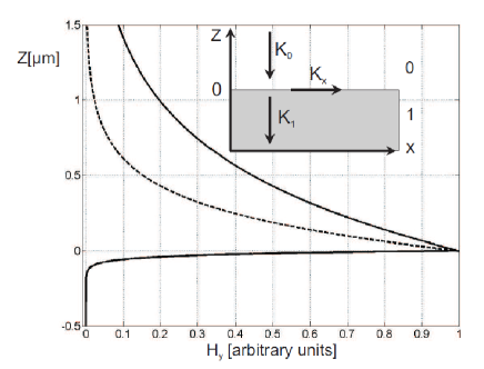
The product is positive if , a fact which is indeed true for silver and gold interfaces with air or glass in most of the visible optical domain. However small negative values of Eq. 8 occur for silver close to the interband region around . Additionally a higher value of will also change the sign in Eq. 8. Fig. 1 shows the behavior of the SPP magnetic field close to an interface gold/air and gold/glass at the optical wavelength nm. At such a wavelength the conditions given by Eqs. 5-8 impose the solutions
| (9) |
The real parts of the components of the SPP wave vector are for both media oriented in the same direction corresponding to a wave propagating from the air side to the metal side (see inset in Fig. 1). Furthermore the waves are exponentially damped when going away from the interface in agreement with Eq. 7, 8 (see Fig. 1). Most important for us is that the Poynting vector Jackson is defined in the medium j by
| (10) |
On the dielectric side the energy flow is as expected oriented in
the direction of . However it can be
shown on the metal side and for wavelengths not too close from the
spectral region associated with the interband transition of gold
or silver that the energy flow in the x direction is oriented
oppositely to the wave vector since
is dominated by and since .
However the total energy flow in the x direction is oriented along . Additionally
in the z direction
is parallel to since dominate. This
implies in particular that the energy associated with the SPP wave
is absorbed by the metal during its propagation through the
interface from the air side to the glass side. It should be
observed that already in the case of the ideal plasma model
neglecting losses the wave vector is antiparallel to
in the metal since there is no imaginary part and since
(see also Zhinzhin ; Kats ).
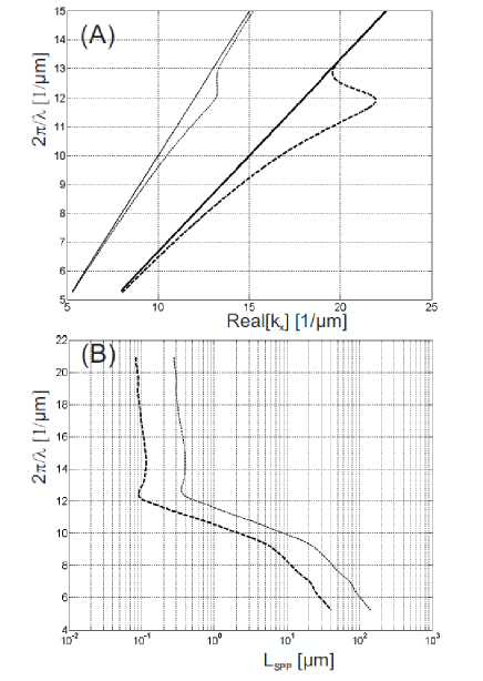
We show in Fig. 2 the curves associated with the dispersion
relations of SPPs propagating along a gold/air and gold/glass
interface respectively. Fig. 2A represents the dependencies
versus corresponding to Eq. 3. Fig. 2B shows the
dependencies versus where
is the propagation length of the SPP waves (for the metal optical
constant we used the experimental values given in Johnson ).
The typical back bending around corresponds to
the resonance associated with the bound electrons and the
interband transition (for a good discussion see
Novotny:2006 ). Far away from the interband the real part of
the dispersion is close to the asymptotic light lines: we speak
about Zenneck surface modes by opposition to Fano and evanescent
modes existing close to the interband Zhinzhin ; Halevi .
An important feature occurs close to this interband transition
since the slope in Fig. 2A is diverging. This means that the group
velocity defined by is
infinite. One can qualitatively deduce that there is however no paradox with causality by remarking that the
propagation length is approaching zero at such wavelengths.
Actually the SPP life time defined by is tending as well to zero. This is a
clear signature of the absence of significant SPP propagation in the
interband spectral region. This fact actually precludes faster than light information
transfer by SPP waves and is in agreement with relativistic causality.
A second important feature concerning Fig. 2 A is that the
air/gold dispersion curve is located inside of the light cone for
glass defined by the equation
where
is a real light wave vector and
. Writing
the wavevector of a TM (i. e., p polarized) plane wave propagating
away from the interfaces into the glass side one see that SPPs
propagating at the air/metal interface can radiate into the glass
substrate if the condition
| (11) |
is approximately fulfilled.
Here we neglected the role of the imaginary part in Eq. 3. Similarly one can deduce that none of the SPPs propagating at the
two interfaces can radiates into the air side.
In order to have a more complete analysis one must actually consider the
problem with two coupled interface 0/1 (glass/metal) and 1/2 (metal/air) supporting SPP
waves and separated by a small distance . The two interfaces are coupled by evanescent SPP waves tunnelling through the metal slab.
Such a mathematical problem can only be treated numerically by resolving an implicit equation. As
for the single interface this equation can be defined
directly from Maxwell Equations Burke . However it is much easier and convenient for the following
to remark with Raether Raether that Eq. 2 and consequently Eq. 3 are
obtained by finding the zeros of the numerator in the Fresnel
reflectivity coefficient for a TM wave coming from the dielectric
side:
| (12) |
with . Actually Raether Raether reasoned with the denominator of the Fresnel coefficient due to different conventions for the signs of the wave vectors . However it is remarkable that the result is the same at the end of the calculations. Identically one can thus define the Fresnel coefficient for a TM wave reflected by the slab 0-1-2 Jackson ; Novotny:2006 ; Raether :
| (13) |
and find the zeros of the numerator, i. e., one can solve the implicit equation
| (14) |
in order to define the SPP dispersion relations. From this equation it follows that
| (15) |
As for the single interface one has an important relation between the real and imaginary parts of the SPP wave vectors in the different medium:
| (16) |
Since we are interested only into the solutions which are decaying along the interface we (in agreement with our previous treatment of the single interface) suppose the condition satisfied. A second important point is that due to the arbitrariness in the sign of there are in fact apriori 8 possibilities for writing Eq. 15. However, Eq. 15 is invariant under the transformation . This means that the number of apriori possibilities for the sign of is reduced from 8 to 4. This multiplicity was studied by Burke et al. Burke however since for the present purpose we are looking for SPP waves leaking from the air/metal interface into the glass substrate we will consider only the possibility
| (17) |
The sign of is however arbitrary as explained above and we choose it here positive by definition. In order to define a SPP wave leaking into the glass substrate one has thus to substitute Eq. 17 into Eq.15 and find numerically (i. e., by a minimization procedure Hohenau ; Dionne ) the zeros of the implicit equation with variable and .
This has to be done only in the quarter of the complex plane corresponding to , . The quarter , must be equivalent due to symmetry and corresponds actually to decaying SPP waves propagating in the negative x direction. The two other quarters of the complex plane correspond to growing SPP waves along the interface and will be rejected on a physical ground (compare Burke ).
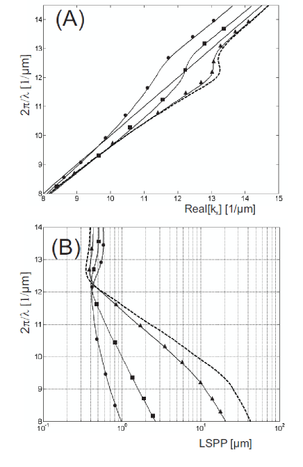
Figs. 3A and 3B show numerical calculations of dispersion relations corresponding to a SPP wave leaking through a gold film from the air side to the glass side. The thickness is taken to be =70, 50, 20, and 10 nm respectively. For the value nm the dispersion relation is identical to the dispersion for the single air/gold interface for semi infinite media. However, for smaller thickness the coupling between the interface increases and the propagation length decreases as shown on Fig. 3 B.
The magnetic field associated with SPP electromagnetic modes in this layered system is given by
| (18) |
The coefficients are obtained by considering the boundary conditions and one finds
| (19) |
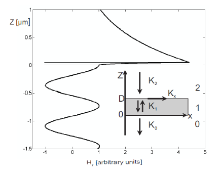
As an illustration we show in Fig. 4 the evolution of the real part of the magnetic field across a 50 nm thick gold slab sandwiched between the glass substratum and the air superstratum for an optical wavelength . As visible the SPP field is located in the vicinity of the air/gold interface and is evanescent on the air side. This is clearly reminiscent of our former analysis of SPPs propagating at the single air/metal. In addition however the wave is leaking radiatively (i. e., propagatively) into the glass substrate. However from Eq. 18 and the condition it is clear that the leaking wave is exponentially growing in the -z direction when going away from the gold slab. This is already the result we obtained when we considered the limit of the thick slab. An exponentially growing wave looks non physical and is in particular associated with infinite radiated energy in the far field. There is now the question of how to connect a growing wave with the basic reasoning giving rise to Eq. 11 and the idea of phase matching between the (real part) of the SPP wave vector with a propagative plane wave vector in the glass substrate. However such paradoxes disappear for two reasons: First, an infinite energy occurs only because we considered an infinite interface or equivalently because we did not consider how the SPP is locally launched on the metal film. When such conditions are taken into account this paradox must disappear Burke . Second, the SPP wave defined by Eq. 18 is actually a wave packet when looked at through the Fourier basis of propagative TM plane waves. Since in the far field (i. e., in the glass substrate) one actually detect such plane waves one must do a Fourier transform in order to generalize Eq. 11 Raether ; Burke . Instead of Eq. 11 one obtains consequently a statistical distribution of (real) wavevectors given by
| (20) |
where defines the full width at half maximum (FWHM) of this Lorentz distribution of radiated plane waves. By noting as usual the angle between the wave vectors of the plane waves refracted into the glass substrate and the normal to the interfaces one has by definition and the angular distribution of radiated power is in the far field given by:
| (21) |
III Leakage radiation microscopy
Historically the first observations of leakage radiation by SPP propagating on a thin metal film were reported by analyzing scattering by rough metal surfaces of light into SPPs Raether ; Simon . The possibility of using rough surface to excite SPPs was extensively studied in the past Raether and is based on the fact that the scattering by small defects on a flat film can represent a source of evanescent momentum sufficient for the light waves to match the SPP dispersion relation. Equivalently the amount of momentum needed can be carried by grating coupling Raether . SPP waves are subsequently emitted back into the glass substrate as leakage radiation (see Fig. 5).
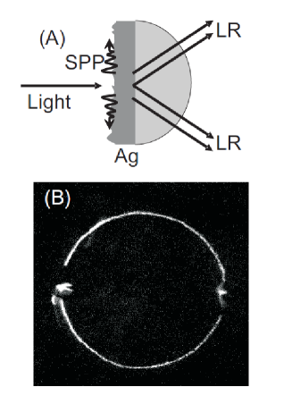
This light collected on a photographic plate forms a ring-like distribution in agreement with Eqs. 11, 20, 21. The FWHM of the SPP wavevector distribution is in direct correspondence with the radial width of the ring Simon . Further progress was obtained recently with the development of near field scanning optical microscopy (NSOM) which allows the local optical excitation of evanescent waves in the vicinity of a metal surface. Such evanescent waves can carry a sufficient amount of momentum to couple to SPP waves. Direct observations have indeed confirmed this principle Sonnichsen ; Brun:2003 ; Hecht . As an example we show in Fig. 6 an experiment in which the NSOM tip launches SPPs on an aluminum film which after interaction with a hole excites optically some quantum dots (QDs) located below. The collected signal shows a specific QD luminescence spectrum Brun:2002 . By scanning the sample around the NSOM tip one can realize SPP mapping since the hole acts a probe structure for the field emitted by the tip. Quantitative analysis of the total luninescence of the QDs associated with a given hole show clearly that the QD excitation is mediated by SPPs propagating on the aluminum film.
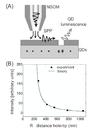
Fig. 6B shows the radial dependence of the collected intensity. These results agree well with a 2D SPP dipole model supposing an effective dipole located at the tip apex Hecht ; Brun:2003 (see also the discussions concerning the Bethe-Bouwkamp Bethe ; Bouwkamp1 ; Bouwkamp2 theory of diffraction by a small aperture in a metal film in Karrai1 ; Karrai2 ; Drezet:EPL2001 ; Drezet:PRE2002 ; Drezet:EPL2004 ). Following this model the SPP wave can be theoretically modelled by a scalar wave given by
| (22) |
where is given by Eq. 3, are polar coordinates on the metal film and the origin of
the coordinate is taken at the dipole position. is the
angle between the dipole associated with the NSOM tip (parallel to
the polarization of the laser beam injected in the NSOM tip) and
the the radial vector . This simplified model
can be theoretically justified by using the Green Dyadic Formalism
Bozhe and has been applied by many authors successfully
Hecht ; Bouhelier ; Brun:2003 ; Harry1 ; Harry2 ; Drezet:APL2005 ; Laluet
to SPP waves propagating in various environments.
Several authors applied NSOM methods coupled to LRM
Hecht ; Bouhelier . In particular in Hecht Hecht
et al. realized an optical setup using an immersion oil
objective to collect the leakage radiation emitted by the NSOM tip
on gold or silver films (see fig. 7).
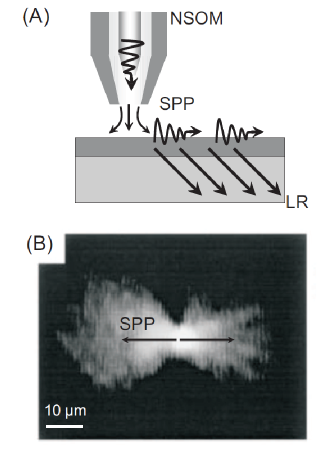
The system shown in Fig. 7 B is a 60 nm thick silver film
optically excited by a NSOM tip at the laser wavelength
. It can be shown by analyzing Fig. 7 B that the
radiation pattern is well described by a 2D dipole model in
agreement with Eq. 22. In particular the SPP propagation length
was measured and is in fair agreement with our analysis in
Sect. 1. Additionally it was shown in Hecht that one can
also analyze the Fourier distribution of SPP momentum (given by
Eqs. 20, 21)
by defocusing the objective lens. As expected SPP rings similar to the one of Fig. 5 were observed.
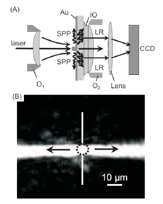
In the same context we developed in recent years a systematic approach using far-field microscopy to analyze quantitatively the interaction between SPPs and plasmonic devices by using LRM. The nanodevices studied were all fabricated by electron beam lithography (EBL) allowing the precise and reproducible tailoring of metal and dielectric surfaces on a lateral size dimension down to 20 nm EBL . As an example we show in Fig. 8 B a LRM image obtained by using a gold ridge (50 nm height, 150 nm width) lithographed on a 50 nm thick gold film to launch two well collimated and counter propagating SPP beams. These beams are launched by focussing a laser beam with a microscope objective (10x, numerical aperture ) on the gold ridge. Scattering by the nanostructure gives rise to evanescent waves supplying the right amount of momentum necessary for generating a SPP wave. The optical LRM setup is sketched in Fig. 8 A. Leakage radiation emitted through the glass substrate is collected by an immersion oil objective (63x, numerical aperture, ). Light is subsequently refocussed on a charge coupled device (CCD) camera. The direct mapping of the SPP intensity with this method provides a one-to-one correspondence between the 2D SPP intensity and the image recorded on the CCD camera. It should be observed that an incident laser beam with diameter is in the focal plane (object plane) of the objective focussed into a disc of diameter (i. e., beam waist) such that
| (23) |
where is the focal length of the objective and the
divergence angle of the laser beam focussed on the sample. The
direct application of this version of the Heisenberg relation
Teich implies that the divergence angle of
the SPP beam launched on the metal film must equal the divergence
angle of the impinging laser beam. This result is in good
agreement with the experimental case shown in Fig. 8 with
mm, m and . Changing the
objective focal length is a straightforward means to
obtain different divergence angles (see for example Drezet:APL2006 ; Stepanov ; Drezet:EPL2006 ).
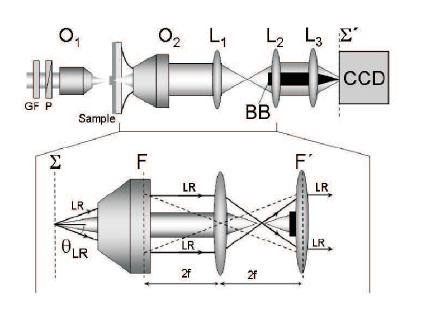
As a further improvement it is possible to modify the previous optical setup in order to image not only the direct space information but also the momentum corresponding to the Fourier space. It is indeed a well known fact of Fourier optics Teich ; Born ; Novotny:2006 that such a mapping of the wave vector distribution (as given by Eq. 20) is in principle always possible by recording the LR light in the back focal plane of the oil immersion objective. In the optical setup shown in Fig. 9 Drezet:APL2006 we realized a dual microscope able to image SPP propagation in both the direct and Fourier space. In particular the back focal plane of the oil immersion objective
imaged onto a CCD camera in Fig. 9. With such a microscope it is furthermore possible to act experimentally in the Fourier space image plane . First we can thereby remove the directly transmitted laser beam by using a beam block located on the optical axis. As an application of this method of filtering we consider the reflection of a SPP beam by an in-plane Bragg mirror. SPPs are launched as before from a gold ridge (50 nm height, 150 nm width) lithographed on a 50 nm thick gold film. The Bragg mirror Born constitutes a one-dimensional lattice of parallel gold ridges (50 nm height, 140 nm width) separated by a distance defining the period of the lattice. The period is connected to the SPP wavelength by and to the angle of incidence reflection of the SPP beam relatively to the (in plane) normal to the lattice by
| (24) |
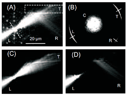
In the present case shown in Fig. 10 the Bragg mirror is optimized for (i. e., ) and for incidence angle which means . The experimental analysis of such a Bragg mirror when the resonance condition (, ) is fulfilled reveals a very high reflectivity of % (see, for example, Harry2 for some earlier results on SPP Bragg mirrors studied with fluorescence microscopy). However, in the present experiment we choose an incident angle . As a consequence the reflectivity was much lower (see Fig. 10 A and more details in Drezet:APL2006 ).
This configuration reveals SPP interferences in the vicinity of
the mirror (Fig. 10 A). In Fig. 10 B we show the corresponding
Fourier space image. The different observed arcs of LR rings
correspond to the reflected (R), and transmitted plus incident (T)
beams. The L beam is associated with a SPP launched in the
direction to the left, i. e, away from the mirror. C is the
directly transmitted laser beam distribution. By acting in the
Fourier plane image of the LRM microscope we now block the
information associated with the central beam and with the R or T
beams Drezet:APL2006 . Thereby the according SPP beam images
are erased from the image plane and consequently weak intensity
beams otherwise observed by interference can be directly
analyzed. For further analysis we extracted radial cross-cuts
along the white lines as shown in Fig. 10 B Drezet:APL2006 .
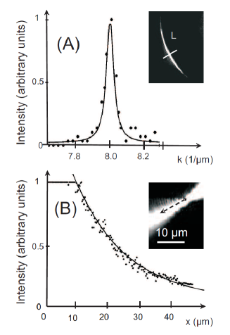
Results are shown in Fig. 11 A for the cross cut along . The
data points agree very well with a Lorentz fit given by Eqs. 20,
21. The FWHM of the Lorentzian distribution gives us a SPP
propagation length of m. This value is in
perfect agreement with the cross-cut made along the beam in
the direct space image 10 A (see Fig. 11 B).
Both data agree also with values given by the dispersion relations discussed in sect. 1 (see Figs. 2B and 3B).
LRM was subsequently applied by us to many SPP in-plane devices
such as beam splitters Stepanov , dielectric lenses, prisms
Hohenau and wave-guides Steinberger . In particular,
LRM experiments were compared to near field optical experiments (
photon scanning tunnelling microscopy) and showed good agreement
in the cases considered Hohenau ; Steinberger . LRM appears
thus in this context as a complementary far-field optical method
to NFO such as NSOM. LRM was applied as well for analyzing SPP
Bragg mirrors (with high reflectivity %),
interferometers Drezet:EPL2006 ; Drezet:plasmonics2006 and
SPP elliptical cavities Drezet:APL2005 or 2D SPP
microscopes submitted . In this context we observed
Drezet:EPL2006 stationary SPP waves with very high
visibility
by using LRM. This proves directly that SPP wave coherence is
conserved in LRM and can exploited for quantitative analysis down
to the spatial resolution limit . Actually SPP
interferometers such as the ones described in
Drezet:APL2005 ; Drezet:plasmonics2006 ; Harry2 reveal clear
interference pattern and oscillation characteristics of these
devices.
It is thus possible to develop 2D interferometry for SPP waves having all the advantages of current macroscopic interferometry techniques.
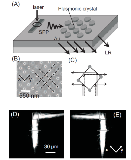
We also mention the realization of plasmonic crystals (i. e.,
photonic crystals for SPPs) which were studied using LRM (see
Fig. 12). In such devices Drezet:Nanolett2007 rectangular
2D latices made of gold nano-protrusions (200 nm diameter, 50 nm
height) deposited on a 50 nm thick gold film (see Fig. 12B) are
used to create photonic band gaps at specific SPP wavelengths
nm and nm (i. e.,
laser wavelengths of respectively 750 nm and 800 nm) corresponding
to the two periods of the lattice nm and nm. The existence of
these band gaps implies that SPP plane waves impinging on small
devices build up with such lattice will generate stationary waves
in the crystal. More precisely this implies that SPPs will be
reflected in specific and different directions if their
wavelengths match the values or and if the
angle of incidence relatively to the normal to the Bragg planes of
the crystal (Figs. 12 B, C) equals . Such devices act
consequently as an efficient in-plane wavelength demultiplexer for
SPPs Drezet:Nanolett2007 as it was indeed observed
experimentally (see Fig. 12D and E). While the results discussed
here were achieved within the visible spectral range, plasmonic
crystal devices are expected to perform even better (e.g., in
terms of spectral selectivity) in the infrared (telecom) spectral
range due to significantly lower ohmic losses
Nikolajsen:2003 . In general, the use of multiplexers,
splitters and tritters Drezet:Nanolett2007 in photonic
applications might be specifically appealing due to their small
footprint in the range of m2. Furthermore,
the use as building blocks for classical Teich or quantum
Knill:2001 optical
computing can be envisaged.
IV Conclusion
In this article we reviewed the field of leakage radiation microscopy (LRM) theoretically and experimentally. Theoretically we analyzed how SPP can generate leaky wave in the glass substrate by tunnelling from the air side through a thin metal film supporting SPP waves. We showed in particular that for thick film ( nm) leakage radiation (LR) does not affect the dispersion relation on the air/metal interface. Importantly the angular distribution of LR is located on a cone matching the SPP dispersion relation. We also reviewed the first experimental results reporting the observation of LR on rough surface and using near field optics methods. We analyzed more recent application of LRM to SPP nano-devices fabricated by electron beam lithography. From all these results we can conclude that LRM is a convenient and versatile far field optical method for analyzing quantitatively SPP propagation on flat film and their interaction with various nano-devices of direct practical interest. Such versatility positions LRM as an appealing alternative to near field optics for studying SPP propagation on a scale of, or larger than the wavelength.
For financial support the European Union, under project FP6 2002-IST-1-507879 is acknowledged.
References
- (1) H. Raether, Surface Plasmons(Springer, Berlin, 1988).
- (2) W. L. Barnes , A. Dereux, T. W. Ebbesen, Nature 424, (2003) 824.
- (3) C. Genet, T. W. Ebbesen, Nature 445, (2007) 39.
- (4) A. Drezet, A. Hohenau, J. R. Krenn, M. Brun, S. Huant, Micron 38, (2007) 427.
- (5) D. W. Pohl, W. Denk, M. Lanz, Appl. Phys. Let. 44, (1994) 651.
- (6) D. Courjon, Near-field microscopy and near-field optics ( Imperial College Press, London, 2003).
- (7) J. R. Krenn, A. Dereux, J. C. Weeber, E. Bourillot, Y. Lacroute, J. P. Goudonnet, G. Schider, W. Gotschy, A. Leitner, F. R. Aussenegg, C. Girard, Phys. Rev. Lett. 82, (1999) 2590.
- (8) B. Hecht, H. Bielefeldt, L. Novotny, Y. Inouye, and D. W. Pohl, Phys. Rev. Lett. 77, (1996) 1889.
- (9) A. Bouhelier, Th. Huser, H. Tamaru, H. -J. Güntherodt, D. W. Pohl, Fadi I. Baida and D. Van Labeke, Phys. Rev. B. 63, (2001) 155404.
- (10) A. Stepanov, J. R. Krenn, H. Ditlbacher, A. Hohenau, A. Drezet, B. Steinberger, A. Leitner, and F. Aussenegg, Opt. Lett. 30,(2005) 1524.
- (11) J. J. Burke, G. I. Stegeman, T. Tamir, Phys. Rev. B 33, (1986) 5186.
- (12) J. D. Jackson, Classical Electrodynamics (J. Wiley and Sons, New York, 1975).
- (13) G. N. ZhiZhin, M. A. Moskalova, E. V. Shomina and V. A. Yakovlev in Surface Polaritons, edited by V. Agranovich and D. L. Mills (North-Holland Publishing Company, Amsterdam, 1982) pp. 93-143.
- (14) A. V. Kats, S. Savel’ev, V. A. Yampol’skii, F. Nori, Phys. Rev. Lett. 98, (2007) 073901.
- (15) P. B. Johnson and R. W. Christy, Phys. Rev. B 6, (1972) 4370.
- (16) P. Halevi in Electromagnetic Surface modes edited by A. E. Boardman (John Wiley, New York, 1982) Chap. 7.
- (17) L. Novotny, B. Hecht, Principles of Nano-Optics (Cambridge Press, London 2006).
- (18) A. Hohenau, J. R. Krenn, A. L. Stepanov, A. Drezet, H. Ditlbacher, B. Steinberger, A. Leitner, F. R. Ausseneg, Opt. Lett. 30, (2005) 893.
- (19) J. A. Dionne, L. A. Sweatlock, H. A. Atwater, A. Polman, Phys. Rev. B 72, (2005) 075405.
- (20) H. J Simon, J. K. Guha, Opt. Comm. 18, (1976) 391.
- (21) C. Sönnichsen, A. C. Duch, G. Steiniger, M. Koch, G. vonPlessen, J. Feldmann, Appl. Phys. Lett. 76, (2000) 140.
- (22) M. Brun, A. Drezet, H. Mariette, N. Chevalier, J. C. Woehl, S. Huant, Europhys. Lett. 64, (2003) 634.
- (23) M. Brun, S. Huant, J. C. Woehl, J.-F. Motte, L. Marsal, H. Mariette, Solid State Comm. 121, (2002) 407.
- (24) H. A. Bethe, Phys. Rev. 66, (1944) 163.
- (25) C. J. Bouwkamp, Philips Res. Rep. 5, (1950) 321.
- (26) C. J. Bouwkamp, Philips Res. Rep. 5, (1950) 401.
- (27) C. Obermuüller and K. Karrai, Appl. Phys. Lett. 67, (1995) 3408.
- (28) C. Obermüller, K. Karrai, G. Kolb, and G. Abstreiter, Ultramicroscopy 61, (1995) 171.
- (29) A. Drezet, J. C. Woehl, and S. Huant, Europhys. Lett. 54, (2001) 736.
- (30) A. Drezet, S. Huant, and J. C. Woehl, Europhys. Lett. 66, (2004) 41.
- (31) A. Drezet, J. C. Woehl, and S. Huant, Phys. Rev. E65, (2002) 046611.
- (32) T. Søndergaard, S. I. Bozhevolnyi, Phys. Rev. B69, (2004) 045422.
- (33) H. Ditlbacher, J. R. Krenn, N. Felidj, B. Lamprecht, G. Schider, M. Salemo, A. Leitner, and F. R. Aussenegg, Appl. Phys. Lett. 80, (2002) 404.
- (34) H. Ditlbacher, J. R. Krenn, G. Schider, A. Leitner, and F. R. Aussenegg, Appl. Phys. Lett. 81, (2002) 1762.
- (35) A. Drezet, A. L. Stepanov, H. Ditlbacher, A. Hohenau, B. Steinberger, F. R. Aussenegg, A. Leitner, and J. R. Krenn, Appl. Phys. Lett. 86, (2005) 074104.
- (36) J.-Y. Laluet, E. Devaux, C. Genet and T. W. Ebbesen, J.-C. Weeber and A. Dereux, Opt. Express 15, (2007) 3488.
- (37) M. A. McCord and M. J. Rooks, in Handbook of Microlithography, Micromachining and Microfabrication, Volume 1 edited by P. Rai-Choudhury (SPIE and The Institution of Electrical Engineers, Bellingham, Washington, 1997), pp. 139-249.
- (38) Saleh, B. E. A., Teich, M. C. Fundamentals of Photonics (Wiley, New York, 1991).
- (39) A. Drezet, A. Hohenau, A. Stepanov, H. Ditlbacher, B. Steinberger, N. Galler, F. R. Aussenegg, A. Leitner, J. R. Krenn, Appl. Phys. Lett. 89, (2006) 091117.
- (40) A. Drezet, A. L. Stepanov, A. Hohenau, B. Steinberger, N. Galler, H. Ditlbacher, A. Leitner, F. R. Aussenegg, J. R. Krenn, M. U. Gonzalez, J.-C. Weeber, Europhys. Lett. 74, (2006) 693.
- (41) M. Born and E. Wolf, Principles of Optics, seventh (expanded ) edition (Cambridge University Press, Cambridge, 1999).
- (42) B. Steinberger, A. Hohenau, H. Ditlbacher, A. L. Stepanov, A. Drezet, F. R. Aussenegg, A. Leitner, J. R. Krenn Appl. Phys. Lett. 88, (2006) 09410 .
- (43) A. Drezet, A. Hohenau, A. Stepanov, H. Ditlbacher, B. Steinberger, F. R. Aussenegg, A. Leitner, J. R. Krenn , Plasmonics 1, (2006) 141.
- (44) A. Drezet, D. Koller, A. Hohenau, F. R. Aussenegg, A. Leitner, J. R. Krenn , submitted (2007).
- (45) A. Drezet, D. Koller, A. Hohenau, J. R. Krenn, Nanoletters (Mai 2007) DOI: 10.1021/nl070682p.
- (46) T. Nikolajsen, K. Leosson, I. Salakhutdinov, S. I. Bozhevolnyi Appl. Phys. Lett. 82, (2003) 668.
- (47) E. Knill, R. Laflamme, G. J. Milburn, Nature 409, (2001) 46.