Measurement crosstalk between two phase qubits coupled by a coplanar waveguide
Abstract
We analyze the measurement crosstalk between two flux-biased phase qubits coupled by a resonant coplanar waveguide cavity. After the first qubit is measured, the superconducting phase can undergo damped oscillations resulting in an a.c. voltage that produces a frequency chirped noise signal whose frequency crosses that of the cavity. We show experimentally that the coplanar waveguide cavity acts as a bandpass filter that can significantly reduce the crosstalk signal seen by the second qubit when its frequency is far from the cavity’s resonant frequency. We present a simple classical description of the qubit behavior that agrees well with the experimental data. These results suggest that measurement crosstalk between superconducting phase qubits can be reduced by use of linear or possibly nonlinear resonant cavities as coupling elements.
In recent years, much effort has been spent fabricating superconducting circuits with embedded Josephson junctions (JJs) as a promising platform for developing a quantum computer. In particular, superconducting qubits, broadly classified as charge, flux, and phase[Forarecentreviewsee][andreferencestherein]ClarkeN2008, have recently achieved coherence time longer than 7 sWallraffPRL2005 , and single shot visibility close to 90%LupascuPRL2006 ; *MartinisQIP2009. Various schemes have been devised to couple several qubits in a more complex circuit: coupling through JJsGrajcarPRL2006 , inductive couplingNiskanenSci2007 ; *NiskanenPRB2006, capacitive couplingMcDermottSci2005 and coupling through a resonant coplanar waveguideMajerNat2007 ; Sillanpaeae2007 ; AnsmannN2009 (CPW) cavity have all been achieved. The quantum mechanical nature of CPW cavities has also been demonstrated by generating arbitrary Fock states through the use of a coupled phase qubitHofheinzN2009 . Additionally, a protocol for the preparation of arbitrary entangled states of two phase qubits and a CPW cavity has been developedAltomareX2009 .
Here, we will focus on two flux-biased phase qubitsSimmondsPRL2004 coupled through a CPW cavitySillanpaeae2007 ; AltomareX2009 ; AnsmannN2009 and will show how the CPW cavity plays a crucial role in the reduction of measurement crosstalkSillanpaeae2007 ; AnsmannN2009 .
Measurement crosstalk in coupled flux-biased phase qubitsMcDermottSci2005 ; kofmanprb2007 results from their unique formation in a metastable well of a double-well potential and the measurement scheme used for determining the qubit state. The schematic of a typical phase qubit111In the remainder, we will refer to the flux-biased phase qubit simply as a phase qubit circuit is shown in Fig. 1(a). The phase qubit is essentially a resonant LC circuit in parallel with a Josephson inductance (), where is th flux quantum, is the flux applied to the circuit loop and the JJ critical current. The potential energy as a function of the superconducting phase difference () across the JJ is presented in Fig. 1(b) for a particular flux bias. With a relatively strong anharmonicity, the quantized energy levels in the left well can be individually addressed with transition frequencies between the lowest quantized state () and the first excited state () in the microwave region. The occupation probability of the qubit’s first excited state is measured by applying a fast flux pulse or measure pulse (MP) that tilts the well for a few nanosecondsCooperPRL2004 so that only the state can tunnel out to the right well, as shown in Fig. 1(c). Because the phase qubit is formed in a metastable region of the potential, its ’ground state’ energy is naturally higher than the global ground state of the system. Upon tunneling, this additional energy is released so that the phase of the qubit (classically) undergoes large oscillations in the deeper right well. Following the MP the flux is adjusted to form a symmetric double-well potential. After tens of microseconds, when the system has relaxed due to dissipation, a DC SQUID detects the flux in the qubit loop, allowing us to discriminate between the two circulating current states where the phase either relaxed in the left well or the right well. These correspond to the qubit states if the qubit did not tunnel and if the qubit did tunnel.
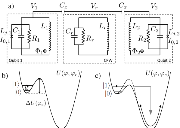
The oscillations of the qubit phase in the right well produce an oscillating voltage across the JJJosephsonRMP1974 with a relatively large size, representing roughly hundreds of microwave quanta. This voltage signal can excite any devices coupled to the qubit when their resonant frequency matches that of the oscillation. Because the right well potential is weakly anharmonic, as the amplitude decreases due to dissipation the frequency rises, producing a chirp crosstalk signal spanning over 10 GHz. With direct capacitive coupling between two phase qubitsMcDermottSci2005 , this process results in the second qubit being excited over its metastable barrier whenever the first qubit is measured in the state. Due to the nonlinear dynamics of the system, there is a finite amount of time required (several nanoseconds) for the second qubit to be excited after the tunneling of the first qubit. It was found that the loss of qubit information due to measurement crosstalk could be avoided by measuring the two qubits simultaneouslyMcDermottSci2005 (within ns). A classical description of the qubit dynamics was found to sufficiently model the observed measurement crosstalk behaviorMcDermottSci2005 ; kofmanprb2007 . Unfortunately, the excess energy released by a metastable phase qubit during a tunnelling event is unavoidable, so that measurement crosstalk can be a serious problem for systems with many coupled qubits.
The situation is quite different if two phase qubits are coupled through a CPW cavity. Here we show both experimentally and using the classical description of Ref. kofmanprb2007, that the CPW cavity acts as a bandpass filter, and the second device is excited only if it is in resonance with the CPW cavity. This suggests a simple and effective way to reduce the measurement crosstalk between coupled devices and has recently been implementedAnsmannN2009 .
The device we use has already been described elsewhere AltomareX2009 , and consists of two flux-biased phase qubits capacitively coupled through a 7 mm open-ended coplanar waveguide whose half-wave resonant mode frequency is GHz. All the measurements are performed at a temperature of 35 mK in a dilution refrigerator. The qubits are controlled through heavily filtered (low pass) flux bias lines, while the microwave lines are attenuated at various stages in the cryostat. Figure 1(a) shows the equivalent electrical circuit for the device. The dissipation in the circuit is modelled using the RSJ modelbarone1982physics ; likharev1986dynamics ; vanduzer1981principles . The CPW cavity, with characteristic impedance close to resonance, is equivalent to a lumped element resonator with , . The lifetime of an excitation in the CPW cavitySimmondsQIP2009 is s, which yields . The qubit’s parameters are: pH, pF, A, ns, , and pH, pF, A, ns, , with fF. As discussed in Ref. AltomareX2009, , the resonant frequency of both qubits exhibits an avoided crossing at the CPW cavity frequency ( GHz). For the first qubit this happens at a flux , and for the second at a flux . For each qubit, is the critical flux at which the left well of Fig. 1(b) disappears.
For our experiment, we initially
determineMcDermottSci2005 ; Sillanpaeae2007 ; AltomareX2009 the
optimal ’simultaneous’ timing between the two MPs that takes into
account the different cabling and instrumental delays from the
room-temperature equipment to the cold devices. Then, as a function
of the flux applied to the two qubits, we measure the tunneling
probability for the second (first) qubit after we purposely induce
a tunneling event in the first (second) qubit. The results are
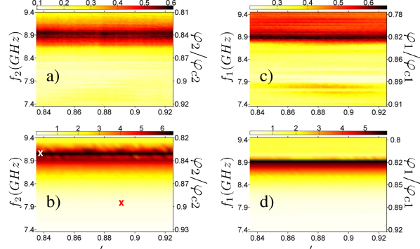
shown in Fig. 2(a,c). The probability of
finding the second (first) qubit in the excited state as a result
of measurement crosstalk is significant only in a region around
() where the resonant
frequency of the second (first) qubit is close to the CPW cavity
frequency.
To provide a qualitative description of these results, we write the Lagrangiankofmanprb2007 for the two qubits coupled through a CPW cavity (Fig. 1 (a)) as
| (1) |
where is the potential energy in the CPW cavity, and the potential energy of the qubit is
| (2) |
with . The dimensionless flux, , determines the profile of the potential energy for the qubit. Using the Josephson relations (to substitute with ) and solving for the equation of motion, after including the damping term, we obtain222To speed up the calculations, the damping term for the CPW cavity and the second qubit have been omitted:
| (3) |
where .
As can be seen from Eq. 3, the treatment of the qubits and the CPW cavity is fully classical. The initial conditions for the solution of this system of differential equations are described below. The second qubit and the oscillator begin with zero kinetic energy () and have zero potential energy; zero energy is defined at the bottom of the left well. To understand the initial conditions for the first qubit it is useful to recall the physics of the measurement. When the MP is applied, the flux approaches the critical value (approximately ) over a short period of time, so that the first excited state tunnels out with unit probability. Once tunneled, this qubit can be assumed to have zero kinetic energy (), to have a phase value just to the right side of the residual local maximum between the two wells (Fig. 1(b)), giving it an initial potential energy below the local maximum valuekofmanprb2007 . In addition, we assume that the decay rate in the right well is comparable to that in the left well, and the simulation is run for times , after which the qubit phase has relaxed to rest. We have checked that small variations in these assumptions do not meaningfully affect the results of our simulations.
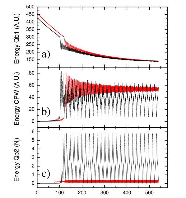
From these initial conditions the phase of the first qubit(classically) undergoes damped oscillations in the anharmonic right well. Because of the anharmonicity of the potential, when the amplitude of the oscillation is large, the frequency of the oscillations is lower than the unmeasured qubit frequency. As the system loses energy due to the damping, the oscillation frequency increases as seen by the CPW cavity. When the crosstalk voltage has a frequency close to the CPW cavity frequency, it can transfer energy to the CPW cavity. If the second qubit’s frequency matches that of the CPW cavity then the cavity’s excitation can be transferred to the second qubit. In Fig. 2(b) we plot, for the second qubit, the ratio () between the maximum energy acquired and , where is the plasma frequency of the qubit in the left well, as a function of the fluxes in the two qubits. The crosstalk, measured as the maximum energy transferred to the second qubit, is maximum at a flux , where the second qubit’s frequency is , determined by taking the Fast Fourier Transform of the oscillations in energy over time (see Fig. 3 (a-c)). Reversing the roles of the two qubits, we find that for the first qubit the crosstalk is maximum at a flux , corresponding to an excitation frequency of (Fig. 2(d)). These values were determined for qubit 2 (qubit 1) by performing a Gaussian fit of versus flux (or frequency) after averaging over the span of flux (or frequency) values for qubit 1 (qubit 2). Notice that the crosstalk transferred to qubit 2 (qubit 1) is flux independent of qubit 1 (qubit 2) and substantial only when the cavity frequency matches the frequency of qubit 2 (qubit 1). The results of the simulations are in good agreement with the experimental data. To gain additional insight into the dynamics of the system, we plot the time evolution of the energy for the qubits and the CPW cavity (Fig. 3 (a-c)) for two different sets of fluxes in the two qubits. At and (red x in Fig. 2(b)) the first qubit decays exponentially for a time (Fig. 3 (a-c)-Red). At there is a downward jump in the energy of the first qubit while the energy of the CPW cavity exhibits an upward jump. At this time, the frequency of oscillation in the right well matches the CPW cavity resonant frequency, so part of the qubit energy is transferred to the CPW cavity. However, since the second qubit is not on resonance with the CPW cavity, it does not get significantly excited by the microwave current passing through the capacitor .
At and (white x in Fig. 2(b)), the dynamics of the first qubit and the CPW cavity are essentially unchanged, except that the CPW cavity frequency is matched at a different time () because the first qubit starts at a lower energy in the deep well (Fig. 3 (a-c)-Black). However, in this case, the second qubit is on resonance with the CPW cavity and is therefore excited to an energy .
The presence of the MP in the actual experiment does not change the agreement between the experiment and the simulation. In fact, the excitation arrives at the second qubit several nanoseconds after the first qubit has been measured. Because of the finite tunneling probability of the higher levels of the qubit, this excitation can be sufficient to allow the qubit to tunnel through the barrier.
We have shown experimental results for measurement crosstalk between two metastable phase qubits coupled by a resonant cavity. These results have been described classically and verified by a full simulation of the system. We have confirmed that the resonant cavity acts as a bandpass filter reducing the detrimental affects of measurement crosstalk as long as the qubits are detuned from the cavity resonance. In the future, it may be interesting to investigate the transfer of measurement crosstalk through an anharmonic resonant cavity whose frequency versus amplitude characteristic may eliminate crosstalk completely. Ultimately, future device architectures incorporating multiple metastable phase qubits can benefit from the use of resonant cavities between the qubits to prevent measurement crosstalk. This will improve the fidelity and reduce errors in the measurement of entangled qubit statesAltomareX2009 ; KofmanPRB2008 ; AnsmannN2009 .
This work was financially supported by NIST. Contribution of the U.S. government, not subject to copyright. M.A.S. was supported by the Academy of Finland, and by the ERC (grant No. FP7-240387).
References
- (1) J. Clarke and F. K. Wilhelm, Nature 453, 1031 (2008)
- (2) A. Wallraff, D. I. Schuster, A. Blais, L. Frunzio, J. Majer, M. H. Devoret, S. M. Girvin, and R. J. Schoelkopf, Phys. Rev. Lett. 95, 060501 (2005)
- (3) A. Lupaşcu, E. F. C. Driessen, L. Roschier, C. J. P. M. Harmans, and J. E. Mooij, Phys. Rev. Lett. 96, 127003 (2006)
- (4) J. M. Martinis, Quantum Information Processing 8, 81 (2009)
- (5) M. Grajcar, A. Izmalkov, S. H. W. van der Ploeg, S. Linzen, T. Plecenik, T. Wagner, U. Hübner, E. Ilichev, H.-G. Meyer, A. Y. Smirnov, P. J. Love, A. Maassen van den Brink, M. H. S. Amin, S. Uchaikin, and A. M. Zagoskin, Phys. Rev. Lett. 96, 047006 (2006)
- (6) A. O. Niskanen, K. Harrabi, F. Yoshihara, Y. Nakamura, S. Lloyd, and J. S. Tsai, Science 316, 723 (2007)
- (7) A. O. Niskanen, K. Harrabi, F. Yoshihara, Y. Nakamura, and J. S. Tsai, Phys. Rev. B 74, 220503(R) (2006)
- (8) R. McDermott, R. Simmonds, M. Steffen, K. Cooper, K. Cicak, K. Osborn, S. Oh, D. Pappas, and J. Martinis, Science 307, 1299 (2005)
- (9) J. Majer, J. M. Chow, J. M. Gambetta, J. Koch, B. R. Johnson, J. A. Schreier, L. Frunzio, D. I. Schuster, A. A. Houck, A. Wallraff, A. Blais, M. H. Devoret, S. M. Girvin, and R. J. Schoelkopf, Nature (London) 449, 443 (2007)
- (10) M. A. Sillanpää, J. I. Park, and R. W. Simmonds, Nature (London) 449, 438 (2007)
- (11) M. Ansmann, H. Wang, R. C. Bialczak, M. Hofheinz, E. Lucero, M. Neeley, A. D. O’Connell, D. Sank, M. Weides, J. Wenner, A. N. Cleland, and J. M. Martinis, Nature (London) 461, 504 (2009)
- (12) M. Hofheinz, H. Wang, M. Ansmann, R. C. Bialczak, E. Lucero, M. Neeley, A. D. O’Connell, D. Sank, J. Wenner, J. M. Martinis, and A. N. Cleland, Nature (London) 459, 546 (2009)
- (13) F. Altomare, K. Cicak, M. A. Sillanpää, M. Allman, A. Sirois, J. A. Strong, D. Li, J. Park, J. D. Whittaker, and R. W. Simmonds, submitted to Nature Physics
- (14) R. W. Simmonds, K. M. Lang, D. A. Hite, S. Nam, D. P. Pappas, and J. M. Martinis, Phys. Rev. Lett. 93, 077003 (2004)
- (15) A. G. Kofman, Q. Zhang, J. M. Martinis, and A. N. Korotkov, Phys. Rev. B 75, 014524 (2007)
- (16) In the remainder, we will refer to the flux-biased phase qubit simply as a phase qubit
- (17) K. B. Cooper, M. Steffen, R. McDermott, R. W. Simmonds, S. Oh, D. A. Hite, D. P. Pappas, and J. M. Martinis, Phys. Rev. Lett. 93, 180401 (2004)
- (18) B. D. Josephson, Rev. Mod. Phys. 46, 251 (1974)
- (19) A. Barone and G. Paterno, Physics and Applications of the Josephson Effect. (Wiley, 1982)
- (20) K. Likharev, Dynamics of Josephson junctions and circuits (CRC, 1986)
- (21) T. Van Duzer and C. Turner, Principles of Superconducting Circuits (Elsevier, New York, 1981)
- (22) R. Simmonds, M. Allman, F. Altomare, K. Cicak, K. Osborn, J. Park, M. Sillanpää, A. Sirois, J. Strong, and J. Whittaker, QIP 8, 117 (2009)
- (23) To speed up the calculations, the damping term for the CPW cavity and the second qubit have been omitted
- (24) A. G. Kofman and A. N. Korotkov, Phys. Rev. B 77, 104502 (2008)