Ca-intercalated graphite as a hydrogen storage material: stability against decomposition into CaH2 and graphite
Abstract
We have used calculations based on density functional theory to investigate the energetics of hydrogen absorption in calcium-intercalated graphites. We focus particularly on the absorption energy and the stability of the hydrogenated material with respect to decomposition into graphite and calcium hydride, which is essential if this material is to be useful for practical H2 storage. The calculations are performed with two commonly used approximations for the exchange-correlation energies. Our calculations confirm earlier predictions that the absorption energy is approximately to eV, which is favourable for practical use of Ca-intercalated graphite as a hydrogen storage medium. However, we find that the hydrogenated material is strongly unstable against decomposition. Our results therefore explain recent experiments which show that H2 does not remain stable in CaC6 but instead forms a hydride plus graphite.
keywords:
DFT , Graphite , Intercalation , Calcium , Hydride , Hydrogen , Stability.1 Introduction
Finding an alternative, or secondary, energy source to replace petroleum for use in vehicles is of paramount importance. Hydrogen is a possible candidate and, with the advancement of proton exchange membrane (PEM) fuel cell technologies [1], could provide a viable energy solution. The practical ambient storage of hydrogen has long been a challenge [2, 3]. If hydrogen fuel cells are to be used in the transport industry then a lightweight energy dense storage medium needs to be found [4]. The U.S. Department of Energy state that a storage medium needs to store 6.5 [5] hydrogen by weight at ambient temperature and pressure. In order that the material can take in and release hydrogen at ambient temperature and reasonable pressures, the absorption energy also needs to be in the range eV ( eV kJ/mol).
Graphite intercalation compounds (GICs) have shown promise as a potential ambient high-density storage medium because they have a low density. They have the great advantage that their chemistry and the spacing between the carbon planes can be tuned [6, 7]. They are also inexpensive to produce. Many GICs have been considered for hydrogen storage and possess very different properties when hydrogen is introduced into them [8, 9, 10]. Recently calculations based on density functional theory (DFT) have been used to survey the binding energies of hydrogen in a wide range of metal-intercalated graphite materials [11]. The results showed that alkaline-earth intercalates appear to be very promising, because their calculated binding energies are in the required range. An essential requirement for the practical use of any of these GIC materials is that they should be stable against decomposition into the metal hydride and graphite. Very recent experiments [12] on the hydrogenation of calcium graphite (CaC6) suggest that this may be a major issue and that the attempted hydrogenation of the material leads to the formation of orthorhombic calcium hydride (CaH2) and the complete deintercalation of the starting CaC6 leaving graphite. This has also been shown to occur for lithium graphite (LiC6) [13]. Surprisingly, this crucial question of stability against decomposition does not appear to have been addressed before by modelling. The recent DFT work by Cobian and Íñiguez [11] on hydrogen storage in GIC materials did explore the question of stability against metal clustering, but did not consider the possibility of hydride formation.
The purpose of the present paper is to use electronic-structure methods to study the stability of hydrogenated Ca-intercalated graphite against decomposition into graphite and CaH2. The experiments of Srinivas et al. [12] indicate that this decomposition occurs spontaneously, so that it must be exothermic. This means that the Ca-GIC could not be used without modification as a hydrogen storage material. However, it is still possible that the hydrogenated material might become stable against decomposition if other atomic or molecular species were co-intercalated together with Ca. In considering whether and how this can be done, it is important to know the heat of decomposition of hydrogenated Ca-GIC. This important quantity is not available from the experiments, and our aim here is to use DFT to calculate it.
In the next section, we summarise the essential background information about Ca-GICs, and we also outline the DFT techniques used in this work. In section 3, we present our calculations, first on Ca-GIC (3.2) itself at various stoichiometries, then on the hydrogenated material (3.3), and finally on the CaH2 crystal (3.4). These calculations yield values of the heat of decomposition of hydrogenated Ca-GIC, computed with different DFT approximations. As expected, the decomposition is exothermic, and we discuss in section 4 the implications of our results.
2 Background information
2.1 The materials
The structure of graphite is well known to consist of planes of carbon atoms, with each plane having a hexagonal honeycomb structure. Different registrations of the carbon planes relative to each other are possible, the main two being (hexagonal, 2H) and (rhombohedral, 3R), with the 2H registration being most thermodynamically stable at standard temperature and pressure [14]. The nearest neighbour C-C distance is 1.42 Å. The layers are held together by weak van der Waals dispersion, a physical effect that is not included in standard forms of DFT. Nevertheless, it is known that the local density approximation (LDA) of DFT fortuitously predicts an equilibrium interplanar spacing (3.38 Å) that is very close to the experimental value (3.36 Å).
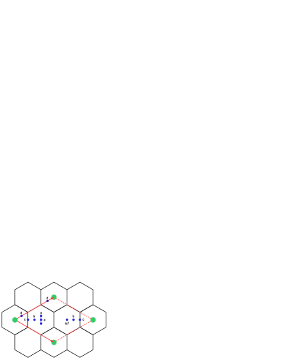
For Ca-intercalated graphite the registrations of the graphite layers are shifted so that carbon atoms superimpose each other producing an stacking. It has been shown by x-ray diffraction experiments [15] that the Ca intercalants are positioned directly above and below hexagon centres (see figure 1). The only experimentally observed stoichiometry is CaC6 in stacking (where we use the notation of Dresselhaus and Dresselhaus [6] with Greek letters labelling successive intercalant layers) such that each successive Ca layer is shifted relative to the preceding one resulting in a rhombohedral structure. This only exists as a stage \@slowromancapi@ GIC, where the staging numbers how many graphite layers exist between each intercalant layer. It is known that other GICs produce different stage GICs, in the case of KC24 a stage \@slowromancapii@ GIC. The interplanar spacing of Ca-GIC is increased with respect to graphite to 4.524 Å (a 35 increase over graphite) and the C-C in-plane nearest neighbour distance to 1.444 Å (a small 1.7 increase over graphite).
A definable crystal structure for the hydrogenated Ca-GIC is not observed experimentally [16]. Once hydrogenated the CaC6 diffraction peaks weaken in intensity and the reflections from the CaH2 structure become apparent. A weak unidentified peak appears but is too weak to relate to a major structure change.
The CaH2 crystal has an orthorhombic unit cell with symmetry (International Tables group 62). The unit cell consists of four CaH2 units at each of the Wyckoff 4c positions. This means that the crystal requires only the x- and z-coordinates of one Ca atom and of two inequivalent H atoms to fully describe it; the y-coordinate is fixed by symmetry. The Wyckoff 4c positions are given in table 3. Experimental structural parameters of the crystal have been reported by Wu et al. [17], and calculations on the structure have been performed by Li et al. [18] and Wolverton and Ozolins [19].
2.2 Electronic-structure techniques
This work employs standard electronic-structure methods based on DFT, applied to periodically repeated simulation cells. At the temperature of interest, electronic excitations are negligible, and all the predictions are derived from the electronic ground state energy of the system and the forces on the ions for given ionic positions. We use the projector augmented wave (PAW) method to determine the electronic ground state, and all the calculations are performed with the VASP code. We have always made efforts to ensure that the calculations are well converged with respect to the PAW plane-wave cutoff, so as to ensure basis-set completeness, and -point sampling to reduce or eliminate errors due to the finite size of the simulation cell. Details of the plane-wave cutoff and -point sampling will be given in the results section, where appropriate.
The accuracy of DFT predictions depends mainly on the approximation used for the exchange-correlation functional. This is an important issue in the present work, since the adsorption energy of hydrogen in Ca-GIC is fairly small - only a few hundred meV, and DFT errors are likely to be significant on this scale. To gauge the likely errors, we have performed the calculations with two rather different functionals: the LDA and the PW91 form of GGA. There is a general tendency for GGA functionals to be more accurate for binding energies, but their failure to produce any binding between the layers of pure graphite is a significant deficiency in the present context. On the other hand, LDA usually over binds, but its good prediction of the equilibrium interplanar spacing in graphite may be helpful here. The differences between LDA and PW91 predictions can therefore be used as a rough indication of the likely DFT errors.
When searching for relaxed minimum energy structures, we generally use the automatic optimisation algorithms of VASP to relax the ionic positions. The VASP algorithms can also be used to relax the size and shape of the simulation cell, but we found that it is often helpful to relax the cell parameters by hand, and we will note how this has been done at the appropriate places in the results section.
3 Results
3.1 Pure graphite
As a check, we have repeated the calculations performed by earlier workers on pure graphite in the 2H, structure that is observed experimentally. We found that the LDA and PW91 predictions of the in-plane C-C bond length are a=1.41 Å and 1.43 Å respectively, which are very close to the experimental value of 1.42 Å [14], while LDA gives the value of c=3.38 Å , in close agreement with the experimental value of 3.36 Å [14]. Our calculations on the structure give the same values for a as in the 2H structure, and LDA gives c=3.60 Å in this registration.
3.2 Calcium intercalated graphite (CaCn)
As noted above, we only need to study stage \@slowromancapi@ Ca-GICs here. We shall present results for the different stackings , and for CaC6 but since the structural parameters and total energies turn out to be essentially identical, we examine only stacking for other stoichiometries. The possible stoichiometries for CaCn are given by the formulae
| (3) |
with , a positive integer. Here, we consider the cases , which correspond to .
The unit cell was relaxed for all the Ca-GICs and the automatic algorithm in VASP used to relax the atomic positions within this equilibrium cell. A plane-wave basis set energy cutoff of 800 eV and a -point grid with spacings always smaller than 0.04 Å-1 were used for all calculations.
The two parameters that fully specify the structure are the C-C in-plane bond length a and the inter-planar spacing c. Our calculated values of a and c are reported in table 1, which also includes the available experimental data. We note that for CaC6, the differences between the different stackings are extremely small. The value of a is greater than that of graphite by only 1.5pm (1.0%) with PW91 and 2.5pm (1.8%) with LDA. The predicted values of c obtained with LDA and PW91 are fairly close to each other, and the latter is in excellent agreement with experiment. The value of c is greater than that of graphite by 34%.
| a(Å) | c(Å) | |||||
|---|---|---|---|---|---|---|
| LDA | PW91 | Expt. | LDA | PW91 | Expt. | |
| CaC6 | ||||||
| -stacking | 1.435 | 1.445 | N/A | 4.34 | 4.50 | N/A |
| -stacking | 1.435 | 1.450 | N/A | 4.34 | 4.47 | N/A |
| -stacking | 1.434 | 1.450 | 1.444 | 4.35 | 4.50 | 4.524 |
| CaC8 -stacking | 1.435 | 1.445 | N/A | 4.31 | 4.45 | N/A |
| CaC14 -stacking | 1.424 | 1.437 | N/A | 4.28 | 4.45 | N/A |
3.3 H2 in CaCn
Hydrogen was introduced into the CaCn structures, with , to test the effect of metal density on the binding energy of H. By choosing only the the three stoichiometries mentioned we have limited the search for the equilibrium H position to be only within two inequivalent hexagons: one with the Ca atom in and one without. These are the only two distinct spaces that exist within CaC6, CaC8 and CaC14 since every empty hexagon is equivalent.
In order to sample these two spaces fully it was decided that hydrogen should be imported in both molecular form as H2 and atomically as 2H. Six distinct starting positions, shown in figure 1, were chosen for hydrogen with positions (a) to (d) being pairs of H atoms; and positions (e) and (f) being molecular H2, with all centres of mass lying perfectly mid-way between the graphite sheets. It should be noted that position (f) is perpendicular and position (e) is parallel to the graphite sheets. This results in six different atomic relaxations. Before these could be performed the hydrogenated CaCn unit cell was relaxed with all atomic positions fixed in the starting position. Once the equilibrium starting structure was found an atomic relaxation was then started using the automatic VASP algorithm. A plane-wave basis set energy cutoff of 800 eV was used and a -point grid with spacings always smaller than 0.04 Å-1 were used for all calculations. During relaxations (b) and (c) both relaxed back to position (a) showing the presence of a strong local minimum.
The hydrogen bonding energies were calculated by subtracting the free hydrogen molecule energy and the relaxed CaCn energy from the hydrogenated CaCn, i.e.
| (4) |
thus giving a negative energy for favourable absorption of H2.
The results in table 2 show the absorption energies for hydrogen in three different stoichiometries of CaCn in the most favourable position. In CaC6 position (a), two individual H atoms produced the highest binding energy. For CaC14 position (f), molecular H2 and perpendicular to the graphite sheets produced the highest binding energy. In CaC8 the most favourable absorption was of an H2 molecule, with a negligible difference (approximately 3 meV) in binding energy between positions (e) (parallel to the graphite sheets) and position (f) (perpendicular to the graphite sheets).
| H2 Binding Energies [eV] | ||
|---|---|---|
| LDA | PW91 | |
| CaC6 | -0.25 | -0.24 |
| CaC8 | -0.08 | 0.31 |
| CaC14 | -0.01 | 0.30 |
It is interesting to compare this with hydrogen absorption in KC8 GIC. For that material, the lowest energy configuration, by inelastic neutron scattering, is found to be one in which the H remains molecular and resides in a position near (f) [8]. Lovell et al. [8] perform DFT calculations to find that the difference in H2 binding energy between the perpendicular (f) and the parallel (e) configuration in KC8 is just a few meV, in qualitative agreement with the predictions given here for CaC8.
As shown in table 2 hydrogen was favourably absorbed with an LDA binding energy of eV in CaC6. It is worth noting that when the relaxations were performed using the same plane wave cut off and k-point grid as Cobian and Íñiguez [11] the results were in quantitative agreement with Cobian and Íñiguez [11]. The hydrogen was favourably absorbed with PW91 also, with a binding energy of eV. The C-C bond length relaxed to Å, a modest decrease upon pure CaC6. The inter-planar separation changed to Å upon loading of hydrogen; a increase, as expected from the formation of a Ca-H bond and thus the weakening of the Ca-C bond as noted by Cobian and Íñiguez [11].
3.4 Calcium hydride (CaH2) crystal
The equilibrium crystal parameters presented in this work are compared with the experimental results from Wu et al. [17] in table 4. The calculated structure of calcium hydride also agrees well with the calculated structure of Li et al. [18] and Wolverton and Ozolins [19]. The agreement between calculated and experimental crystal parameters is very good in PW91, and slightly worse with LDA.
| Position | -coord. | -coord. | -coord. |
|---|---|---|---|
| 1 | |||
| 2 | |||
| 3 | |||
| 4 |
| Calculated 0 K | Experimental Ref. [17] | |||
| (without zero point energies) | ||||
| LDA | PW91 | 9 K | 298 K | |
| Unit Cell | ||||
| Parameters | ||||
| a (Å) | 5.72168 | 5.90763 | 5.92852(5) | 5.94753(6) |
| b (Å) | 3.46614 | 3.57014 | 3.57774(3) | 3.59326(3) |
| c (Å) | 6.56912 | 6.77002 | 6.78956(6) | 6.80185(7) |
| V (Å3) | 130.280 | 142.787 | 144.011(1) | 145.362(2) |
| Ca1 (4c) | ||||
| 0.23898 | 0.23928 | 0.2387(1) | 0.2397(2) | |
| 0.11180 | 0.10988 | 0.1102(1) | 0.1093(1) | |
| H1 (Calc.)/ | ||||
| D1 (Exp.)(4c) | ||||
| 0.35479 | 0.35586 | 0.3558(1) | 0.3551(1) | |
| 0.42843 | 0.42718 | 0.4276(1) | 0.4268(1) | |
| H2 (Calc.)/ | ||||
| D2 (Exp.)(4c) | ||||
| 0.97416 | 0.97482 | 0.9750(1) | 0.9743(2) | |
| 0.68139 | 0.67648 | 0.6756(1) | 0.6759(1) | |
To ascertain the stability of the loaded H2 CaCn system an energy comparison with CaH2 and graphite was performed. The stability was established by subtracting the energy of the H2 CaCn system from the separate energies of the calcium hydride crystal and graphite, i.e.
| (5) |
which gives to be negative if the H2 CaCn system is unstable against decomposition into the metal hydride and pure graphite. The calculated values of are reported in table 5. We see that both LDA and PW91 predict that all the loaded H2 CaCn structures are strongly unstable with respect to decomposition into graphite plus CaH2.
| [eV] for | ||
|---|---|---|
| H2 CaCn CaH2 C6 | ||
| LDA | PW91 | |
| for CaC6 | -1.11 | -1.15 |
| for CaC8 | -1.38 | -1.69 |
| for CaC14 | -1.81 | -1.74 |
4 Discussion and conclusions
Our calculations completely confirm earlier predictions that the intercalated graphitic material CaC6, does favourably absorb hydrogen, with an absorption energy within the U.S. Department of Energy range of eV. However, we have also found that the hydrogen-loaded CaCn material is strongly unstable with respect to decomposition into CaH2 crystal plus graphite, the energy release associated with this decomposition being eV. This explains recent experiments [12], which showed that attempted hydrogenation of CaC6 prompted the complete deintercalation of the starting material to leave just CaH2 and graphite.
In considering the reliability of our predictions, we must, of course, consider the likely size of errors with our DFT calculations. It is well known that DFT can easily suffer from errors of a few tenths of an eV in cohesive energies. We have seen in table 5 that the values of energy release for the decomposition of hydrogenated CaC8 from LDA and PW91 differ by 0.3 eV. A recent study of the energetics of MgH2 by Pozzo and Alfè [20] showed that DFT errors in the cohesive energy can be as large as 0.5 eV, but that LDA and PW91 predictions bracket the true value. However even with errors of this size, our calculations leave no doubt that the decomposition is strongly exothermic, with a decomposition energy of at least 1.0 eV.
It is worth noting that thermodynamic instability with respect to decomposition does not necessarily tell us that decomposition will occur spontaneously at room temperature, because the decomposition might conceivably be kinetically hindered. However, the experiments [12] show that at room temperature and within one hour of hydrogen exposure the sample lost all evidence of the CaC6 structure, and within five hours showed only the CaH2 and graphite structures. These time-scales suggest that the rate-limiting step probably has an activation energy of 0.9 eV. The computational search for possible decomposition pathways would be a major undertaking, and is well beyond the scope of the present work.
The results we have found raise the interesting question of what determines whether a hydrogenated metal GIC will be unstable or not with respect to decomposition. We know that hydrogenated Li-GIC and Ca-GIC are both unstable. However, K-GIC appears to be stable, and a number of experiments have been reported on the hydrogenated material [7, 8, 21, 22]. We suggest that the dominant factor may be the cohesive energies of the metal hydride, with those having large cohesive energies being unstable. This would probably fit the facts, because the larger lattice parameter of KH compared with LiH should give it a smaller cohesive energy. The double charge of Ca in CaH2 should also make its cohesive energy larger than that of KH. This is an interesting question for future work.
5 Acknowledgements
We would like to thank Jorge Íñiguez and Eduardo Hernandez for their extremely helpful correspondence during this work. Charlie Wood wishes to thank Rich Spinney and Arthur Lovell for useful discussions. This work was funded by the EPSRC.
References
- Mehta and Cooper [2003] V. Mehta, J. S. Cooper, J. Power Sources 114 (2003) 32–53.
- Zhou [2005] L. Zhou, Renew. Sust. Energ. Rev. 9 (2005) 395–408.
- Harris et al. [2004] R. Harris, D. Book, P. Anderson, P. Edwards, The Fuel Cell Review 2004 (2004) 17–22.
- Ross [2006] D. K. Ross, Vacuum 80 (2006) 1084–1089.
- DoE [2009] Hydrogen, Fuel Cells & Infrastructure Technologies Program, Multi-Year Research, Development and Demonstration Plan, 2009.
- Dresselhaus and Dresselhaus [1980] S. Dresselhaus, G. Dresselhaus, Adv. Phys. 51 (1980) 1–186.
- Lovell et al. [2006] A. Lovell, S. M. Bennington, N. T. Skipper, C. Gejke, H. Thompson, M. A. Adams, Physica B 385-386 (2006) 163–165.
- Lovell et al. [2008] A. Lovell, F. Fernandez-Alonso, N. T. Skipper, F. Refson, Phys. Rev. Lett. 101 (2008) 126101.
- Carlile et al. [1998] C. J. Carlile, G. J. Kearley, G. Lindsell, J. White, Physica B 341-243 (1998) 491–494.
- Beaufils et al. [1981] J. P. Beaufils, T. Crowley, T. Rayment, R. Thomas, J. W. White, Mol. Phys. 44 (1981) 1297–1269.
- Cobian and Íñiguez [2008] M. Cobian, J. Íñiguez, J. Phys.-Condens. Matter 2 (2008) 285212.
- Srinivas et al. [2009] G. Srinivas, C. A. Howard, S. M. Bennington, N. T. Skipper, M. Ellerby, J. Mater. Chem. 19 (2009) 5239–5243.
- Enoki et al. [1990] T. Enoki, S. Miyajima, M. Sano, H. Inokuchi, Journal of Materials Research 5 (1990) 435–466.
- Shi et al. [1997] H. Shi, J. Barker, M. Y. Saïdi, R. Koksbang, L. Morris, J. Power Sources 68 (1997) 291–295.
- Emery et al. [2005] N. Emery, C. Hérald, P. Lagrange, J. Solid State Chem. 178 (2005) 2947–2952.
- Srinivas et al. [2009] G. Srinivas, C. Howard, N. Skipper, S. Bennington, M. Ellerby, Physica C: Superconductivity 469 (2009) 2000 – 2002.
- Wu et al. [2007] H. Wu, W. Zhou, T. Udovic, J. Rush, T. Yildirim, J. Alloy. Compd. 436 (2007) 51–55.
- Li et al. [2007] B. Li, Y. Li, K. Yang, Q. Cui, Y. Ma, G. Zou, J. Phys.-Condens. Matter 19 (2007) 226205.
- Wolverton and Ozolins [2007] C. Wolverton, V. Ozolins, Phys. Rev. B 75 (2007) 064101.
- Pozzo and Alfè [2008] M. Pozzo, D. Alfè, Phys. Rev. B 77 (2008) 104103.
- Cheng et al. [2001] H. Cheng, G. Pez, G. Kern, G. Kresse, J. Hafner, The Journal of Physical Chemistry B 105 (2001) 736–742.
- Lagrange et al. [1987] P. Lagrange, D. Guerard, J. F. Mareche, A. Herold, Journal of the Less Common Metals 131 (1987) 371 – 378.