Scheme for femtosecond-resolution pump-probe experiments at XFELs with two-color ten GW-level X-ray pulses
Abstract
This paper describes a scheme for pump-probe experiments that can be performed at LCLS and at the European XFEL and determines what additional hardware development will be required to bring these experiments to fruition. It is proposed to derive both pump and probe pulses from the same electron bunch, but from different parts of the tunable-gap baseline undulator. This eliminates the need for synchronization and cancels jitter problems. The method has the further advantage to make a wide frequency range accessible at high peak-power and high repetition-rate. An important feature of the proposed scheme is that the hardware requirement is minimal. Our technique is based in essence on the ”fresh” bunch technique. For its implementation it is sufficient to substitute a single undulator module with short magnetic delay line, i.e. a weak magnetic chicane, which delays the electron bunch with respect to the SASE pulse of half of the bunch length in the linear stage of amplification. This installation does not perturb the baseline mode of operation. We present a feasibility study and we make exemplifications with the parameters of the SASE2 line of the European XFEL.
DEUTSCHES ELEKTRONEN-SYNCHROTRON
Ein Forschungszentrum der
Helmholtz-Gemeinschaft
DESY 10-004
January 2010
Scheme for femtosecond-resolution pump-probe experiments at XFELs with two-color ten GW-level X-ray pulses
Gianluca Geloni,
European XFEL GmbH, Hamburg
Vitali Kocharyan and Evgeni Saldin
Deutsches Elektronen-Synchrotron DESY, Hamburg ISSN 0418-9833 NOTKESTRASSE 85 - 22607 HAMBURG
1 Introduction
With the spectacular result obtained at LCLS LCLS1 , LCLS2 x-ray free-electron lasers have become a reality. This achievement relies on a high-performance beam formation system, which works as in the ideal operation scenario described in the conceptual design report LCLS1 . In particular, the small electron-beam emittance achieved (m with nC charge) allows saturation within undulator cells, out of the available.
| Units | Short pulse mode | |
| Undulator period | mm | 47.9 |
| Undulator length | m | 256.2 |
| Length of undulator segment | m | 5.0 |
| Length of intersection | m | 1.1 |
| Total number of undulator cells | - | 42 |
| K parameter (rms) | - | 2.513 |
| m | 17 | |
| Wavelength | nm | 0.15 |
| Energy | GeV | 17.5 |
| Charge | nC | 0.025 |
| Bunch length (rms) | m | 1.0 |
| Normalized emittance | mm mrad | 0.4 |
| Energy spread | MeV | 1.5 |


Besides the baseline mode, LCLS can also work in a low charge mode DING ( pC), enabling even smaller emittance (as ), with the same peak current . Since space-charge effects are reduced, the low charge allows for a more efficient compression i.e. for shorter electron bunches and, therefore, for shorter radiation pulses. The method described in DING allows for the production of ten GW- level, sub 10 fs, coherent X-ray pulses.
The production of short, pulses of high-power, coherent x-ray radiation are of great importance when it comes to time-resolved experiments, which are used to monitor time-dependent phenomena. In a typical pump-probe experiment, a short probe pulse follows a short pump pulse at some specified delay. Femtosecond capabilities have been available for some years at visible wavelengths. However, there is a strong interest in extending pump-probe techniques to X-ray wavelengths because they allow to probe directly structural changes with atomic resolution. One of the main technical problems for building pump-probe capabilities is the synchronization between pump and probe pulses, which should have different colors.
Here we propose a method to get around this obstacle by using a two step FEL process, in which two different frequencies (colors) are generated by the same femtosecond electron bunch FELD , GENS . It has the further advantage to make a wide frequency range accessible at high peak power and high repetition rate. Our technique is based in essence on the fresh bunch technique HUAYU , SAL1 , SAL2 , and exploits the short saturation length experimentally demonstrated at LCLS. We consider in particular the case for the low charge, short-pulse mode of operation. Such mode of operation can be successfully taken advantage of at the European XFEL as well. In our analysis we consider baseline parameters similar to those of the SASE2 line at the European XFEL, so that our scheme can be implemented at the very first stage of operation of this facility. Table 1 reports these parameters. Fig. 1, Fig. 2 and Fig. 3 further exemplify the short-pulse mode of operation showing respectively the average output power, the power and spectrum at saturation, and the energy spread and energy loss of the electron bunch, also at saturation. It should be remarked that the applicability of our method is obviously not restricted to the European XFEL setup. Other facilities e.g. LCLS may benefit from this work as well.

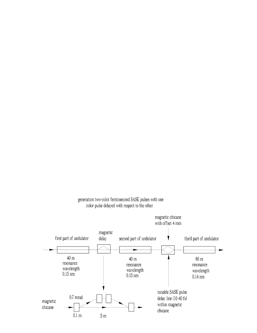
As we will discuss in Section 4, our method can also be used in the case of long-pulse mode of operation. In fact, there is no principle difference between long-pulse and short-pulse modes of operation concerning our pump-probe technique. However, in the case of short-pulse mode of operation, described in the next Section 2, the hardware requirement is minimal, and through this paper we will mainly focus on this case. For its implementation it is sufficient to substitute a single undulator segment with a short magnetic chicane, Fig. 4, whose function is both, to wash out the electron bunch microbunching, and to delay the electron bunch with respect to the x-ray pulse produced, in the linear regime, in the first part of the undulator. In this way, half of the electron bunch is seeded, and saturates in the second part of the undulator. Finally, the second half of the electron bunch, which remains unspoiled, lases in the third part of the undulator at a different wavelength.
2 Feasibility study

With a baseline gap-tunable undulator design (like in the SASE2 case) the pump-probe option in the short-pulse mode of operation only requires the installation of a magnetic delay. Thus, the hardware required for the implementation of our scheme is minimal, and consists in the substitution of one of the undulator segments with a magnetic chicane, as shown in Fig. 4. The quadrupole separation of the undulator FODO lattice ( m) is large enough so that a relatively short ( m) magnetic chicane can be installed (see Fig. 5).

The electron beam first goes through the first undulator as in the baseline design, producing SASE radiation in the linear regime. After the first undulator the electron beam is guided through the magnetic chicane. The trajectory of the electron beam in the chicane has the shape of an isosceles triangle with the base equal to the undulator segment length, . The angle adjacent to the base, , is considered to be small. The magnetic delay needed for the generation of two color x-ray pulses should satisfy three requirements.
First, the radiation pulse must overlap only half of the electron bunch at the chicane exit, i.e. the electron beam extra path length must be of the order of the rms of electron bunch length, as shown in Fig. 6. Second, collective effects, namely coherent synchrotron radiation (CSR) should be avoided in order to preserve transverse emittance. In the present case, simple estimations show that CSR should not be a serious limitation in our case. Third, the electron beam modulation introduced in the first undulator due to FEL interaction must be washed out. The presence of a local energy spread in the electron beam naturally solves the problem. In fact, for Gaussian local energy spread, and neglecting collective effects, the amplitude of the density modulation at the chicane exit is given by
| (3) |
where is the amplitude of the density modulation at the entrance of the chicane, is the momentum compaction factor and is the reduced wavelength. In our case, parameters of interest are the undulator segment length m, the deflection angle mrad, the dispersion m, and the relative energy spread , corresponding to an energy spread of about MeV. This leads to the suppression of the beam modulation by a factor of about . Here we assume that an uncorrelated relative energy spread of MeV is already present at the entrance of the SASE undulator.
One may also account for the linear energy chirp in the electron beam by introducing a resonance frequency-shift in the second undulator. Thus, we can neglect the linear energy chirp and account for the non-linear energy chirp only. We further require that the non-linear energy chirp be sufficiently small, and that the energy deviation across the lasing part of the bunch be smaller than the FEL parameter. In our case study , and simple estimations show that the energy chirp should not be a serious limitation.
After the chicane, the relative positions of radiation and electrons at the entrance of the second undulator part looks like on the right of Fig. 6. The left half of the bunch will start the usual SASE process form shot noise. The right half, instead, is seeded by the radiation produced in the first part of the undulator, and will reach saturation much sooner. Finally, a third undulator part, tuned at a slightly different frequency, will allow two-color operation: the right half of the bunch is spoiled by the SASE process and cannot radiate anymore, while the left half emits usual SASE radiation up to saturation. Low-charge bunch simulations are not time expensive, and we it find convenient to use the Genesis code GENE , i.e. the same code used for simulations at LCLS. In the following we describe the outcomes our of these computer simulations.
2.1 First stage


2.2 Magnetic delay
Following the first undulator part, one has to model the magnetic delay. This is accounted for by shifting on the right the output field from the first part of the undulator111For this particular simulation example, radiation was shifted right of m., thus simulating a relative delay of the electron bunch. The field distribution obtained in this way, which is fed into the simulations for the second undulator part, is shown in Fig. 9.

It should be noted that the energy modulation of the electron bunch is suppressed in the same degree as the density modulation (aside for a different pre-exponential factor). Therefore, we can conclude that the problem of suppressing the beam modulation induced in the first undulator is solved quite naturally due to the presence of energy spread in the electron beam222Here we assume a Gaussian uncorrelated energy spread at the entrance of the first undulator of about . This spread can be introduced simply by tuning the gap of the first modules of the first undulator to . In this way, the magnetic field is large enough to guarantee generation of the energy-spread level needed due to quantum diffusion.. As a result, the initial modulation of the electron beam at the entrance of the second undulator is given by shot noise only. It should also be remarked here that we use a relatively weak chicane for which the spread of the phase shift between electrons due to energy spread (magnetic delay is non isochronous) is a few wavelengths only. This is more than sufficient for suppressing (smearing) the short radiation-wavelength scale modulation into electron beam, but does not change the large FEL coherence-length scale modulation presented in Fig. 8.
2.3 Second stage
Together with the shifted radiation pulse, also an electron beam generated using the values of energy loss and energy spread at the exit of the first stage is fed in the simulation of the second undulator part. The second undulator part is taken to be another cells long. The output power distribution is shown in Fig. 10, while energy loss and energy spread are plotted in Fig. 11.


As one can see, the seeded part of the electron bunch reaches saturation with ten GW power level, of the order of the baseline operation mode (see Fig. 2). The left part of the electron bunch produces SASE radiation in the linear regime only, which is negligible. The correctness of these outcomes is also supported by inspection of Fig. 11 and comparison with Fig. 3. The fact that the right part of the electron bunch is spoiled is evident from such comparison. The left part of the electron bunch has effectively not lased yet, and can be further used in the third undulator part.
2.4 Third stage
The simulations for the third undulator part consist once more of SASE simulations, where the electron beam used is generated, as described in section 2.3, using the values of energy loss and energy spread at the end of the second undulator part. The resonant wavelength is now set, for exemplification purposes, to nm. Obviously, such choice is arbitrary333Within the tunability range of SASE2, and within the available length for the second stage ( m) it is possible to reach saturation at least within full range 0.1-0.4 nm.. The output power distribution after further undulator segments is shown in Fig. 12, while the energy loss and energy spread are plotted in Fig. 13.
There are still about m of undulator available after the end of the third stage, and in principle one may continue the SASE process beyond saturation, as shown in Fig. 14. However, we choose to have the end of the third part of the undulator coinciding with the output level of the second stage.
Inspection of Fig. 12 and Fig. 13 show that the electron beam is now spoiled by the SASE process, i.e. the fresh part of the bunch has lased.


2.5 Results
The overall result of our simulations is shown in Fig. 15. The output pulses from the second and the third part of the undulator are shown, together with the current profile of the electron bunch. Two femtosecond, ten GW level pulses of coherent x-rays with two different colors can be easily generated with this method.

3 Photon beam manipulation
3.1 Tunable relative delay
Once the result shown in Fig. 15 is established, one faces the task of transport and utilization of the two radiation pulses to the experimental station. While transport can be performed with the same optics without problems, utilization for pump-probe experiments implies the capability of separating and delaying the two pulses of a given temporal amount at the experimental station. Investigating this capability goes beyond the scope of this paper.

A possible alternative is to include a tunable delay already at the level of the SASE undulator setup. This can be done with usual grazing-incidence optics. The idea is to install a mirror chicane between the second and the third part of the undulator, as shown in Fig. 16 and Fig. 17. The function of the mirror chicane is to delay the nm-radiation relatively to the bunch and, therefore, also relatively to the nm-pulse. The glancing angle of x-ray mirrors is as small as mrad. Inside the photon-beam transport tunnel, the transverse size of the radiation requires long mirrors, in the meter size. In contrast to this, at the undulator location, the transverse size of the photon beam is smaller than m, meaning that the mirror length would be just about cm. Moreover, the short-pulse mode will relax the heat-loading issues.
Of course, in order to install the mirror chicane one needs to first create an offset for the electron trajectory, meaning that a magnetic chicane should be inserted at the position of the mirror-chicane. The mirror chicane can be built in such a way to obtain a delay of the SASE pulse of about fs. This is enough to compensate a bunch delay of about fs from the magnetic chicane, and to provide any desired temporal shift in the range fs, as shown in Fig. 16.
3.2 Separating the two-color pulses


It should be noted that the main difficulty concerning the manipulation of the two-color photon beam consists in the separation of the two colors. Once this task is performed, the delay problem can be easily solved in the experimental hall with the help of mirrors. Of course, the two colors can be separated in the experimental hall as well with the help of crystals. However, this would lead to a loss of photons due to narrow bandwidth of the crystals.
As an alternative to the tunable relative delay considered above, here we propose to separate the two colors already in the undulator with the help of x-ray mirrors. The idea is sketched in Fig. 18 and Fig. 19. The two colors can be separated horizontally by two mirrors installed within the chicane after the second undulator. The horizontal offset can be about mm, which is enough for separating the two-color pulses, because at the position of the optical station the FWHM beam size is less than a millimiter. Additionally, mirrors can also be used to generate a few rad deflection-angle, which is not important within the undulator but will create further separation of a few millimeters at the position of the experimental station.
4 Long-pulse operation mode


As mentioned in the introduction, our method is also suitable for the long-pulse operation mode. A straightforward way of application consists in increasing the magnetic chicane angle up to about mrad, thus providing a relative delay of the electron beam with respect to the electron pulse of fs.
Alternatively, one may use an optical delay line which would, however, require extra-hardware. A mirror chicane like that considered in section 3 would delay the radiation relatively to the bunch (see Fig. 20). The difference with respect to the optical chicane for obtaining a tunable delay, considered above, is that now the optical delay line should be installed between the first and the second undulator. As before, the combination optical delay-magnetic chicane can be built in such a way to obtain a delay of the SASE pulse relative to the electron beam of about fs, as shown in Fig. 22. In this way, the strength of the magnetic chicane can be reduced, and the deflection angle of the electron beam can be set to mrad. Also note that heat-loading problems would be strongly mitigated by the fact that the photon pulse is still in the linear regime, at low power ( MW).
5 Conclusions
We presented a method to obtain two short (sub-ten fs), powerful (ten GW-level) pulses of coherent x-ray radiation at different wavelengths for pump-probe experiments at XFELs. The idea is based on the fresh-bunch technique HUAYU , SAL1 , SAL2 , and can be realized based on the ideal performance of the beam formation system, which has been experimentally demonstrated at LCLS LCLS1 , LCLS2 .
The method relies on the substitution of a single undulator segment with a delay stage. In its simplest form, that can be implemented in the short-pulse operation mode demonstrated at LCLS DING , the delay stage is just constituted by a magnetic chicane. The method can also be implemented in the long-pulse operation mode, in which case an extra optical delay stage must be provided in the same undulator segment. Manipulation of a single segment returns great advantages, but it should be clear that our technique is actually based on the experimentally demonstrated availability of optimal full-scale facility parameters.
Since it is based on manipulation of a single segment, the method is at the same time low cost, and very robust. Also, it does not perturb the baseline long-pulse operation mode, and carries no risks for the operation of the machine. Finally, and most importantly, the two-color X-ray pulses are precisely synchronized at the femtosecond level, since they both are produced by the same electron bunch, and there is no time jitter between the pulses.
Our study is exemplified with parameters typical of the SASE2 line of the European XFEL. Nevertheless it can be applied at any XFEL facility.
6 Acknowledgements
We are grateful to Massimo Altarelli, Reinhard Brinkmann, Serguei Molodtsov and Edgar Weckert for their support and their interest during the compilation of this work.
References
- [1] J. Arthur et al. Linac Coherent Light Source (LCLS). Conceptual Design Report, SLAC-R593, Stanford (2002). See also http://www-ssrl.slac.stanford.edu/lcls/cdr.
- [2] P. Emma, First lasing of the LCLS X-ray FEL at 1.5 , in Proceedings of PAC09, Vancouver, to be published in http://accelconf.web.cern.ch/AccelConf/
- [3] Y. Ding et al., Phys. Rev. Lett. 102, 254801 (2009).
- [4] J. Feldhaus et al., NIM A 528, 453 (2004).
- [5] U. Frhling et al., Nature Photonics, 3, 523 (2009).
- [6] I. Ben-Zvi and L.H. Yu, Nucl. Instr. and Meth. A 393, 96 (1997).
- [7] E. Saldin, E. Schneidmiller and M. Yurkov, Opt. Commun. 212, 377 (2002).
- [8] E. Saldin, E. Schneidmiller and M. Yurkov, Opt. Commun., 239, 161 (2004).
- [9] M. Altarelli, et al. (Eds.) XFEL, The European X-ray Free-Electron Laser, Technical Design Report, DESY 2006-097, Hamburg (2006).
- [10] S Reiche et al., Nucl. Instr. and Meth. A 429, 243 (1999).