e-mail reinhard@theorie2.physik.uni-erlangen.de, Phone: +49-9131-85-28462, Fax: +49-9131-85-28907
2 Laboratoire de Physique Théorique, IRSAMC, UPS and CNRS, Université de Toulouse, 118 Rte de Narbonne, F-31062 Toulouse cedex, France
3 Department Chemie and Catalysis Research Center, Theoretische Chemie, Technische Universität München, D-85748 Garching, Germany
XXXX
Angular distributions of electrons emitted from free and deposited Na8 clusters
Abstract
We explore from a theoretical perspective angular distributions of electrons emitted from a Na8 cluster after excitation by a short laser pulse. The tool of the study is time-dependent density-functional theory (TDDFT) at the level of the local-density approximation (LDA) augmented by a self-interaction correction (SIC) to put emission properties in order. We consider free Na8 and Na8 deposited on the surfaces MgO(001) or Ar(001). For the case of free Na8, we distinguish between a hypothetical situation of known cluster orientation and a more realistic ensemble of orientations. We also consider the angular distributions for emission from separate single-electron levels.
pacs:
31.15.ee, 33.60.+q, 36.40.Vz, 36.90.+f, 68.47.Jn, 79.60.-i1 Introduction
Optical methods have provided the key analyzing tools in cluster physics over decades. In the first stage, optical absorption measurements allowed one to collect rich information on structure and dynamics of these small, nano-sized particles; for an overview see, e.g., [1, 2, 3, 4]. More information can be gathered when one additionally measures the features of reaction products in more detail. A most important channel in this context is electron emission and thus there meanwhile exist many investigations that analyze the properties of the electrons emitted after irradiation by a short laser pulse. The first step in that direction is photoelectron spectroscopy (PES) where the distribution of the kinetic energy of the emitted electrons is recorded. This method has been applied in cluster physics since long, see e.g. [5, 6]. Stepping further in refinement, one can determine the angular distribution of the outgoing electrons which, in fact, is mostly done simultaneously together with PES [7, 8, 9, 10, 11, 12]. Further challenging aspects come into play when considering clusters in contact with substrates. That combination is often motivated (if not dictated) by easier experimental handling. It is of great importance for possible practical applications, and the effects at interfaces are also an interesting problem for basic research, for up to date collections see e.g. [13, 14]. It is obvious that the deposition on a surface modifies the emission properties, in particular angular distributions, thus calling for dedicated theoretical studies. This paper is devoted to a theoretical exploration of angular distributions of laser excited metal clusters, free and deposited on insulating surfaces, MgO(001) and Ar(001).
There is a broad choice of approaches for the description of clusters on surfaces, from fully detailed quantum mechanical treatments of all constituents [15] to a robust jellium treatment of cluster and interface [16]. We are going here for an intermediate strategy, detailed at the side of the highly reactive cluster and less so for the inert substrate. As a basis of the description, we employ density-functional theory [17], which provides a most efficient theoretical description for the electronic structure and dynamics of clusters [18]. We simulate the detailed dynamics of laser excitation and subsequent electron emission by time-dependent density-functional theory (TDDFT) solved on a grid in coordinate space. The substrates are inert and will be described classically in terms of polarizable atoms [19, 20]. The computation of angular distributions requires rather large numerical boxes. Therefore, previous explorations dealt with approximations, a semi-classical approach [21] which is confined to very intense laser pulse or a quantum-mechanical, but two-dimensional axial, treatment [22, 23] for lower intensities and short pulses. Here we are going for a fully three dimensional TDDFT analysis because both simplifications are not applicable anymore for the studies intended here and because the progress of computational resources meanwhile allows a TDDFT analysis in full three spatial dimensions. We will take Na8 as a test case and compare free Na8 with Na8 on MgO(001) as well as Na8 on Ar(001).
The study concentrates on direct electron emission, i.e. those electrons which are leaving the cluster with or directly after laser impact. In practice, there is a competition between direct and thermal emission. The preferred exit channel depends on the length of the laser pulse. For pulses longer than the collisional relaxation time induced by two-electron processes, thermal emission dominates, while shorter pulses change the weight towards direct emission [24, 25, 26, 27]. We will use here pulses with full width at half maximum of 20 fs, which surely are at the side of dominant direct emission.
There is also a subtle point about the orientation of the cluster relative to the laser polarization. Experiments with clusters in the gas phase deal, in fact, with an equi-distributed ensemble of orientations, while deposited clusters have a well defined orientation due to the known surface structure. We will briefly address this question, considering both free clusters with known orientation and averaging over cluster orientations. We will then return to oriented clusters and investigate the changes caused by deposition on a surface. We will discuss how the specific angular distributions for emission of each single-electron state separately combine to the total distributions and how this helps to understand the pattern observed in emission from deposited clusters. Furthermore, we will investigate and compare two different substrates, MgO(001) and Ar(001) surfaces. Both are insulators with a rather large band gap. The MgO(001) surface shows more corrugation and has a stronger interface attraction, while Ar(001) is softer and dominated by core repulsion.
The paper is outlined as follows. In section 2, we briefly summarize the formal framework, numerical strategies, and the basic properties of the test cases. In section 3, we present and discuss results on free Na8 and also explore the double differential distributions. Section 4 compares results for free Na8 to those for Na8 deposited on MgO(001) and Ar(001). Conclusions are given in section 5.
2 Brief summary of the model
2.1 The degrees of freedom
The hierarchical quantum-mechanical-molecular-mechanical (QM/MM) model has been described in detail elsewhere (see [20, 28] and [29] for a recent detailed review). Here we give a brief outline. The constituents of the system and their degrees of freedom are: for valence electrons of the Na cluster, for the positions of the Na+ ions, for the positions of the O cores, for the centers of the O valence clouds, for the positions of the Mg2+ ions. The Na cluster is treated in standard fashion: The valence electrons quantum-mechanically and the ions classically [18, 30]. The MgO substrate is composed of two species : Mg2+ cations and O2- anions. The cations are electrically inert and can be treated as charged point particles; they are labeled by . The anions are easily polarizable; this fact is accounted for by associating them with two constituents : A valence electron distribution (labeled by ) and the complementing core (labeled by ). All ions of the MgO substrate are described as classical degrees of freedom in terms of positions . The difference describes the electrical dipole moment of an O2- anion. The Mg and O ions are arranged in crystalline order corresponding to bulk MgO. The dynamical degrees of freedom for Mg and O are taken into account in an active cell of the MgO(001) surface region underneath the Na cluster. The active cell is embedded in an “outer region” of MgO material where only ions are kept fixed, while oxygen dipoles remain fully dynamical. Beyond that region, only the Madelung potential is considered. The effect of the outer region on the active part is given by a time-independent shell-model potential taken over from [31]. Actually, the substrate consists of six layers each containing 784 Mg2+ ions and 784 O2- ions. The ions in the lowest layer are fixed to prevent them from relaxing and forming an artificial second surface. The active cell consists of three layers, each containing square arrangements of 242 Mg2+ cations and 242 O2- anions.
In the case of Ar, the modeling follows a similar, although simplified, track [19, 32]. The Ar substrate is composed of only once species, neutral Ar atoms, each of which being characterized by its position and dipole moment (exactly as O2- anions). The substrate comprises 384 atoms; this model has been shown to provide a fair approximation to bulk [33, 34].
2.2 Energy and fields
The total energy is decomposed as where describes an isolated Na cluster, the MgO(001) or Ar (001) substrate, and the coupling between the two subsystems. For , we take the standard functional of TDDFT at the level of the local density approximation (LDA), coupled with molecular dynamics (MD), as in previous studies of free clusters [18, 30] including an average density self-interaction correction [35]. The energy of the substrate and the coupling to the Na cluster consists of the long-range Coulomb energy and some short-range repulsion which is modeled through effective local core-potentials [31, 36, 37]. To avoid the Coulomb singularity and to simulate the finite extension of Ar, Mg2+ and O2- ions, we associate a smooth charge distribution with each of these ionic centers. This yields a soft Coulomb potential to be used for all active particles. The model parameters were calibrated to represent results of calculations where a fully quantum-mechanical description of the active MgO cell was employed in the case of MgO, for details see [20]. The model parameters for the Ar substrate were chosen to reproduce model calculations of the NaAr dimer [38], in turn fitted to ab-initio data.
The field equations obtained by variation of the above energy are augmented by the external laser field
| (1) |
which is activated only in the time interval . The field strength is related to the intensity as . The total pulse length corresponds to a full width at half (intensity) maximum as FWHM. The laser polarization can take any direction. We will consider , the direction perpendicular to the surface, i.e. along the symmetry axis of Na8, and one direction orthogonal to it with (for the geometry, see section 2.5). A laser with polarization is, of course, an idealization because it would correspond to a plane wave running parallel to the surface, but it serves to model rather flat impact as compared to the perpendicular impact of -polarization.
From the energy functional, once established, one derives the static and dynamical equations variationally in a standard manner [18].
2.3 Solution scheme
The numerical solution of the coupled quantum-classical system proceeds as described in [20, 19, 39]. The electronic wave functions and the spatial fields are represented on a Cartesian grid in three-dimensional coordinate space. The numerical box employed here has a size of . The spatial derivatives are evaluated via fast Fourier transformation. The ground state configurations were found by accelerated gradient iterations for the electronic wave functions [40] and simulated annealing for the ions in the cluster and the substrate. Propagation is done by the time-splitting method for the electronic wave functions [41] and by the velocity Verlet algorithm for the classical coordinates of Na+ ions and MgO or Ar constituents.
2.4 Gathering angular distributions
Electrons emitted from the cluster will eventually arrive at the boundaries of the box. In order to suppress re-feed of these electrons back into the box, we employ absorbing boundary conditions [30, 42]. This is achieved by the mask function defined as :
| (2a) | |||
| where is the cut-off radius outside which absorption starts and is the minimal radial distance from the origin to the closest point on the boundaries. The Kohn-Sham time step actually performed with the time-splitting method [41] is thus augmented by an absorbing step as | |||
| (2b) | |||
where is the unitary propagation operator. Applying the mask function to the orbitals gently removes density approaching the box boundary and prevents it from being reflected.
To compute the angular distribution of emitted electrons, the absorbed density is accumulated for each state and each (absorbing) grid point as
| (3a) | |||||
| By definition of , the field is non-vanishing only in the spherical absorbing zone. The angular distribution of emitted electrons is finally gathered by dividing the absorbing zone into radial segments , and integrating over those segments. The Photoelectron Angular Distribution (PAD) then becomes | |||||
| (3b) | |||||
| (3c) | |||||
where denotes the area of the segment on the surface of a unit sphere. Eq. (3c) provides the total cross-section, while Eq. (3b) the cross-section for emission from a specific quantum state .
We will sometimes present simpler polar distributions, averaging the full distributions over and dividing by the polar volume element (see Figure 1). This is convenient when the variation in is weak. However, even if the azimuthal distribution may carry interesting details, particularly for deposited clusters, we will see that the reduced view can bring some useful information.
It is to be noted that we consider here PAD which are integrated over all outgoing electron momenta. The state-specific PAD carry automatically some information on the electron spectra because the dominant emission strength goes into the first (multi-)photon peak above continuum threshold. More detailed information can be gathered with techniques as proposed in [22, 43]. They also allow to produce a double differential cross-section providing the photo-electron spectra in each angular bin separately. An explanation of this technique and the much more complex analysis of the emerging data is postponed to a later publication.
2.5 Structure of the test cases
As test cases, we will consider the free Na8 cluster and Na8 deposited on MgO(001) or Ar(001) surfaces. Starting point of the laser-induced dynamics is a well relaxed structure of each system. These structures had been discussed extensively in [20].
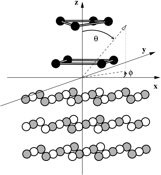
Figure 1 illustrates the structure of Na8 on MgO(001). The symmetry axis of Na8 which coincides for the deposited Na8 with the axis perpendicular to the surface is taken as -axis. The MgO surface is a cut from the cubic crystal structure. On the surface, the O and Mg ions are arranged in squares where next neighbors are always the other species.
The Na8 cluster has a highly symmetric configuration out of two rings of four ions each, twisted relative to each other by 45∘ to minimize the Coulomb energy. The Na8 is rather rigid and only very little affected by the surface. Free Na8 is very similar to the deposited cluster shown here, with bond lengths differing by less than 3%. The same holds for Na8 on Ar(001).
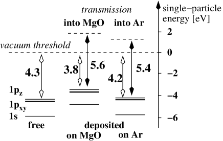
The electronic cloud of free Na8 exhibits close to spherical shape because electrons corresponds to a strong electronic shell closure for Na clusters [44]. That changes for the deposited cluster. The surface destroys the reflection symmetry which, in turn, mixes single-electron states of different -parities. The presence of the surface does also shift the single-electron levels and the ionization potentials (IP). The relations are sketched in figure 2. The IP is eV for free Na8, eV for Na8 on MgO(001) and eV on Ar(001). The transmission barrier for emission from deposited Na8 into the substrate lies at eV for MgO(001) and eV for Ar(001): both are substantially larger than the IP. The and levels of free Na8 are perfectly degenerate, slightly split from due to a very small quadrupole deformation of Na8. The ionic structure of Na8 deposited on MgO(001) hardly changes because the magic electron configuration renders that cluster very rigid. There is an overall up-shift due to core repulsion from MgO. The symmetry breaking due to the surface orientation slightly splits the levels, by 0.204 eV. Much less shifts are seen for Na8 on Ar(001) and the splitting between and , 0.05 eV, is also much smaller. That difference correlates to the much lower interface energy of the Na-Ar system. Indeed, the bottom layer of Na8 is within 5.1 from the MgO(001) surface, much closer to the substrate than in the case of Ar(001) (6.4 ).

The optical absorption spectrum of our test cases is shown in figure 3.One recognizes the pronounced Mie surface plasmon resonance [1, 3, 18]. For free Na8, there is one clean peak at 2.45 eV almost the same for each mode. The surfaces lead to some spectral fragmentation, about 1.4 eV for MgO(001) and 0.2 eV for Ar(001). The highly polarizable MgO(001) also induces a small down-shift of the resonance center to 2.31 eV while core repulsion outweighs polarization for Ar(001) leading to a small up-shift to 2.54 eV. The MgO(001) surface leads to a strong fragmentation of the mode essentially due to symmetry breaking [20].
In the following studies, we will vary laser frequency and polarization. We work in all cases with the same pulse length fs, which corresponds to FWHM fs. The angular distributions in the high-intensity regime are always concentrated on forward and backward emission along the laser polarization axis, whereas a high sensitivity to all details of the excitation is found in the regime of weak perturbations [23]. The present study thus aims at staying close to the perturbative regime to explore the rich variety of distributions. The intensity should be low enough for a perturbative regime being valid [22, 26, 45], but also sufficiently high to provide signals safely above numerical noise. We found an intensity of W/cm2 to be a good compromise and we used that value in most of the test cases. Use of a different value will be clearly indicated.
3 Brief survey of free Na8
Detailed studies of the PAD of free clusters will be discussed in a forthcoming publication. We briefly summarize here the results.
Variation of the laser intensity shows almost constant pattern of the PAD throughout the regime of moderate intensities. For further increasing intensities, the structures change steadily towards simple forward-backward scattering. This is related to the transition from the frequency-dominated regime of moderate intensities to the field dominated highly non-linear regime [27, 30, 46, 47].
Variation of frequency leads to dramatic changes in the angular distributions.
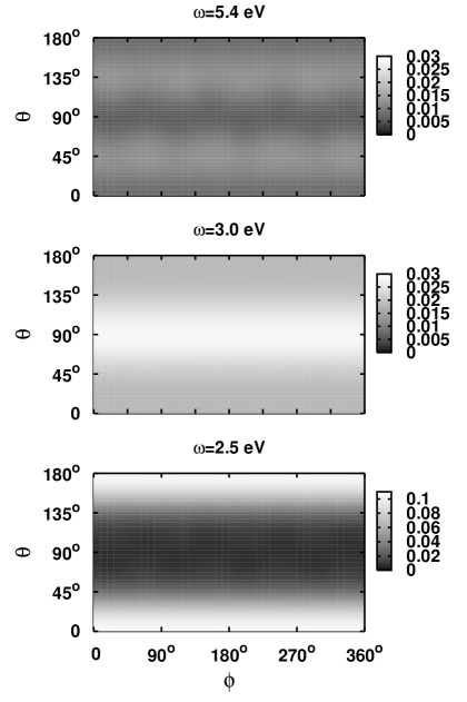
They vary amongst three typical patterns. We have chosen three frequencies to have an example for each type. Results are shown in figure 4. The most common case is forward scattering (along the axis of polarization, ), seen here in the lowest panel for eV. Sometimes one encounters “diagonal scattering” where electron emission is concentrated on a double cone around angle (with respect of the -axis), see upper panel for eV. Sideward scattering as exemplified in the middle panel, is observed occasionally, here for eV. Note that the spectral relations of these three cases are very different. For 5.4 eV, we have a one-photon process for the states but a (much suppressed) two-photon process from the state. For 3 eV, we have a two-photon process for both, the and the shell. And for 2.5 eV, we have a two-photon emission from the while the shell, again, requires one more photon.
The strong frequency dependence of the PADs can be related to the fact that the strongest emitting single-electron state depends sensitively on the relationship between laser frequency and IP, and that the emission from each state looks very differently. This is demonstrated by analyzing the PADs of individual single-electron states. Experimentally, this is achieved by measuring the PAD simultaneously with the photoelectron spectrum (PES) [8, 10, 48]. The energy selection by PES allows one to associate the PAD to the single-electron states from which these were produced. Theoretical calculations have the separate information trivially at hand, as seen in Eq. (3c).
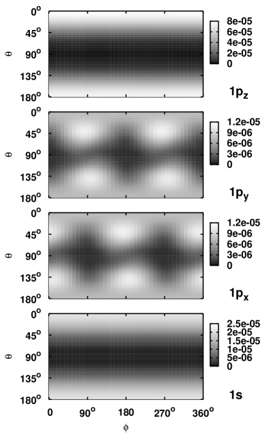
Figure 5 shows the state-specific PAD of free Na8 for the (hypothetical) case that the clusters symmetry axis is aligned with the laser polarization. The separate distributions are much more structured and show their maxima at different angles. Particularly noteworthy are the pattern from the and states. Both have their emission maxima at polar angle and and both show pronounced structures in azimuthal angle ; the azimuthal pattern is shifted by between and . That feature will play a role again for deposited Na8, see section 4. The maxima at and can be qualitatively understood in a picture using wave functions of a spherical mean field. The have then the angular wave function in terms of the spherical harmonics . The dipole excitation comes with angular distribution . For , the emitted wave is driven by the product , having maxima at and , and for by with maxima at and , while both waves are maximized at and . This picture agrees with the obtained patterns in figure 5. Note that the total cross-section of free Na8 does not exhibit any structure in as the and distributions add up to a constant value in (besides a faint perturbation by the ions). A similar finding holds for the energy-resolved distributions as the states and have exactly the same single-electron energy and thus are added up with equal weight. We also separately explored the frequency dependence of the distributions for emission from each single-electron state. They turned out to depend much less on the frequency than the total PAD. We refrain from presenting these results in detail as this would require quite a bit space.

Considering free clusters with known orientation allows one to investigate characteristic structural features and to provide basic information for deposited clusters to be discussed later on. An alignment of clusters in the gas phase remains an open experimental problem (“orientation burning” may be an option [49]). Present-days experiments in the gas phase measure an ensemble of clusters where all orientations are equally distributed. A simulation of that situation requires one to calculate an ensemble of orientations and to average the emerging angular distributions. The procedure is straightforward. We computed angular distributions on a grid of orientations with grid spacing of 22.5∘ in Euler angles and , ignoring due to the near axial symmetry of Na8, and added them with appropriate geometrical weights. The orientation averaging wipes out the sub-structures along direction. Figure 6 shows the resulting (orientation averaged) distributions along polar angle . Note that we have also averaged over and distributions since these two states are energetically degenerate and could not be discriminated by PES. The orientation averaging yields much different and simpler structures than those seen in the case of known orientation, see figure 5. The dominance of purely forward-backward structure holds only for the small system Na8. Larger clusters show richer structures [10, 50, 51].
4 Emission patterns for deposited Na8
4.1 Deposition on MgO(001)
As pointed out in section 3, the detailed analysis of free PAD leads to remarkable insights into the structures of clusters. However, the orientation problem inherent to clusters in the gas phase blurs some of the detailed information. It is thus interesting to consider the complementing case of deposited clusters where the orientation is well defined. On the other hand, the presence of the substrate complicates the PAD. Analysis of this effect is thus a key issue.
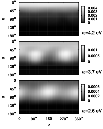
Figure 7 displays angular distributions of Na8 on MgO(001) for three different frequencies. Again, the frequencies were selected to show three different and typical emission patterns. The sequence is comparable to the case of free Na8 discussed above, but having somewhat lower values to accommodate for the lower IP (see figure 2) and stay below the transmission threshold. The substrate obviously has a very strong influence such that the patterns are quite different from those of free Na8. The dominant forward emission () is still observed; backward emission () is, of course, totally suppressed by the presence of the insulating substrate. More surprising is the appearance of a strong azimuthal dependence. Recall the pronounced azimuthal structures for emission from the levels of free (aligned) clusters, see figure 5. In the total or energy-resolved cross-sections of free clusters, these structures are wiped out by the degeneracy, as each of the two levels contributes equally to the emission strength, see the discussion of figure 5. This – degeneracy is now split by the surface leading to an energy difference between and state of 0.2 eV. Because these states are close to the emission threshold, the small energy difference has a large effect on the relative emission strengths. One of the two states dominates emission and its pattern affects the total distribution. Comparison to figure 5 makes it clear that the dominant state is for eV (figure 7, lower panel) and for eV (figure 7, middle panel). There is also some effect on the polar distribution. The emission cones are neither perfectly aligned along , as in a sidewards emitting case, nor along , as was the case for orbitals of free Na8. The composition of emission strengths from the four single electron levels is different for the deposited case as compared to free Na8. Furthermore, the polarization attraction bends the outwards cones towards the substrate. Both effects together widen the emission cone such that the angle of inclination of the emitted electrons relative to the surface decreases.
This example demonstrates that the detailed structure of the angular distribution, in the polar as well as in the azimuthal angles, sensitively depends on the laser frequency. There is much more structure compared to the emission spectra of free clusters, thus more information, worth to be unraveled. That information, however, is masked by the involved interplay of cluster and surface which inhibits simple one-to-one correspondences and requires a careful correlation analysis.
4.2 Comparison with argon substrate
We also investigated the case for another combination, namely Na8 on Ar(001). Frozen Ar is an insulator as MgO is. We thus expected, as in the case of Na8 on MgO(001), heavily modified angular distributions compared with the free Na8 case. Ar is, however, a Van-der-Waals bound system with a smaller surface corrugation and smaller initial polarization fields, in contrast to the ionic crystal MgO.
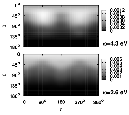
Figure 8 shows angular distributions for Na8 on Ar(001) at two frequencies of the laser field. The effects are very similar to the case of MgO. Backward scattering is totally suppressed, forward scattering is accordingly enhanced, there appear pronounced azimuthal structures, and the distributions depend sensitively on the frequency. With , the splitting of the 1 levels due to Ar(001) surface is similar to that at MgO, which is probably responsible for the similarities of the emission patterns between Ar and MgO. There is, however, one difference to the case of MgO. The sideward cone (lower panel of figure 8) is not so close to the surface and points towards a polar angle of as in the case of free Na8. That is probably due to the smaller surface polarization for Ar.
4.3 Frequency and intensity dependences
In this section we explore more systematically the influence of laser frequency and intensity on the angular distributions for deposited Na8. To simplify the graphical representation, we consider -averaged distribution along polar angle .

Figure 9 shows azimuthally averaged distributions for emission from Na8 on MgO(001). The upper panel presents the variation with for moderate intensity. The prevailing effect is the strong suppression of backward emission through the substrate. In spite of reflection-enhanced surface dominance, we see again the variation of pattern with frequency qualitatively similar to the case of free Na8 (see figure 4). The pattern is, however, more involved than what would emerge from a simple rescattering of the reflected electrons to angle . The surface attraction shifts the former diagonal maximum from towards the substrate and produces sizeable emission under rather flat angles . A first glimpse of transmission into the substrate can be seen for eV. That is very close to the transmission threshold for Na8 on Mg(001) at about 5.58 eV, see figure 2.
The lower panel of figure 9 shows the changes with increasing intensity for fixed frequency. We see again the expected typical increasing focus towards forward emission. A somewhat surprising and most interesting effect is that backward emission gathers rather large strength with further increasing intensity. The high field strengths make two- and more-photon processes competitive which, in turn overrules the frequency counting. However, one has to be cautious with interpreting these processes where substantial amounts of electron charge are penetrating into the substrate. The present QM/MM model is not set up for that situation and likely is no longer accurate at a quantitative level.

Figure 10 shows some azimuthally averaged distributions for Na8 on Ar(001). The general trends are very similar to the case of MgO, see for example the upper panel of figure 9. We see again the strong forward dominance due to reflection from the substrate and the strong dependence of the distribution on laser frequency as was observed before for all cases. There is a minor difference in that the chances for transmission into the substrate are even slightly lower.
5 Conclusion
We have explored from a theoretical perspective angular distributions of electrons emitted from Na8 clusters, free and deposited on Ar(001) or MgO(001) surfaces. Thereby we concentrated on direct electron emission which takes place within few fs after laser excitation and which is the dominant process for short laser pulses (up to about 50 fs). Several laser frequencies were used, higher ones above the threshold for one-photon emission, lower frequencies in the two-photon regime close to the Mie plasmon resonance, and cases safely off-resonance. The laser intensity was in most cases W/cm2, large enough to overcome numerical noise, but safely below the regime of violent and highly non-linear processes. The numerical simulations employed a hierarchical quantum-mechanical-molecular-mechanical (QM/MM) model approach. The cluster electrons were described by time-dependent density-functional theory (TDDFT) at the level of the local-density approximation (LDA). A self-interaction correction has been added to put the single-electron levels to the appropriate energy relative to the particle continuum. The cluster ions were propagated by classical molecular dynamics. Similarly, the Ar(001) or MgO(001) substrates were treated as classical systems with atomic positions and dipole polarizability as dynamical degrees of freedom. The TDDFT equations were solved on a three-dimensional coordinate-space grid without any symmetry restriction. Absorbing boundaries were applied and the angular distributions were obtained by recording the electron absorption at each grid point in the absorbing zone.
We first briefly explored free Na8. The state-specific distributions for Na8 aligned with laser polarization show pronounced patterns in both angles, and , which exhibit clear footprints of the emitting state. Simulating the experimental situation which deals with orientation averaged ensembles renders the distributions independent of the azimuthal angle and reduces structures in the polar angles . A study of averaging effects, size-, frequency-, and intensity-dependence for free clusters will follow in an upcoming publication.
The present study focused on angular distributions from Na8 deposited on MgO(001) and Ar(001). The attachment to the surface provides a well defined cluster orientation and it adds substantial perturbations from the surface interaction. The large band gaps of both materials manifested in high transmission barriers, almost totally suppress backward emission, focusing electrons into a forward cone. On the other hand, the long-range polarization attraction can bend sideward flowing electrons down towards the surface, thus widening the opening angle of the emission cone. Polarization is strong for MgO(001) which induces a sizeable trend to emission parallel to the surface. Repulsion dominates for Ar(001) which stabilizes the forward cone. The surfaces do also break the fourfold symmetry () of Na8 which, in turn, removes the degeneracy of the two single-electron levels with nodes orthogonal to the symmetry axis, and thus inhibits the compensation of dependence which was observed for (oriented) free Na8. Pronounced azimuthal structures are found for the distributions of the deposited cases.
Altogether, the computational study revealed interesting structures which are, however, somewhat complicated by surface (particularly the electronic and geometric structure of the clusters) contained in the calculated photoelectron angular distributions and their energy dependence.
This work was supported by the Deutsche Forschungsgemeinschaft (RE 322/10, RO 293/27), Fonds der Chemischen Industrie (Germany), a Bessel-Humboldt prize, and a Gay-Lussac prize.
References
- [1] M. Brack, Rev. Mod. Phys 65, 677 (1993).
- [2] W. A. de Heer, Rev. Mod. Phys. 65, 611 (1993).
- [3] U. Kreibig and M. Vollmer, Optical Properties of Metal Clusters (Springer Series in Materials Science, vol 25, 1993).
- [4] H. Haberland (ed.), Clusters of Atoms and Molecules 1- Theory, Experiment, and Clusters of Atoms (Springer Series in Chemical Physics, vol 52, Berlin, 1994).
- [5] K. M. McHugh, J. G. Eaton, G. H. Lee, H. W. Sarkas, L. H. Kidder, J. T. Snodgrass, M. R. Manaa, and K. H. Bowen, J. Chem. Phys. 91, 3792 (1989).
- [6] D. L. Lichtenberger, K. W. Nebesny, C. D. Ray, D. R. Huffman, and L. D. Lamb, Chem. Phys. Lett. 176, 203 (1991).
- [7] J. Pinaré, B. Baguenard, C. Bordas, and M. Broyer, Eur. Phys. J. D 9, 21–24 (1999).
- [8] B. Baguenard, J. C. Pinar, C. Bordas, and M. Broyer, Phys. Rev. A 63, 023204 (2001).
- [9] J. R. R. Verlet, A. E. Bragg, A. Kammrath, O. Cheshnovsky, and D. M. Neumark, J. Chem. Phys. 121, 10015–10025 (2004).
- [10] O. Kostko, C. Bartels, J. Schwobel, C. Hock, and B. von Issendorff, J. Phys. : Conf. Ser. 88, 012034 (2007).
- [11] S. Skruszewicz, J. Passig, A. Przystawik, J. Tiggesbäumker, and K. H. Meiwes-Broer, to be published (2009).
- [12] C. Bartels, C. Hok, J. Huwer, R. Kuhnen, J. Schwöbel, and B. von Issendorff, Science 323, 132 (2009).
- [13] K. H. Meiwes-Broer (ed.), Metal clusters at surfaces (Springer, Berlin, 2000).
- [14] K. H. Meiwes-Broer (ed.), Clusters at Surfaces: Electronic Properties and Magnetism (Applied Phys. A 82, special issue, 2006).
- [15] M. Moseler, H. Häkkinen, and U. Landman, Phys. Rev. Lett. 89, 176103 (2002).
- [16] V. V. Semenikhina, A. G. Lyalin, A. V. Solov‘yov, and W. Greiner, JETP 106, 678 (2008).
- [17] R. M. Dreizler and E. K. U. Gross, Density Functional Theory: An Approach to the Quantum Many-Body Problem (Springer-Verlag, Berlin, 1990).
- [18] P. G. Reinhard and E. Suraud, Introduction to Cluster Dynamics (Wiley, New York, 2003).
- [19] F. Fehrer, P. G. Reinhard, E. Suraud, E. Giglio, B. Gervais, and A. Ipatov, Appl. Phys. A 82, 151 (2005).
- [20] M. Bär, L. V. Moskaleva, M. Winkler, P. G. Reinhard, N. Rösch, and E. Suraud, Eur. Phys. J. D 45, 507 (2007).
- [21] E. Giglio, P. G. Reinhard, and E. Suraud, Phys. Rev. A 67, 43202 (2003).
- [22] A. Pohl, PhD thesis, Friedrich-Alexander-Universität, Erlangen/Nürnberg, 2003.
- [23] A. Pohl, P. G. Reinhard, and E. Suraud, Phys. Rev. A 70, 023202 (2004).
- [24] E. E. B. Campbell, K. Hansen, K. Hoffmann, G. Korn, M. Tchaplyguine, M. Wittmann, and I. V. Hertel, Phys. Rev. Lett. 84, 2128 (2000).
- [25] R. Schlipper, R. Kusche, B. von Issendorff, and H. Haberland, Appl. Phys. A 72, 255 (2001).
- [26] A. Pohl, P. G. Reinhard, and E. Suraud, J. Phys. B 37, 3301 (2004).
- [27] T. Fennel, K. H. Meiwes-Broer, J. Tiggesbäumker, P. M. Dinh, P. G. Reinhard, and E. Suraud, Rev. Mod. Phys., in press (2010).
- [28] M. Bär, PhD thesis, Friedrich-Alexander-Universität, Erlangen/Nürnberg, 2008.
- [29] P. M. Dinh, P. G. Reinhard, and E. Suraud, Phys. Rep., in press (2009), http://arxiv.org/abs/0903.1004v1.
- [30] F. Calvayrac, P. G. Reinhard, E. Suraud, and C. A. Ullrich, Phys. Rep. 337, 493 (2000).
- [31] V. A. Nasluzov, K. Neyman, U. Birkenheuer, and N. Rösch, J. Chem. Phys. 115, 17 (2001).
- [32] F. Fehrer, M. Mundt, P. G. Reinhard, and E. Suraud, Ann. Phys. (Leipzig) 14, 411 (2005).
- [33] P. M. Dinh, F. Fehrer, P. G. Reinhard, and E. Suraud, Eur. Phys. J. D 45, 415 (2007).
- [34] P. M. Dinh, F. Fehrer, P. G. Reinhard, and E. Suraud, Surf. Sci. 602, 2699 (2008).
- [35] C. Legrand, E. Suraud, and P. G. Reinhard, J. Phys. B 35, 1115 (2002).
- [36] G. R. Ahmadi, J. Almlöf, and J. Roegen, Chem. Phys. 199, 33 (1995).
- [37] F. Duplàa and F. Spiegelmann, J. Chem. Phys. 105, 1492 (1996).
- [38] M. Gross and F. Spiegelmann, J. Chem. Phys. 108, 4148 (1998).
- [39] F. Fehrer, P. G. Reinhard, and E. Suraud, Appl. Phys. A 82, 145 (2005).
- [40] V. Blum, G. Lauritsch, J. A. Maruhn, and P. G. Reinhard, J. Comp. Phys 100, 364 (1992).
- [41] M. D. Feit, J. A. Fleck, and A. Steiger, J. Comp. Phys. 47, 412 (1982).
- [42] C. A. Ullrich, J. Mol. Struct. (THEOCHEM) 501-502, 315 (2000).
- [43] A. Pohl, P. G. Reinhard, and E. Suraud, Phys. Rev. Lett. 84, 5090 (2000).
- [44] S. Bjornholm and J. Borggreen, Phil. Mag. 79, 1321 (1999).
- [45] F. H. M. Faisal, Theory of Multiphoton Processes (Plenum Press, New York, 1987).
- [46] P. G. Reinhard, F. Calvayrac, C. Kohl, S. Kümmel, E. Suraud, C. A. Ullrich, and M. Brack, Eur. Phys. J. D 9, 111 (1999).
- [47] G. Zwicknagel, C. Toepffer, and P. G. Reinhard, Phys. Rep. 309, 117 (1999).
- [48] O. Kostko, B. Huber, M. Moseler, and B. von Issendorff, Phys. Rev. Lett. 98, 043401 (2007).
- [49] P. G. Reinhard and E. Suraud, Eur. Phys. J. D 34, 145 (2005).
- [50] M. Baer, P. M. Dinh, L. V. Moskaleva, P. G. Reinhard, N. Rösch, and E. Suraud (2009), in preparation.
- [51] C. Bartels, PhD thesis, Albert-Ludwigs-Universität, Freiburg im Breisgau, 2008.