New Insights into Dissipation in the Electron Layer During Magnetic Reconnection
Abstract
Detailed comparisons are reported between laboratory observations of electron-scale dissipation layers near a reconnecting X-line and direct two-dimensional full-particle simulations. Many experimental features of the electron layers, such as insensitivity to the ion mass, are reproduced by the simulations; the layer thickness, however, is about times larger than the predictions. Consequently, the leading candidate 2D mechanism based on collisionless electron nongyrotropic pressure is insufficient to explain the observed reconnection rates. These results suggest that, in addition to the residual collisions, 3D effects play an important role in electron-scale dissipation during fast reconnection.
JI ET AL. \titlerunningheadElectron Dissipation in Reconnection \authoraddrH. Ji, Princeton Plasma Physics Laboratory, Princeton, NJ 08543, USA. (hji@pppl.gov)
Despite the disruptive influences of magnetic reconnection on large-scale structures in plasmas, the crucial topological changes and their associated dissipation take place only within thin current layers. The classical collisional models, where electrons and ions flow together through a single thin and long layer, fail to explain the observed fast reconnection rates. Modern collisionless models predict (Sonnerup, 1979; Mandt et al., 1994; Birn et al., 2001) that ions exhaust through a thick, ion-scale layer while mobile electrons flow through a thin, electron-scale layer, allowing for efficient release of magnetic energy. These ion layers have been frequently detected in space (e.g. Deng and Matsumoto, 2001; Øieroset et al., 2001; Mozer et al., 2002) and studied in detail in the laboratory (Ren et al., 2005; Yamada et al., 2006; Brown et al., 2006). In contrast, the electron layers, where magnetic field dissipates, are rarely encountered in space and are often detected at places far from the reconnection X-line line (Scudder et al., 2002; Mozer, 2005; Wygant et al., 2005; Phan et al., 2007). Therefore, whether the electron layers indeed exist near the X-line, and if yes, whether their associated dissipation results predominantly from laminar two-dimensional (2D) or three-dimensional (3D) dynamics as suggested by Xiao et al. (2006, 2007), is still an open question. Here we report detailed comparisons between recent laboratory observations of the electron layers near the X-line (Ren et al., 2008) and direct full-particle simulations in 2D. The measured electron layers display properties strikingly similar to predictions by 2D particle simulations, including their geometrical shape, insensitivity to ion mass, and sensitivity to the boundary conditions, but disagree on the electron layer thickness. As a consequence, the leading 2D mechanism based on collisionless electron nongyrotropic pressure is shown to be largely insufficient to explain the observed reconnection rates. These results suggest that, in addition to the residual Coulomb collisions, 3D effects play an important role in electron-scale dissipation during fast reconnection.
The laboratory measurements were performed on the well controlled and diagnosed experiment, Magnetic Reconnection Experiment (MRX) (Yamada et al., 1997), as illustrated in Fig.1. A pair of coil assemblies, known as flux-cores, are used to axisymmetrically initiate and maintain the reconnection process. Plasma is made by ionizing a pre-filled gas through pulsing toroidal field coil current within the flux-cores during the period when the current flowing in the poloidal field (PF) coils peaks. When the PF coil current is ramped down after the plasma is made, the field lines wrapped around both flux-cores are “pulled” back, reconnect, and move towards the flux-cores. Most of the important quantities can be either directly determined or indirectly inferred from these measurements in cylinderical coordinates () assuming axisymmetry: poloidal flux where is the reconnecting field; the toroidal reconnection electric field ; and the toroidal current density . The density and electron temperature are measured by a triple Langmuir probe and the flow speeds are determined by a Mach probe. The typical plasma parameters are: m-3, eV, kG.
Detection of the electron dissipation layer is made possible by taking advantage of the differential motions between electrons and ions or the so-called Hall effects (Sonnerup, 1979) in the reconnection region without a guide field. These differential motions (or electric current) within the reconnection plane produce out-of-plane magnetic field component () with a quadrupole shape. Conversely, accurate measurements of the profile can determine the in-plane electron flow because of the much slower ion flow in this region, and thus characterize the electron dissipation layer. These measurements are performed using five linear arrays of pickup coils (Fig.1); each array measures a one-dimensional profile of with a frequency response of 300kHz and with spatial resolutions up to 2.5 mm. This distance is close to the electron skin depth, (=0.7-1.5mm) where is the electron plasma angular frequency, and adequately resolves the electron layer whose minimum full thickness is 10 mm (see below). These arrays are housed by thin glass tubes of outer diameter of 4 mm (four arrays) or 5 mm (one array) with shielding from electrostatic noise. The presence of these probes in the plasma does not appear to affect the reconnection process, but it may cause modest overestimates of the electron layer thickness (see below).
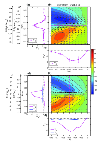
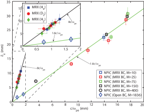
One such example measurement is shown in Fig.2(b) where the in-plane electron flow ( and ) is shown as arrows while the normalized, out-of-plane magnetic field is shown as color-coded contours in the left half of the reconnection plane. Electron outflow speed, , is also shown as functions of in Fig.2(c) (at the current sheet center) and in Fig.2(a) (across the reconnection region at the location where peaks). The dimensions of the electron layer can be characterized by the half thickness (the radial distance during which decreases by 60% from its peak value) and the half length (the axial distance during which increases from zero to its peak). We positively identify this region as the electron dissipation layer because both its dimensions, and , are independent of ion mass, as shown in Fig.3 for .
Dissipation in the electron layer is governed by the electron equation of motion,
| (1) |
where is electron mass, electron pressure tensor, and the Spitzer resistivity due to Coulomb collisions with ions (Spitzer, 1962). In the modern collisionless steady-state 2D models, the reconnection electric field, , can be only possibly balanced by either the Hall term , the inertia terms, or the electron pressure tensor term . While the Hall term is important in supporting within the ion layer (Birn et al., 2001; Ren et al., 2005; Yamada et al., 2006), it diminishes within the electron layer especially near the X-line due to the vanishing . It has been shown in particle simulations (Cai and Lee, 1997; Hesse et al., 1999; Pritchett, 2001; Kuznetsova et al., 2001) that is supported primarily by the electron pressure tensor term following earlier suggestions (Vasyliunas, 1975). This mechanism has been since widely accepted as the leading candidate to provide the required dissipation within the electron layer. It is, however, extremely difficult to confirm this pressure anisotropy, directly or indirectly, by measurements in real plasmas (Scudder et al., 2002).
One of the predictions of these 2D particle simulations is that the half thickness of the electron layer, , scales as (Pritchett, 2001). The measured in MRX, however, scales as (Fig.3). Current blockage due to the probes is estimated to lead to a increase in the measured , depending on the ratio of to the glass tube radius. Applying these corrections leads to . To better compare with the experiment, on the other hand, we have constructed a kinetic numerical model (Dorfman et al., 2008) using boundary conditions similar to the MRX based on the existing NPIC 2D code (Daughton et al., 2006). A 75cm150cm simulation box is used with conducting boundary conditions for fields and elastic reflection for particles at the walls. Two current carrying coils of radius 1.3 cm are contained within a larger concentric flux core of radius 9.4 cm. The flux cores are spaced 40 cm apart as in the experiment. The flux core surface is approximated as an insulating boundary; particles may be absorbed or reflected. Due to constraints on computation resources, the number of the Debye lengths per is limited compared to the experiment, but there is strong evidence that the reconnection rate and electron layer scalings are insensitive to this number as long as the initial plasma beta is fixed (Dorfman et al., 2008). As the current is ramped down according to a sinusoidal waveform modeled on the PF coil current of MRX and reconnection is driven, both ion and electron dissipation layers are formed. Simulation parameters are chosen such that the global reconnection rate and the current sheet thickness on the ion scale match the observations. An example run is shown in Fig.2(d-f) in the same format as in Fig.2(a-c), and most of the observed features, including geometrical shapes and out-of-plane magnetic component, are reproduced.
The quantitative agreement between experiment and simulation is, however, found for only the global ion dynamics but not the local electron dynamics. The experimentally observed independence of and on ion mass was reproduced as shown for by the open squares in Fig.3 for a fixed but artificially heavy electron mass. The values of in units of (evaluated using a line-averaged density at ), however, are much smaller in simulations than in experiments, as illustrated by an alternative ordinate in Fig.2(a) and (d). In Fig.3, a case at higher mass ratio (400) with a different electron mass is also plotted along with simulations with a realistic hydrogen mass ratio but a smaller simulation domain and open boundary conditions (Daughton et al., 2006). All of these cases, including more recent simulations using different open boundary conditions (Huang and Ma, 2008), confirm a linear relation of which is about times thinner than the experiment. In contrast, the dependence of the length of the electron layer () on is less robust; it can change significantly when the reflection coefficient parameter on the flux core surface is varied (Dorfman et al., 2008) as expected from the observed dependence of the reconnection process on boundary conditions (Kuritsyn et al., 2007).
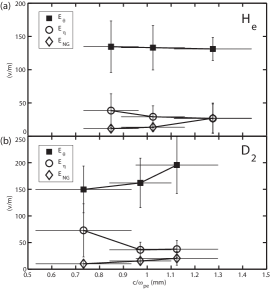
The fact that the observed electron layers are substantially thicker than the numerical predictions implies different dissipation mechanisms operating between these two cases. In fact, our collisionless simulation model does not include the residual collisions between electrons and ions or neutrals. But in MRX only a fraction of can be accounted for by the classical resistivity, (Fig.4). Collisions between electrons and neutrals, and electron collisional viscous effects are also estimated to be unimportant in these discharges with low fill pressure. The electron inertia terms, , are estimated to be on the order of 1 V/m, which is negligibly small. Near the X-line, the effects due to electron nongyrotropic pressure can be well approximated by (Hesse et al., 1999)
| (2) |
as also validated in our kinetic model. Direct evaluations of using the measured profile, as in Fig.2, gives values only a small fraction of (Fig.4). This leaves the majority of still unexplained, and therefore there must exist additional dominant dissipation mechanisms. Because our kinetic model contains all possible collisionless kinetic mechanisms operative in 2D, these dominant mechanisms must be 3D in character, including effects due to current sheet deformation or plasma turbulence through wave-particle interactions within the current sheet. The latter was indeed already suggested by the detection of electromagnetic fluctuations (Ji et al., 2004) when dissipation increases at low collisionalities (Ji et al., 1998). This subject is also under intensive theoretical and numerical investigation, such as recently by Moritaka et al. (2007), in the search for mechanisms for fast reconnection. Lastly, we comment that these 3D effects, in additional to the residual collisions, may diffuse substantially the predicted two-scale structures seen in the profiles of the reconnecting magnetic field, which remain undetected thus far in the experiment.
Acknowledgements.
The authors thank R. Kulsrud for the insightful discussions. The MRX project is supported by DOE, and the numerical comparisons reported here are mainly supported by the NASA Geosciences Program. SD was supported by the Fusion Energy Sciences Fellowship Program and the NDSEG program.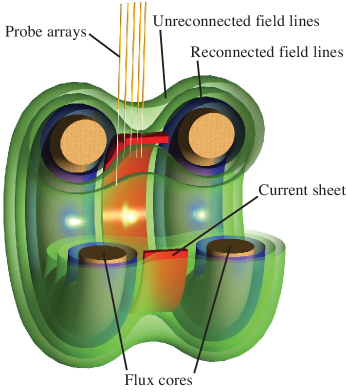
References
- Birn et al. (2001) Birn, J., et al. (2001), Geomagnetic Environmental Modeling (GEM) Magnetic Reconnection Challenge, J. Geophys. Res., 106(A3), 3715.
- Brown et al. (2006) Brown, M. R., C. D. Cothran, and J. Fung (2006), Two fluid effects on three-dimensional reconnection in the swarthmore spheromak experiment with comparisons to space data, Phys. Plasmas, 13(5), 056,503.
- Cai and Lee (1997) Cai, H. J., and L. C. Lee (1997), The generalized Ohm’s law in collisionless magnetic reconnection, Phys. Plasmas, 4, 509.
- Daughton et al. (2006) Daughton, W., J. Scudder, and H. Karimabadi (2006), Fully kinetic simulations of undriven magnetic reconnection with open boundary conditions, Phys. Plasmas, 13, 072,101.
- Deng and Matsumoto (2001) Deng, X. H., and H. Matsumoto (2001), Rapid magnetic reconnection in the earth’s magnetosphere mediated by whistler waves, Nature, 410, 557.
- Dorfman et al. (2008) Dorfman, S., H. Ji, M. Yamada, W. Daughton, V. Roytershteyn, and Y. Ren (2008), Two-Dimensional Fully Kinetic Simulations of Driven Magnetic Reconnection with Boundary Conditions Relevant to the Magnetic Reconnection Experiment, to be submitted to Phys. Plasmas.
- Hesse et al. (1999) Hesse, M., K. Schindler, J. Birn, and M. Kuznetsova (1999), The diffusion region in collisionless magnetic reconnection, Phys. Plasmas, 6, 1781.
- Huang and Ma (2008) Huang, J., and Z. W. Ma (2008), Reconnection rate in collisionless magnetic reconnection under open boundary conditions, Chin. Phys. Lett., 25, 1764.
- Ji et al. (1998) Ji, H., M. Yamada, S. Hsu, and R. Kulsrud (1998), Experimental test of the sweet-parker model of magnetic reconnection, Phys. Rev. Lett., 80, 3256.
- Ji et al. (2004) Ji, H., S. Terry, M. Yamada, R. Kulsrud, A. Kuritsyn, and Y. Ren (2004), Electromagnetic fluctuation during fast reconnection in a laboratory plasma, Phys. Rev. Lett., 92, 115,001.
- Kuritsyn et al. (2007) Kuritsyn, A., H. Ji, S. Gerhardt, Y. Ren, and M. Yamada (2007), Effects of global boundary and local collisionality on magnetic reconnection in a laboratory plasma, Geophys. Res. Lett., 34, L16,106.
- Kuznetsova et al. (2001) Kuznetsova, M. M., M. Hesse, and D. Winske (2001), Collisionless reconnection supported by nongyrotropic pressure effects in hybrid and particle simulations, J. Geophys. Res., 106, 3799.
- Mandt et al. (1994) Mandt, M. E., R. E. Denton, and J. F. Drake (1994), Transition to whistler mediated magnetic reconnection, Geophys. Res. Lett., 21, 73.
- Moritaka et al. (2007) Moritaka, T., R. Horiuchi, and H. Ohtani (2007), Anomalous resistivity due to kink modes in a thin current sheet, Phys. Plasmas, 14, 102,109.
- Mozer (2005) Mozer, F. S. (2005), Criteria for and statistics of electron diffusion regions associated with subsolar magnetic field reconnection, J. Geophys. Res., 110(A9), 12,222.
- Mozer et al. (2002) Mozer, F. S., S. Bale, and T. D. Phan (2002), Evidence of diffusion regions at a subsolar magnetopause crossing, Phys. Rev. Lett., 89, 015,002.
- Øieroset et al. (2001) Øieroset, M., T. D. Phan, M. Fujimoto, R. P. Lin, and R. P. Lepping (2001), In situ detection of collisionless reconnection in the earth’s magnetotail, Nature, 412, 414.
- Phan et al. (2007) Phan, T., J. Drake, M. Shay, F. Mozer, and J. Eastwood (2007), Evidence for an elongated ( 60 ion skin depths) electron diffusion region during fast magnetic reconnection, Phys. Rev. Lett., 99, 255,002.
- Pritchett (2001) Pritchett, P. L. (2001), Geospace Environment Modeling magnetic reconnection challenge: Simulations with a full particle electromagnetic code, J. Geophys. Res., 106, 3783.
- Ren et al. (2005) Ren, Y., M. Yamada, S. Gerhardt, H. Ji, R. Kulsrud, and A. Kuritsyn (2005), Experimental Verification of the Hall Effect during Magnetic Reconnection in a Laboratory Plasma, Phys. Rev. Letts., 95(5), 055,003.
- Ren et al. (2008) Ren, Y., M. Yamada, H. Ji, S. Gerhardt, and R. Kulsrud (2008), Identification of the Electron Diffusion Region during Magnetic Reconnection in a Laboratory Plasma, submitted to Phys. Rev. Letts..
- Scudder et al. (2002) Scudder, J. D., F. S. Mozer, N. C. Maynard, and C. T. Russell (2002), Fingerprints of collisionless reconnection at the separator, I, Ambipolar-Hall signatures, J. Geophys. Res., 107, 1294.
- Sonnerup (1979) Sonnerup, B. U. Ö. (1979), Solar System Plasma Physics, vol. 3, chap. Magneti Field Reconnection, p. 45, North-Holland, New York.
- Spitzer (1962) Spitzer, L. (1962), Physics of Fully Ionized Gases, Interscience Publishers, New York.
- Vasyliunas (1975) Vasyliunas, V. (1975), Theoretical models of field line merging, i., Rev. Geophys. Space Phys., 13, 303.
- Wygant et al. (2005) Wygant, J., et al. (2005), Cluster observations of an intense normal component of the electric field at a thin reconnecting current sheet in the tail and its role in the shock-like acceleration of the ion fluid into the separatrix region, J. Geophys. Res., 110, A09,206.
- Xiao et al. (2006) Xiao, C. J., et al. (2006), In situ evidence for the structure of the magnetic null in a 3D reconnection event in the Earth’s magnetotail, Nature Physics, 2, 478–483.
- Xiao et al. (2007) Xiao, C. J., et al. (2007), Satellite observations of separator-line geometry of three-dimensional magnetic reconnection, Nature Physics, 3, 609–613.
- Yamada et al. (1997) Yamada, M., H. Ji, S. Hsu, T. Carter, R. Kulsrud, N. Bretz, F. Jobes, Y. Ono, and F. Perkins (1997), Study of driven magnetic reconnection in a laboratory plasma, Phys. Plasmas, 4, 1936.
- Yamada et al. (2006) Yamada, M., Y. Ren, H. Ji, J. Breslau, S. Gerhardt, R. Kulsrud, and A. Kuritsyn (2006), Experimental study of two-fluid effects on magnetic reconnection in a laboratory plasma with variable collisionality, Phys. Plasmas, 13, 2119.