Cloaking a metal object from an electromagnetic pulse:
A comparison between various cloaking techniques
Abstract
Electromagnetic cloaks are devices that can be used to reduce the total scattering cross section of various objects. An ideal cloak removes all scattering from an object and thus makes this object “invisible” to the electromagnetic fields that impinge on the object. However, ideal cloaking appears to be possible only at a single frequency. To study cloaking from an electromagnetic pulse we consider propagation of a pulse inside a waveguide with a cloaked metal object inside. There are several ways to achieve cloaking and in this paper we study three such methods, namely, the coordinate-transformation cloak, the transmission-line cloak, and the metal-plate cloak. In the case of the two last cloaks, pulse propagation is studied using experimental data whereas the coordinate-transformation cloak is studied with numerical simulations. The results show that, at least in the studied cases where the cloaked object’s diameter is smaller than the wavelength, the cloaks based on transmission-line meshes and metal plates have wider bandwidth than the coordinate-transformation cloak.
I Introduction
The possibility of electromagnetic cloaking, or, in other words, the reduction of an object’s total scattering cross section, has intrigued researchers for a long time. Already in the 1960s and 1970s a few publications considered this possibility.Dolin ; Kerker But it was not until a few years ago when the topic became widely studied among the electromagnetics and physics communities after the publication of papers [3–6]. Several methods can be used to achieve electromagnetic cloaking, all of them having their own benefits and drawbacks as can be concluded from recently published review papers on this topic.Alu_review ; Alitalo_review As has been previously concluded,Alitalo_review some cloaking methods suffer from inherently strong dispersion that will unavoidably not only limit the cloaking bandwidth but also distort a pulse when it travels through the cloak. In this paper we make a comparative study of cloaking of a metal object from an electromagnetic pulse.
We study three cloaking methods: The coordinate-transformation (CT) cloak,Pendry2006 ; Schurig2006 the transmission-line (TL) cloak,Alitalo_TLcloakTAP ; Alitalo_TLcloakAPL ; Alitalo_TLcloakAPS2009 ; Alitalo_TLcloakMOTL and the metal-plate (MP) cloak.Alitalo_PPWGcloakMETA ; Tretyakov_PPWGcloakPRL Due to the moderate dispersion in the TL and MP cloaks, we expect that the cloaking bandwidth is wider and pulse distortion is mitigated in these cloaks, as compared to the CT cloak. The cloaked object is limited in shape when using the TL cloak (a transmission-line network must fit inside the cloaked object) whereas the MP cloak and the CT cloak can be used to “hide” bulk objects, such as solid metal cylinders in this case.
For the study of pulse propagation in case of the TL and MP cloaks we use transmission data measured in a waveguide with a cloak and a cloaked object inside.Alitalo_TLcloakAPL ; Tretyakov_PPWGcloakPRL In case of the CT cloak, we rely on numerical simulations of an idealized cloak having a radially varying permeabilitySchurig2006 and inserted inside a similar waveguide as the other cloaks. To have physically sound values for as a function of the frequency, we assume that has the Lorentzian type dispersion characteristics. Pulse propagation through CT cloaks that are placed in free space and are impinged on by plane waves has been studied analytically and numerically in several papers.Zhang1 ; Chen ; Zhang2 ; Argyropoulos Since in this study the cloaks are placed inside a waveguide with input and output ports, the distortion of the pulse travelling through the cloaks is very easy to illustrate and compare to the case of the empty waveguide.
II Studied cloaking devices
II.1 Transmission-line cloak
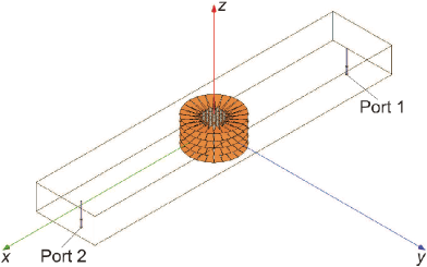
The transmission-line cloak consists of layered two-dimensional networks of parallel-strip transmission lines.Alitalo_TLcloakAPL The cloak’s outer diameter is approximately 71 mm while the cloaked object consists of 21 metal rods having the diameter 2 mm and the array period 5 mm. The largest outer dimension of the array in the -plane is 24.5 mm. It is obvious that due to the periodicity of the network an electrically large solid object cannot be cloaked with this method.
Here we use the measured data obtained with a rectangular waveguide having a passband around 3 GHz and the TL cloak enclosing the metal rod array placed inside the waveguide.Alitalo_TLcloakAPL The cloak is made by etching thin sheets composed of an alloy of bronze and beryllium. See Fig. 1a for an illustration of the measurement setup. The width and height of the waveguide are 86.36 mm and 36.8 mm, respectively and the distance between ports 1 and 2 is 389 mm.
Although the cloaked object in this case is a two-dimensional array of metal rods, it should be noted that with the same cloak also a more complicated three-dimensional object can be cloaked.Alitalo_review ; Alitalo_TLcloakAPS2009 ; Alitalo_TLcloakMOTL
II.2 Metal-plate cloak
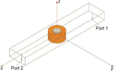
The metal-plate cloak consists of layered cylindrical metal plates that have a circular hole cut inside them (the volume which is cloaked).Alitalo_PPWGcloakMETA ; Tretyakov_PPWGcloakPRL Due to the fact that the height of these waveguide plates decreases radially as moving from the outer surface of the cloak towards the inside, the electric field which is polarized orthogonally to the metal plates travels inside these waveguides around the cloaked region. At the inner surface of the cloak the fields cannot couple into the cloaked region since the fields are concentrated in a very small volume due to the small height of the waveguides.Tretyakov_PPWGcloakPRL Note that this cloak operates for -polarized electric fields in contrast to a similar cloak geometry which is based on a different design concept.Shalaev
The inner and outer diameters of the MP cloak are 32 mm and 70 mm, respectively, whereas the diameter of the cloaked cylinder is 30 mm. The plates of the cloak are made of copper and the cloaked cylinder is made of steel. The measurement data for the MP cloak is obtained with the same waveguide as for the TL cloak.Tretyakov_PPWGcloakPRL See Fig. 1b for an illustration of the measurement setup.
II.3 Coordinate-transformation cloak
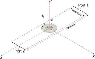
The coordinate-transformation cloak is formed of an anisotropic material layer, the material parameters of which are designed with the well-known cloak design equations that were used to design the first experimental demonstration of a cloak of this type.Schurig2006 To obtain the needed values for we design the cloak to have a radially dependent component of the permeability () having the optimal values at the design frequency of 3 GHz. See Fig. 1c for an illustration of the simulated structure. Suitable material parameters at the design frequency of 3 GHz are found to beSchurig2006
| (1) |
| (2) |
| (3) |
where is the distance from the center of the cloaked object and and are the inner and outer radius of the cloak, respectively. The losses are modelled according to the experimental setup.Schurig2006
In a realization of such a cloak device, the parameters and are constant, but the radial component of the permeability must be dispersive (otherwise such values of cannot be realized with a passive medium). Here we assume that has the Lorentzian dispersion:
| (4) |
where is the effective plasma frequency, the resonance frequency, and the damping frequency.
This is a dispersion model typical for an artificial permeability realized with split-ring-resonators. To enable good operation of the cloak and mitigate the effect of dispersion, we position the resonance frequency at a much lower frequency than the operation frequency of the cloak. Note that this may not be possible in practical designs due to too large inclusion dimensions.
To satisfy the cloaking condition at the operating frequency of GHz, we demand according to (3) that
| (5) |
from which it follows
| (6) |
| (7) |
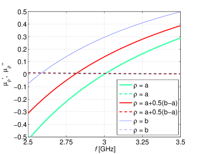
To have a fair comparison with the other cloaks, here we use the same inner and outer dimensions as for the MP cloak, i.e., mm (inner radius of the cloak) and mm (outer radius of the cloak). The diameter of the cloaked perfectly conducting cylinder is also the same as for the MP cloak, i.e., 30 mm. With GHz and GHz and using (3)–(7) we can find the values for the function and assign these values to be continuous in the simulation model of Fig. 1c. See Fig. 2 for the values of the real and imaginary parts of as a function of the frequency for three different values of inside the cloak. According to (1) .
III Numerical verification of cloaking with the studied devices
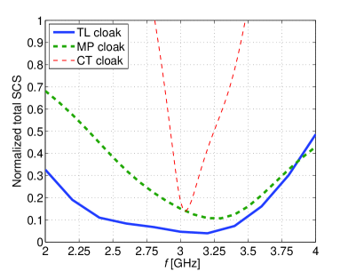
Before studying pulse propagation with the waveguide and cloak systems shown in Fig. 1, let us compare the cloaking capabilities of the studied devices using frequency domain simulations where the cloaks are placed in free space. We take the cloaks (and cloaked objects) described in Section II and model them numerically in free space. The cloaks are modelled as being infinitely periodic along the vertical () direction. By illuminating the cloaks with plane waves having the electric field parallel to the -axis we can compute the total scattering cross sections of the cloaked and uncloaked objects.Alitalo_TLcloakAPL
The results for the TL cloak and the MP cloak have been already reportedAlitalo_TLcloakAPL ; Tretyakov_PPWGcloakPRL and here we compare these with the results for the CT cloak. From Fig. 3 it is obvious that the CT cloak has a much narrower bandwidth as compared to the two other cloaks. This is an expected consequence of the dispersive nature of the permeability in the CT cloak, even though the resonance frequency of the permeability was chosen to be far away from the design frequency of 3 GHz. The minimum of the normalized total scattering cross section (SCS) occurs at 3.04 GHz for the CT cloak.
IV Measured and simulated transmission data
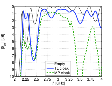
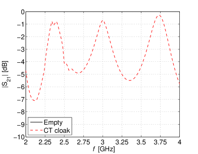
The experiments and the transmission measurements for the empty waveguide and the TL and MP cloaks shown in Fig. 1a,b have been already reported,Alitalo_TLcloakAPL ; Alitalo_TLcloakAPS2009 ; Tretyakov_PPWGcloakPRL demonstrating good transmission properties around 3 GHz. Here we compare these experimental results with the numerical results obtained for the CT cloak of the same dimension. The measured transmission magnitude and phase for the TL cloak and the MP cloak are presented in Fig. 4 and the simulated transmission magnitude and phase for the CT cloak are presented in Fig. 5. The simulations of the waveguide with the CT cloak inside are conducted with COMSOL Multiphysics.Comsol
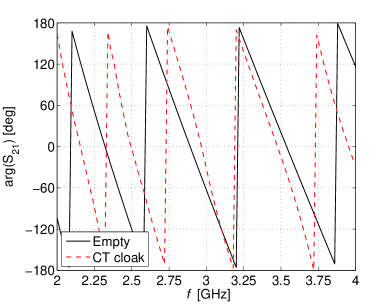
The transmission magnitude for the CT cloak has several maxima. The maximum at 3 GHz relates to the designed optimal cloaking frequency, and the other maxima result from resonances inside the cloak. From the simulated field distributions (e.g., animating the time-harmonic electric field as a function of the phase) this is obvious since at 3 GHz the electromagnetic wave that hits the cloak travels inside the cloak, whereas at the frequencies corresponding to the other maxima, the field oscillates inside the cloak. While the transmitted amplitude is close to 0 dB at the frequencies corresponding to these resonant maxima, the phase of the transmitted wave strongly deviates from the empty-waveguide case as shown in Fig. 5b.
The transmission phase difference between the cloaked and empty cases for various cloaks can be compared. For the TL cloak the phase lags as compared to the empty waveguide and this lag is growing with increasing frequency. This is expected since the wavenumber of waves travelling inside the TL cloak is not equal to the free-space wavenumber.Alitalo_review ; Alitalo_TLcloakTAP In contrast, for the MP cloak at around 3 GHz the transmission phases for cloaked and empty cases are almost identical. Below and above this frequency the phase in the MP cloak has a small lead and lag, respectively.
For the CT cloak we would expect to have identical phase shift for cloaked and empty cases at the design frequency of 3 GHz. However, the matching of the transmission phase occurs at approximately 3.1 GHz. This can be a result of the simplification of the cloak’s material parametersSchurig2006 or the influence of losses.
V Pulse distortion
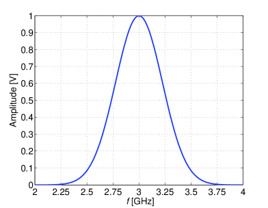
Next we study pulse propagation inside the waveguides enclosing the different cloaks. This can be investigated analytically by using the frequency-domain transmission data. First we choose the center frequency of a Gaussian pulse () that we want to transmit through the waveguide and apply a Gaussian filter to create a time-domain signal
| (8) |
where is the standard deviation and the center of the pulse corresponds to time . For GHz and the pulse looks in the frequency and time domains as shown in Fig. 6.
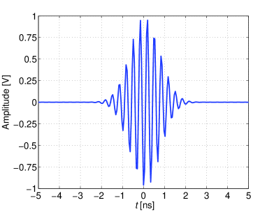
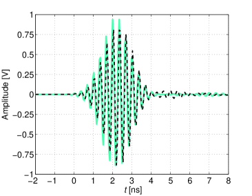
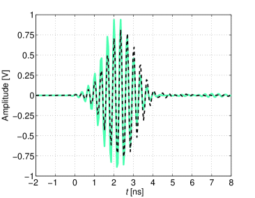
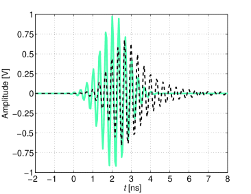
We apply the Fourier transform to the time-domain pulse and multiply each frequency component by the complex transmission coefficients presented in Section IV. Then by applying the inverse Fourier transform we find the time-domain signal at the output of the waveguide section (at port 2). Fig. 7 presents these time-domain signals for all studied cloaks together with the signals at the output of an empty waveguide when using the input pulse of Fig. 6.
From Fig. 7 we can conclude that for the TL cloak and the MP cloak the pulse shape reasonably well corresponds to the pulse at the output port of an empty waveguide. For the CT cloak, however, the pulse is clearly distorted and there is a considerable “tail” because the energy inside the cloak travels slower than in free space (the slower the closer to the inner part of the cloakAlitalo_review ; Chen ).
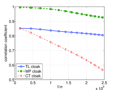
From the time-domain results in Fig. 7 it is difficult to define a numerical measure on how well or bad the cloaks work. Therefore, we calculate the correlation coefficients between the pulse which goes through the empty waveguide and the pulses which go through the cloaks. See Fig. 8 for the results as a function of the inverse of the standard deviation while GHz is kept constant. Small values of correspond to pulses which are wide in the time-domain and narrow in the frequency domain, whereas large values of correspond to pulses which are narrow in the time-domain and wide in the frequency domain.
All the cloaks work well for pulses which are narrow in the frequency domain. As the pulse bandwidth increases, the CT cloak’s operation deteriorates much faster than the operation of the other cloaks. This is expected since the CT cloak has a narrow bandwidth (see Fig. 3) and stronger dispersion as compared to the other cloaks.
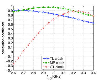
Another interesting issue is to study how the choice of the center frequency of the pulse () affects the results. Here we use a constant standard deviation of and plot the correlation coefficients as functions of , see Fig. 9. We see that the TL cloak works better for pulses for which the center frequency is significantly lower than the design frequency of 3 GHz while the MP cloak works best when the center frequency is approximately 2.9 GHz. This can be explained by Fig. 4b which shows that the optimal matching of the transmission phases of the empty waveguide and the TL cloak occurs at around 2.6 GHz while for the MP cloak the optimal frequency is approximately 2.9 GHz.
The CT cloak appears to work better for pulses with at frequencies slightly higher than the design frequency of 3 GHz. Again, this can be partly explained by the transmission phase shown in Fig. 5b according to which the optimal matching of the transmission phases for the empty waveguide and the CT cloak occurs at 3.1 GHz. Also the blueshift effectZhang1 may cause the cloak to work better for pulses above the design frequency.
VI Conclusions
Three different cloak designs have been studied and their operation compared with each other: The transmission-line cloak, the metal-plate cloak, and the coordinate-transformation cloak. The cloaking capabilities of these devices are first studied with numerical frequency-domain simulations of the cloaks in free space with plane waves illuminating the cloaks. This type of comparison enables the study of the reduction of the total scattering cross sections, but it does not give information about distortion of time-domain pulses.
To compare the cloaks’ operation for time-domain signals we use measured and simulated data for the transmission coefficients of rectangular waveguides with the cloaks (and cloaked objects) inside. With this transmission data we can analytically study how time-domain signals travel through the waveguides. It is shown that the transmission-line cloak and the metal-plate cloak work better than the coordinate-transformation cloak for pulses which are narrow in the time-domain. For pulses which are wide in time-domain (or, in other words, which are narrow in frequency domain) all the cloaks offer reasonably good performance.
Acknowledgement
This work has been partially funded by the Academy of Finland through the Center-of-Excellence program.
References
- (1) L. S. Dolin, Izv. VUZov Radiofizika 4, 964 (1961) (in Russian).
- (2) M. Kerker, J. Optical Soc. America 65, 376 (1975) (Erratum: p. 1085, Sept. 1975).
- (3) A. Alù and N. Engheta, Phys. Rev. E 72, 016623 (2005).
- (4) U. Leonhardt, Science 312, 1777 (2006).
- (5) J. B. Pendry, D. Schurig, and D. R. Smith, Science 312, 1780 (2006).
- (6) D. Schurig, J. J. Mock, B. J. Justice, S. A. Cummer, J. B. Pendry, A. F. Starr, and D. R. Smith, Science 314, 977 (2006).
- (7) A. Alù and N. Engheta, J. Opt. A 10, 093002 (2008).
- (8) P. Alitalo and S. Tretyakov, Materials Today 12, 22 (2009).
- (9) P. Alitalo, O. Luukkonen, L. Jylhä, J. Venermo, and S.A. Tretyakov, IEEE Trans. Antennas Propag. 56, 416 (2008).
- (10) P. Alitalo, F. Bongard, J.-F. Zurcher, J. Mosig, and S. Tretyakov, Appl. Phys. Lett. 94, 014103 (2009).
- (11) P. Alitalo, O. Luukkonen, F. Bongard, J.-F. Zurcher, J. Mosig, and S. Tretyakov, “Broadband cloaking of selected objects in the microwave regime with a volumetric cloak comprising layered networks of transmission lines,” Proc. IEEE International Symposium on Antennas and Propagation, Charleston, USA, June 1-5, 2009, p. 222.2.
- (12) P. Alitalo, O. Luukkonen, J. R. Mosig, and S. A. Tretyakov, Microw. Opt. Technol. Lett. 51, 1627 (2009).
- (13) P. Alitalo, O. Luukkonen, and S. A. Tretyakov, “Wide-band electromagnetic cloaking with a simple volumetric structure composed of metal plates,” Proc. Metamaterials’2009, London, UK , 30 August - 4 September 2009, pp. 405-407.
- (14) S. Tretyakov, P. Alitalo, O. Luukkonen, and C. Simovski, Phys. Rev. Lett. 103, 103905 (2009).
- (15) B. Zhang, B.-I. Wu, H. Chen, and J. A. Kong, Phys. Rev. Lett. 101, 063902 (2008).
- (16) H. Chen and C. T. Chan, J. Appl. Phys. 104, 033113 (2008).
- (17) B. Zhang, B.-I. Wu, and H. Chen, Opt. Express 17, 6721 (2009).
- (18) C. Argyropoulos, Y. Zhao, and Y. Hao, IEEE Trans. Antennas Propagat. 57, 1432 (2009).
- (19) I. I. Smolyaninov, V. N. Smolyaninova, A. V. Kildishev, and V. M. Shalaev, Phys. Rev. Lett. 102, 213901 (2009).
- (20) Ansoft’s homepage: http://www.ansoft.com/
- (21) COMSOL’s homepage: http://www.comsol.com/
Figures