Cloaking a Sensor via Transformation Optics
Abstract
Ideal transformation optics cloaking at positive frequency, besides rendering the cloaked region invisible to detection by scattering of incident waves, also shields the region from those same waves. In contrast, we demonstrate that approximate cloaking permits a strong coupling between the cloaked and uncloaked regions; careful choice of parameters allows this coupling to be amplified, leading to effective cloaks with degraded shielding. The sensor modes we describe are close to but distinct from interior resonances, which destroy cloaking. As one application, we describe how to use transformation optics to hide sensors in the cloaked region and yet enable the sensors to efficiently measure waves incident on the exterior of the cloak, an effect similar to the plasmon based approach of Alù and Engheta AE .
pacs:
42.70.-a,33.20.Fb,42.50.Gy,42.79.-eIntroduction - Transformation optics has led to designs for devices having radical effects on wave propagation, one of the most compelling of which is cloaking PSS1 ; Le . The complex material parameters of a transformation optics cloak steer the rays around the region to be hidden, and to a large extent the behavior of the waves mimics that of the rays. However, the literature on such cloaks leaves the impression that transformation optics cloaking produces a decoupling of the waves within and external to the cloaked region, cf. AE ; CummerPRE ; RYNQ ; McG ; Cast ; Gar . In this paper, we show that on the contrary, rather than being isolated, the cloaked region in fact has a coupling with the environment surrounding the cloak, and this may be amplified by means of carefully chosen parameters within the cloaked region. There is thus a fundamental difference between cloaking for rays and cloaking for waves. We emphasize that the cloaking effectiveness can be made arbitrarily close to the ideal cloak, while keeping the sensing effectiveness fixed. Although we focus on scalar equations in the quasistatic and finite frequency regimes, modeling electrostatic GLU1 and acoustic cloaks ChenChan , the same phenomenon holds with regard to transformation optics cloaking for transversely polarized EM waves, e.g., in the cylindrical geometry GKLU1 . Similar considerations allow sensors to be cloaked from observation by static heat flow or certain cases of matter waves Zhang ; GKLU3 .
For electromagnetism in the quasistatic regime, it was already shown in GLU1 that the mean voltage on the exterior surface of an ideal cloak can be measured anywhere inside the cloaked region. At nonzero frequencies, ideal cloaking PSS1 is accompanied by perfect shielding, meaning that an observer or device within the cloaked region cannot detect any information about the incident wave GKLU1 . Furthermore, approximate cloaking is also accompanied by approximate shielding RYNQ ; GKLU3 except near certain exceptional frequencies (Neumann eigenvalues of the interior), for which the resulting resonance simultaneously destroys both the cloaking and shielding effects GKLU3 .
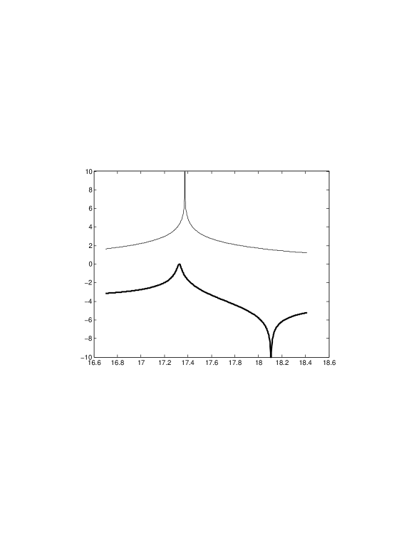
Here, we consider waves modeled by the Helmholtz equation in three dimensions. In electrostatics, and denotes the conductivity; in acoustics, , and and correspond to the anisotropic mass density and bulk modulus, resp. For waves governed by Helmholtz, we describe a sensor effect, in which the combination of an approximate cloak and an inner layer implementing a carefully chosen Robin boundary condition on its inner surface results in effective cloaking but degraded shielding, so that the lowest harmonics of incident waves penetrate deeply into the cloaked region; see Fig. 1. The sensor effect occurs close to but not at interior resonances, and constitutes a new phenomenon. In terms of the design parameters, there are three regimes: generic (standard) cloaking, resonance, and the sensor effect; see Fig. 2 (left). The double peak in Fig. 2 (right) at corresponds to the deterioration of both cloaking and the sensor effect at a resonance; the single dip to its right at corresponds to the sensor mode at which cloaking is actually improved.
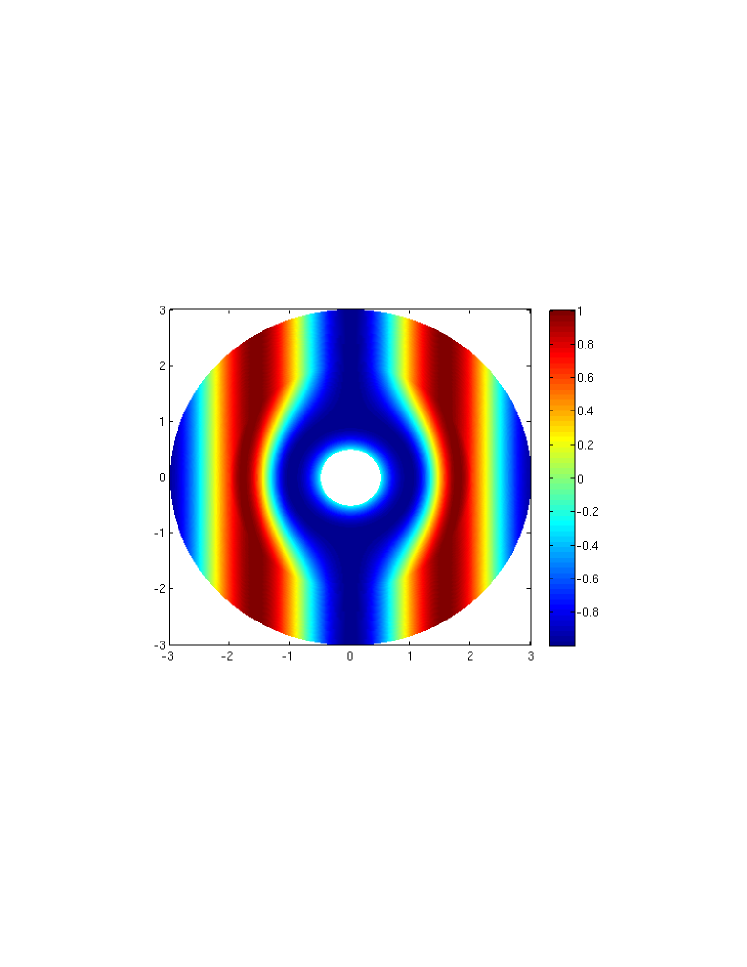
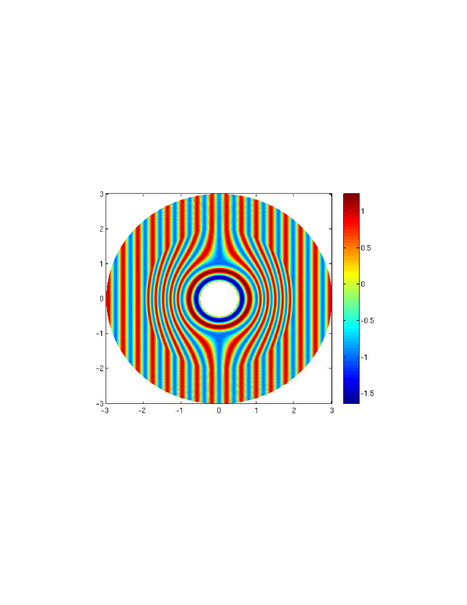
In AE , Alù and Engheta showed how a plasmonic coating can be used to render an electromagnetic sensor almost invisible to detection by incident waves, while allowing the sensor to remain effective as a device for measuring those very waves. We exploit the enhanced coupling effect described above to show that transformation optics cloaking also allows for cloaked sensors, with a sensor embedded inside the cloaked region efficiently measuring the incident waves without markedly altering them. In contrast to the plasmon based technique of AE , this method works well for objects quite large compared with the wavelength, cf. Fig. 1(bottom). Furthermore, the quality of the approximate cloaking effect is actually improved at a sensor mode, with the higher order harmonics vanishing to third order in the small parameter we use for asymptotics. Plasmonic cloaking is also related to the polarizability theory cf. Sihvola .
We remark that our construction, using only right-handed media, is distinct from the anti-cloak AntiCloak , which destroys both cloaking and shielding and requires LHM. The effect described here is also distinct from the sensitivity of the ideal cloak to small perturbations, which degrade cloaking and shielding simultaneously RYNQ , as well as interior resonance effects for approximate cloaks that have been reported previously GKLU3 ; KOVW . One of the surfaces in our construction is covered with material inducing a real Robin condition, corresponding to an imaginary impedance, ; cloaking by a thin mantle of such material has been proposed by Aù Alu , but this appears to be a different effect than ours. Finally, we note that Sklan Sklan also describes penetration of waves into a cloaked region. However, the nature of that phenomenon is quite different from the one described here. Indeed, Sklan (a) shows penetration of momentum into a region infinitesimally close to the cloaking surface (the inner surface of the cloak), corresponding to the gradient of the jump in the pressure field across the surface, while the waves we study occupy the entire cloaked region; (b) deals with ideal cloaking, while the phenomenon we consider occurs only for approximate cloaking and disappears in the ideal limit; and (c) describes effects which occur at any frequency, while the effects described here are parameter sensitive, being due to a delicate energy balance near, but not at, interior resonant frequencies.
Quasistatic regime - For simplicity, we work throughout with three dimensional, spherical transformation optics cloaking. In the quasistatic regime, the analysis can be based on ideal cloaking for electrostatics GLU1 . The solutions for the ideal cloak considered in GLU1 are the limits of solutions for more realizable approximate cloaks. Let and , resp., denote the 3D ball of radius centered at the origin , and its boundary, the 2D sphere. For any , transformation optics (see the transformation in (3) below for ) specifies an inhomogeneous, anisotropic cloaking conductivity on the 3D spherical shell , such that for any passive object, i.e., one without sources or sinks in , the boundary measurements of electrostatic potentials at the outer boundary coincide with those made when is filled with a homogeneous, isotropic conductivity , yielding a perfect cloaking effect. Given a boundary voltage distribution on , the potential corresponding to takes a value at the origin, , where is normalized surface measure. The potential corresponding to the same voltage , but with the object in surrounded by the cloak , is constantly equal to on GLU1 . Thus, even for the ideal quasistatic cloak, the cloaked region is not electrically isolated, or shielded, from its environment; rather, any passive sensor in measures the mean voltage at , while not affecting the potential outside of .
Finite frequency - At finite frequency , the same singular transformation from virtual to physical space, applied to homogeneous, isotropic mass density and bulk modulus , yields an ideal cloak corresponding to as in PSS1 ; ChenChan . Analysis of finite energy waves on the entire region was given in GKLU1 , both for the Helmholtz equation and Maxwell’s equations; we consider only the former. At frequency , the wave within can be an arbitrary eigenfunction with Neumann, i.e., perfectly reflecting, boundary condition at . Thus, must vanish if is not a Neumann eigenfrequency of , yielding an idealized decoupling of the cloaked region from . This decoupling is stable, resulting in the cloaking remaining highly effective, even when the ideal cloak is replaced by more physically realistic approximate cloaks, see GKLU3 . On the other hand, if is an eigenfrequency, the approximate cloak supports almost trapped states, i.e., resonances, which have very small amplitude near while being almost equal to eigenfunctions of on GKLU3 .
We show below that one can create a device containing an almost cloaked yet highly sensitive sensor, consisting of three parts: For to be chosen, we form an approximate cloak in the spherical shell , which tends toward the ideal cloak as . It is convenient to express parameters and asymptotics in terms of the small quantity , which as . Surround this approximate cloak by a spherical shell having , on whose outer surface the external waves will be incident. For a value of , also to be chosen, we then embed a sensing element in the ball , clad with a surface whose (complex) impedance induces a real Robin boundary condition, on , with a real parameter to be chosen. Finally, between the innermost two components, we insert a layer , which, for simplicity, we take to have . Another variant of the above construction occurs when, instead of an obstacle with Robin boundary condition, place inside the cloak (i) a smaller obstacle with a Dirichlet (sound-soft) boundary condition; and (ii) a spacer layer of homogeneous and isotropic material with and being a constant chosen so that the radially symmetric solution of the obtained equation satisfies . With this Dirichlet obstacle and spacer layer included, the analysis below is valid mutatis mutandis. In acoustics, such a Dirichlet obstacle corresponds to a sound-soft surface, i.e., a freely moving boundary. If one places inside the ball a device which measures the Neumann boundary value of the solution on the sound-soft boundary , i.e., the normal component of the moment of the surface having the velocity , then this may be measured using another modality, say optically, resulting in an approximately cloaked sensor which can measure without significant energy loss.
For the device considered above, we first show that and may be chosen to allow the total device to support a resonant wave , of very small amplitude in and almost equal to a central (i.e., rotationally symmetric) Robin-Neumann eigenfunction of unit energy in the spacer . Moreover, we show that by varying to a nearby value with as , the resonance effect is changed into a sensor effect: the resulting wave is proportional, at , to the value that the wave would take at the origin in the absence of the device.
The sensor is nevertheless effectively cloaked from an outside observer, since the Dirichlet-to-Neumann map on , i.e., the operator mapping the Dirichlet boundary value on to the Neumann boundary value on , remains equal to the free space Dirichlet-to-Neumann map, up to a perturbation order .
Analysis of approximate cloaks - To see this in more detail, we recall some facts concerning nonsingular approximations to ideal cloaks. To start, let , and set , so that as . Introduce the coordinate transformation ,
| (3) |
For (), this is the singular transformation of GLU1 ; PSS1 , leading to the ideal transformation optics cloak, while for (), is nonsingular and leads to a class of approximate cloaks RYNQ ; GKLU3 ; KOVW . Thus, if denotes the homogeneous, isotropic tensor, then for the transformed tensor is nonsingular on , i.e., its eigenvalues are bounded from above and below (with, however, the lower bounds of two of them going to as ). We then define the approximate cloak tensor on as
| (7) |
Here, is the standard cloaking tensor. Define also a scalar bulk modulus,
| (11) |
Now place inside the cloak a scatterer of radius , with a surface whose impedance induces a real Robin boundary condition on the sphere . Thus, we consider in the domain the solutions of the problem,
| (12) | |||||
for an impedance to be specified later. As and are now nonsingular everywhere, across the internal interface we have the standard transmission conditions,
| (13) | |||
where is the radial unit vector and indicates the trace on as . We note that the approximate cloak with anisotropic density tensor can also be approximated, with arbitrarily precision, by a cloak with isotropic density GKLU3 .
In the physical space we have
| (16) |
with in the virtual space, which consists of the disjoint union , satisfying
| (17) | |||
With respect to spherical coordinates , the transmission conditions (13) become and . Since are spherically symmetric, we can separate variables in (12), representing as
| (18) |
where are the standard spherical harmonics. Then equations (12) give rise to a family of boundary value problems for the . For our purposes, the most important one is for the lowest harmonic term, , i.e., the radial component of , which is independent of . This is studied in the next section.
Lowest harmonic and the sensor effect - Consider the problem (12) with , so that , and express asymptotics of the waves in terms of . Analysis of the solutions reveals three distinct regimes, depending on the Robin coefficient . This can be seen informally, building up the wave inwards, from the exterior of the cloak, through the cloak, and into the cloaked sensor region, as follows. On the spherical shell , a radial solution of (12) solves the ODE
| (19) |
An incident wave has Cauchy data (i.e., the value of the wave and its normal derivative) . Using this as initial conditions for (19) at the right endpoint of , one then finds the Cauchy data at the left endpoint, . Applying the transmission conditions (13), one then finds . Continuing inward through the approximate cloak, we solve the initial value problem with this Cauchy data for
cf. GLU1 ; GKLU1 , evaluate the Cauchy data at , and then use (13) again to find . In the spacer layer , satisfies (19), with initial conditions at determined by the above procedure, so that finally we may evaluate . Starting with , gives a value of the impedance which induces a resonant, or trapped, wave, . On the other hand, starting with gives corresponding to the sensor effect and giving rise to the sensor solution, . A calculation shows that is close to : for some , one has , as . Thus, the sensor effect is quite sensitive to perturbations.
More careful analysis confirms the following three regimes, depending on how close is to :
(i) Cloaking for generic impedance. If is bounded away from i.e., , or even when for some , then the cloak acts as an effective approximate cloak, and the field goes to zero in the cloaked region as , so that there is no sensor effect.
(ii) Resonance effect. For the specific value , the interior resonance leads to both the destruction of cloaking and the absence of shielding, since then is an eigenfrequency of the equation (12) with boundary condition on and on .
(iii) Cloaking with sensor effect. For the value , the cloak acts as an effective approximate cloak, but inside the cloaked region the solution is proportional to the value which the field would have had at the origin in free space, with proportionality of order as , that is, for , where is a not identically vanishing function and is the value at of the solution to the free-space Thus, in the sensor mode the cloak functions as an “invisible magnifying glass”, where the value which the field would have had in the empty space at a single point can be measured anywhere inside the cloak. This allows one to enclose a measurement device which does not affect the incident fields being measured.
If is the resonance solution and is a general cloaking solutions, i.e., they are the radial solutions of (17) corresponding to and a generic Robin coefficient bounded away from , the radial sensor solution can be obtained as a linear combination where are chosen so that the scattering vanishes, and is obtained by computing the suitable Robin coefficient for this particular solution. Roughly speaking, when , the frequency is so close to the eigenfrequency of the inside of the cloak that the energy flux from the inside to outside and from the outside to inside through the surface are balanced. The solution inside the cloak does not blow up and the energy flux from the inside cancels the scattering caused by the fact that the cloak is only an approximate cloak, not a perfect cloak. Animations of the three regimes, are provided in vids with , . For the sensor effect, , and for the generic cloaking, , we solve the scattering problem in with an incident plane wave and use in (18). For the resonance effect, and .
We now analyze these effects quantitatively. As a wave incident to the cloak can be written in terms of Bessel functions and the scattered wave in terms of Hankel functions , the scattering effect for the zeroth order harmonic can be numerically measured by the ratio , where the zeroth order harmonic of the total field is . Cloaking then corresponds to , while the breakdown of cloaking takes place when . Similarly, quantify the shielding effect by defining , so that corresponds to effective shielding of the cloaked region from the incident waves; corresponds to the resonance regime; and the sensor effect corresponds to the case when stays between positive constants as so that the field inside the cloaked region gives adequate information about the external field.
A parameter with , or even with , for some , corresponds to the standard effects of both cloaking and shielding. The values of near , namely , correspond to the resonance effect, with . However, a new phenomenon appears in the region near , namely . In this region while , i.e., cloaking is effective but shielding is degraded. Moreover, for the higher order spherical harmonic components corresponding to we can introduce figures of merit and similar to , resp. Then, for ,
showing that, for the higher harmonics there is both a strong shielding effect, i.e., lack of sensor effect, and an almost ideal cloaking. Comparing the formulae above with the situation for , we see that the effect of the higher harmonics is comparatively negligible: one still has almost ideal cloaking and sensor effects. Hence, if a measurement device inside the obstacle implements this Robin boundary condition, then the device can measure the mean value of the wave on the boundary of the obstacle. Thus, an observer inside the cloaked region is able to measure the outside fields, while these measurements do not disturb the field outside the cloaking device. Observe that the cloaking and the sensing at is effectively independent of , as . Recall that the cloak in the sensor mode operates with time-harmonic waves with given frequency . Thus, if a device producing a time-harmonic source is activated outside the cloak, there is a delay before the wave reaches its time-harmonic steady state and the zeroth order component fully penetrate the cloak. Since the approximate cloak corresponds to a small object in the virtual space KOVW , which has a small cross-section, the smaller is the less energy is transferred into the cloaked region, and the longer it takes before the wave reaches its sensor mode state there. This explains why the sensor effect disappears in the case of ideal cloaking; indeed, in this case the time delay becomes infinite. Finally, we again note that the fact that , shows that the sensor/resonance effect is highly sensitive to the value of . By readjusting , an interior observer can tune this sensor to any desired frequency .
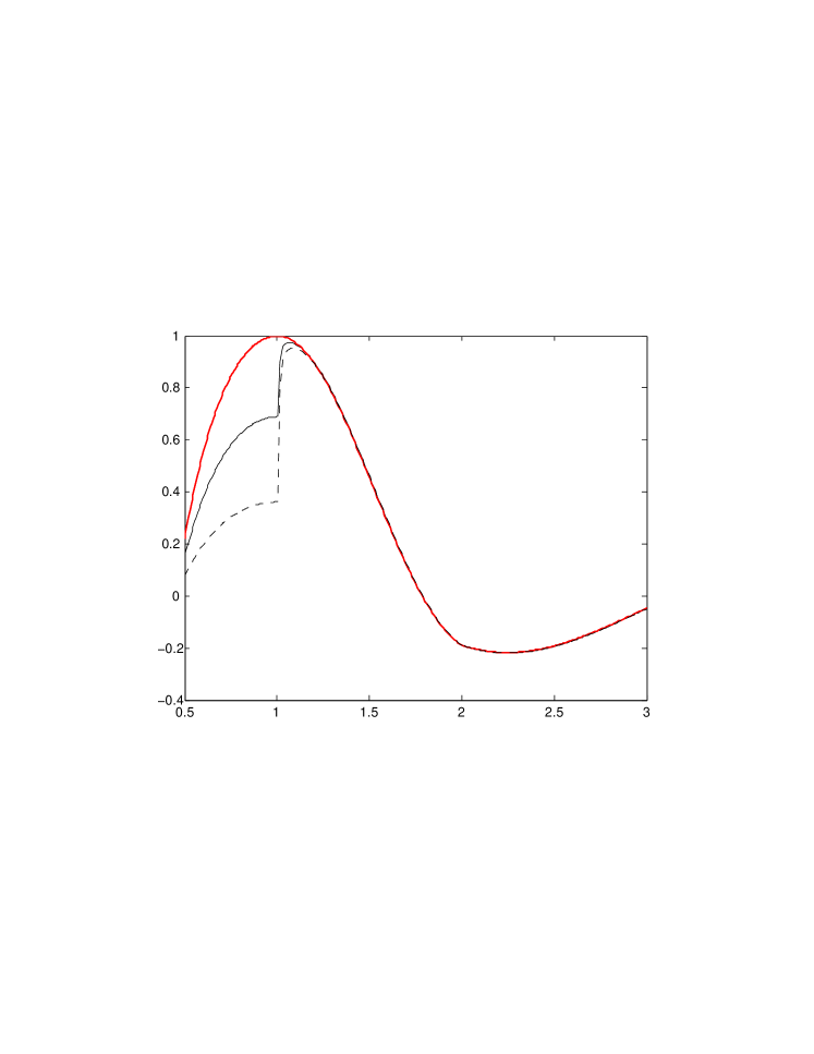
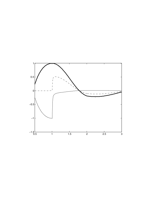
Analysis of energy loss - Finally, since measuring the wave on the Robin-boundary (or on the Dirichlet-boundary if we use the spacer layer and a sound soft obstacle) will result in some energy loss, we analyze how this loss affects the sensing and shielding. To this end, we compute the solutions in the case when the real Robin coefficient has been replaced by a complex one, . In the numerical simulations is tuned so that with the frequency and we have sensor effect, that is, . We considered two values of , namely when and , that is, the imaginary part is either 3% or 6% of the real part. Values of (sensing) and (scattering ) in the table below correspond to the solutions in Fig. 3. As seen in Fig. 3 and the table, increasing energy loss starts to degrade the sensing effect, but the scattering does not grow very much. Thus, even for the parameter value for which the cloaking effect is relatively strong, the energy loss does not destroy the cloaking property. However, due to energy loss the magnitude of the field becomes smaller inside the cloak, and thus on the interior boundary. Thus, in the presence of energy loss, the field needs to be measured with a more sensitive device.
TABLE 1. Sensing and cloaking figures of merit
in the presence of energy loss.
Discussion - We have described a new effect for transformation optics based cloaking. In the quasistatic regime, it was previously known that the mean voltage on the exterior surface of the cloak can be measured anywhere inside the cloaked region GLU1 . On the other hand, at nonzero frequencies, ideal cloaking Le ; PSS1 is accompanied by shielding GKLU1 : there is a decoupling of the fields inside and outside of the cloaked region, so that external observations do not provide any indication of the presence of a cloaked object, nor is any information about the fields outside detectable inside the cloaked region. Approximate shielding goes hand in hand with approximate cloaking, with the shielding improving as the cloaking does, except at resonant frequencies, at which both are destroyed GKLU3 . We have described a sensor effect that breaks this connection between cloaking and shielding, allowing the former without the latter, showing that transformation optics permits sensors to be cloaked. This effect occurs close to, but not at resonance, and is a distinct phenomenon. The sensor effect exists for any type of wave governed by (or reducible to) the Helmholtz equation, including scalar electromagnetism, acoustics and matter waves. It would be interesting to understand to what extent it holds for other systems, such as Maxwell’s equations. Our construction likely generalizes to Maxwell for 3D cloaks in the cylindrical geometry. However, as Maxwell’s equations do not have spherically symmetric solutions, the extension of the sensor effect to the spherical geometry remains unclear.
Acknowledgements: AG and GU are supported by US NSF, YK by UK EPSRC, ML by CoE-213476, and GU by a Walker Family Endowed Professorship at UW.
References
- (1) A. Alù and N. Engheta, Phys. Rev. Lett. 102, 233901 (2009).
- (2) U. Leonhardt, Science 312, 1777 (2006), U. Leonhardt and T. Tyc, Science 323, 5910 (2008).
- (3) J.B. Pendry, D. Schurig and D.R. Smith, Science 312, 1780 (2006).
- (4) S. Cummer, B. Popa, D. Schurig and D. Smith, Phys. Rev. E74, 036621 (2006).
- (5) Z. Ruan, M. Yan, C. Neff and M. Qiu, Phys. Rev. Lett. 99, 113903 (2007).
- (6) J. McGuirk and P. Collins, Opt. Exp. 16, 17560 (2008).
- (7) G. Castaldi, et al., Opt. Exp. 17, 3101 (2009).
- (8) F. García de Abajo, Physics 2, 47 (2009).
- (9) A. Greenleaf, M. Lassas and G. Uhlmann, Physiol. Meas. 24, 413 (2003); Math. Res. Lett. 10, 685 (2003).
- (10) H. Chen and C.T. Chan, Appl. Phys. Lett. 91, 183518 (2007); S. Cummer, et al., Phys. Rev. Lett. 100, 024301 (2008); A. Greenleaf, et al, arXiv:0801.3279v1.
- (11) A. Greenleaf, Y. Kurylev, M. Lassas and G. Uhlmann, Comm. Math. Phys. 275, 749 (2007).
- (12) S. Zhang, D. Genov, C. Sun and X. Zhang, Phys. Rev. Lett. 100, 123002 (2008).
- (13) A. Greenleaf, Y. Kurylev, M. Lassas and G. Uhlmann, Phys. Rev. Lett. 101, 220404 (2008); New J. Phys. 10, 115024 (2008); arXiv:0812.1706 (2008), J. Spectral Theory, to appear.
- (14) I. Lindell, A. Sihvola, S. Tretyakov, A. Viitanen, Electromagnetics Waves in Chiral and Bi-isotropic Media, Artech House, 1994.
- (15) See EPAPS Document No. [TBA] for three animated simulations of cloaking device in generic, sensor and resonance regimes.
- (16) H. Chen, X. Luo, H. Ma and C.T. Chan, Opt. Exp. 16, 14603 (2008).
- (17) R. Kohn, D. Onofrei, M. Vogelius and M. Weinstein, Comm. Pure Appl.Math. 63, 973 (2010).
- (18) A. Aù , Phys. Rev. B80, 245115 (2009).
- (19) S. Sklan, Phys. Rev. E81, 016606 (2010).