Anomalous Quantum Interference Induced by Landau-Zener Transitions in a Strongly Driven rf-SQUID Qubit
Abstract
We irradiated an rf-SQUID qubit with large-amplitude and high frequency electromagnetic field. Population transitions between macroscopic distinctive quantum states due to Landau-Zener transitions at energy-level avoided crossings were observed. The qubit population on the excited states as a function of flux detuning and microwave power exhibits interference patterns. Some novel features are found in the interference and a model based on rate equations can well address the features.
pacs:
74.50.+r, 85.25.CpCoherent quantum dynamics of superconducting Josephson qubits driven by weak external field have been extensively investigated in experiments. Nakamura ; Vion ; Yu ; Chio ; Satio ; Lisenfeld These experiments used Rabi oscillation to probe the macroscopic quantum coherence of such systems in the time domain, where the driving frequency equals to the energy-level separation. On the other hand, quantum coherence can also be investigated with a large-amplitude field, which can drive the qubit throughout its energy-level spectrum. In this case, Landau-Zener (LZ) transition process occurs around each level-crossing position with a finite probability while the quantum evolution is adiabatic away from the level-crossing positions.Shytov ; Shev Repetition of LZ transitions gives rise to Stuckelberg or Ramsey-type oscillations Stuck ; Ramsey in analogy to Mach-Zehnder (MZ) interferometer. The MZ-type interference is a unique quantum coherence signature complementary to Rabi oscillation.
Recently, coherent dynamics of superconducting qubits in the strongly driven regime dominated by LZ transitions were extensively studied, especially in two level systems, providing an alternative method to manipulate and characterize the qubit.Sill ; Izma ; Shev2 ; Oliver ; Berns A recent work makes a step forward Berns2 : the superconducting flux qubit as a multi-level system was driven through several avoided crossings between energy levels. The qubit population under large-amplitude fields exhibited a series of diamond-like interference patterns in the space parameterized by static flux detuning and microwave amplitude. Spectroscopic information can be obtained from the field amplitude dependence of the qubit population. Rudner That experiment was done with a superconducting persistent-current qubit, which has relatively a small loop size and a long coherence time. The applied microwave frequency was much smaller than the energy-level spacing between discrete energy levels and therefore the resonant peaks/dips tend to merge into a continuous band.
Comparing with a superconducting persistent-current qubit, an rf-SQUID qubit has a much larger geometric loop size (about 100 times larger in loop area) which usually leads to a very short coherence time (1 ns). In order to observe LZ interference in such a large system, the time interval between subsequent LZ tunneling events should be less than the relevant coherence time, indicating a high-frequency field is required. In a previous work, Guozhu we observed the quantum interference fringes in an rf-SQUID qubit due to LZ transitions at one energy-level avoided crossing. In this paper, we report the observation of simultaneous presence of two-set of interference fringes associating with LZ transitions at two nearby avoided crossings. In addition, the qubit population can be modulated by the field amplitude at certain static flux bias points. We developed a model based on rate equations and addressed these features very well.
Our sample was fabricated with Nb/AlOx/Nb trilayer on an oxidized Si wafer by using the standard photolithography method. As shown in Fig. 1(a) and 1(b), the rf-SQUID qubit is essentially a superconducting loop with a second order gradiometric configuration interrupted by a small dc-SQUID. When an external magnetic flux colse to , where is the flux quantum, is applied to the qubit loop, the system potential takes a double well shape. The flux states in different wells, serving as the qubit states, correspond to macroscopic circulating currents flowing in opposite directions. Two on-chip current bias lines are used to control the magnetic flux applied to the qubit loop () and the small dc-SQUID loop () respectively. determines the asymmetry of the potential and modulates the potential barrier height. By adjusting and , the shape of the system potential can be fully controlled . An additional on-chip current bias line is used to supply microwave (MW) pulses. The qubit flux states can be read out by a hysteretic dc-SQUID inductively coupled to the qubit loop. We can easily bias the readout dc-SQUID at its maximum sensitivity region by applying an external magnetic flux ().

The sample was placed on a chip carrier enclosed in a superconducting aluminum sample cell and the experiments were performed in a dilution refrigerator at a base temperature about 20 mK. The device was magnetically shielded and all electrical lines were carefully filtered and equipped with proper cold attenuators to minimize circuit noise (see Ref.Guozhu2 for detailed description).
In our experiment, we biased at a certain value such that the critical current of the small dc-SQUID is close to its maximum. Therefore the barrier between two potential well maintained at a relatively high value. There are several flux states below the top of the barrier in each potential well. The inter-well flux state transition rate between the ground states of two potential wells is very small at flux biases close to . Since the intra-well relaxation time is very short, the state of the qubit freezes quickly after turning off microwave irradiation. The time sequence of measurement is shown in Fig. 1(c). For each measurement cycle, a 10 s microwave pulse is applied to the qubit loop to induce sinusoidal excursions through the energy levels about a static flux detuning = - . After a delay time about 1 s, the readout is performed by driving the dc-SQUID with a current pulse comprising a 15 ns sampling current followed by a 15 s holding current just above the retrapping current of the dc-SQUID. By properly adjusting the magnitude of the readout current pulse, the dc-SQUID either switches to finite-voltage state or stays at zero voltage state corresponding to the qubit states being in left well or in right well . The measurement repetition frequency is 5 KHz. By repeating the trials for 4104 times, we obtained the average switching probability, representing the population in state. By changing the flux detuning and microwave power step by step, we then measured the dependence of qubit population in state on flux detuning and microwave power.
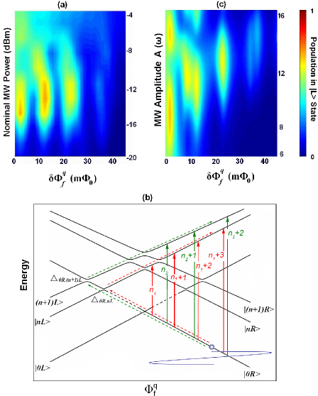
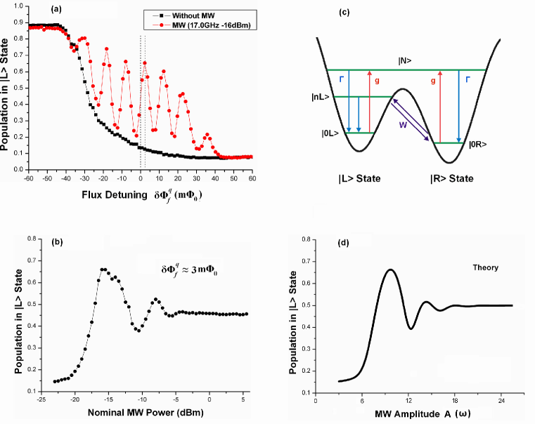
Fig. 2(a) shows the resonant peaks and dips when applying a microwave with frequency 17.0 GHz and nominal power -16 dBm. The peaks (dips) reflect the mcrowave induced excitation from flux state to ( to ). The width of the resonant peaks/dips is generally on the order of several m and the decoherence time of our system is estimated to be less than 1 ns. The strong population inversion is evident, suggesting that higher energy levels other than the first two lowest states are involved. Guozhu Without microwave the qubit step center is shifted away from the symmetry position of the energy spectrum (marked by the left dotted line in Fig. 2(a)) due to the presence of the circulating current in the readout dc-SQUID. Chio Then we fixed the flux bias and swept microwave power. Fig. 2(b) shows the qubit population in state as a function of the nominal microwave power at a static flux detuning = 3 m (marked by the right dotted line in Fig. 2(a)). The population exhibits a damped oscillation around 0.5. For two level systems, a good Bessel function dependence of the population on microwave amplitude was observed in a superconducting persistent current qubit and the modulation period is proportional to the ratio of microwave amplitude and the microwave frequency. Oliver Therefore, in our experiments a large microwave power is required to observe the periodic behavior since the microwave frequency is very large. However, for a very high microwave power, the LZ transitions are not the dominant processes anymore. To make a more quantitative understanding, we hereby propose a simple model, which is illustrated in Fig. 2(c). The qubit is initialized in , the ground state of right well. When the microwave amplitude is not very large (i.e., the double well potential always exits), the LZ transitions (with rate ) between and (the th excited state of left well), and the fast intra-well relaxation (with rate ) from to dominate the dynamics of the qubit population. These processes cause qubit population inversion and lead to the non-monotonic dependence of qubit population on microwave power. When the microwave amplitude goes up, it is much easier for the the qubits to be directly excited from the ground state to a higher energy level (with rate ), which is above the top of the barrier and has a wavefunction spanning both potential wells. The qubit population in tend to fast relax back to the ground states ( and ) of both wells with an approximately equal relaxation rate and therefore this process equalizes the qubit population in the two wells. Taking all transition processes into consideration, one can obtain the rate equations to describe the qubit level occupations , corresponding to , , and respectively) as:
| (1) |
Under the assumption of classical noise and using perturbation theory, the LZ transition rate between and takes the formRudner :
| (2) |
where is the avoided crossing between and , is the dc energy detuning from the avoided crossing and is the system dephasing rate. are Bessel functions of the first kind with the argument , where and are field amplitude and frequency respectively. For a -photon transition process, when on resonance, the LZ transition rate approximately reduces to:
| (3) |
The transition rate from the ground state to is sensitive to the barrier height during the microwave driving process. We simply assumed the transition rate have an exponential dependence on field amplitude , i.e., = , where , are two fitting parameters. () is the slow inter-well relaxation rate between and . In the stationary case, , Eq.(1) can be solved numerically with appropriate model parameters. Fig. 2(d) shows the calculated qubit population of state as a function of the microwave amplitude. The theoretical curve clearly exhibits the main features of the experimental results, indicating our model captured the underlying physics of the system.
Fig. 3(a) shows the contour plot of the qubit population in state versus the positive static flux detuning and the nominal microwave power with a fixed microwave frequency at 17.0 GHz. According to the previous worksOliver , we expect that the resonant peaks are equally spaced on the flux axis and the distance between the adjacent peaks corresponds to the microwave frequency. With the amplitude increasing, the resonant peaks emerge one by one, starting from the flux close to The flux position for each peak almost does not change while the population follows the Bessel functions of the first kind. However, here we observed two sets of the resonant peaks. The first set includes four resonant peaks, locating at around flux detuning 3 m, 12 m, 23 m, and 37 m respectively. The second set lies in the higher microwave power region and includes three resonant peaks, locating at around flux detuning 10 m, 22 m, and 38 m respectively. We can group them into two sets because as microwave frequency varies, their flux bias positions move with two different energy-spectrum slopes, indicating two different transition paths are present. The two interference sets have overlap along microwave power axis. In addition, the distance of the resonant peak increases with the flux detuning. Therefore, the interference pattern looks a little complicated and is different from the regular patterns induced by Landau-Zener transitionSill ; Izma ; Shev2 ; Oliver ; Berns ; Guozhu . In order to explain the interference we have to deal with the multi-level system. Since the barrier of the rf-SQUID is very high, the Landau-Zener transition rate is very low for the lower energy states. We thereby consider the avoided crossings close to the top of the barrier, which is qualitatively illustrated in Fig. 3(b). The qubit is initially in state at a certain static flux bias . The first set is associated with LZ transitions at level crossing (also , not shown in Fig. 3(a) for simplicity) and the red path represents the main transition processes for generating the first set. The second set is associated with LZ transitions at level crossing (also ) and the green path represents the main transition processes for generating the second set. The fours peaks in the first set correspond to -photon and up to (+3)-photon transitions and the three peaks in the second set correspond to -photon and up to (+2)-photon transitions. The slope of the green path is smaller than that of the red path. Therefore the flux spacing of the resonant peaks of the second set is larger than that of the first set. On the other hand, the slopes of the energy levels close to the top of the barrier are flattened, leading to the increase of the distance of the resonant peaks. Moreover, the most notable feature is the overlap of these two sets of the resonant peaks, which can also be understood from Fig. 3(b). For a high-frequency microwave, the peak region of the interference fringe of the first set can cover a wide range of microwave power. Therefore, during the modulation of the first set, the second level crossing can be easily reached and then the second interference set starts to show up. This feature is different from the observation of well-resolved individual interference diamonds when using a relatively low microwave frequency.
We can quantitatively compare the experimental results with the theory by performing numerical calculation based on the rate equation approach introduced in Ref. Xueda . In our calculation, the six energy levels shown in Fig. 3(b) are taken into account. For convenience, we use , , , , , to denote flux states , , , , , respectively. and are also denoted by and . Then we can write down the rate equations to describe the qubit level occupations as
| (4) |
where are the LZ transitions between states and , which can be explicitly written as:
| (5) |
where and are the dc energy detuning from the avoided crossing and respectively. is the fast intra-well relaxation rate from the excited state to the ground state and () is the slow inter-well relaxation rate between and . In the stationary case, . In our calculation, = 17 GHz, = 4, = 8, = 10, = = 7 MHz, = = 13 MHz. As shown in Fig. 3(b), these model parameters describes the energy-level structure, which can be determined from the parameters: qubit loop inductance 1.3 nH, junction capacitance 35 fF and junction critical current 610 nA. Other relevant parameters in calculation are: = 2 GHz, = 2 GHz, and = 0.5 KHz ( is the energy difference between and ). By using the above parameters and taking into account the different energy-level slope for different transition paths, one can numerically solve Eq.(4) in the stationary case and obtains Fig. 3(c), showing the qubit population in state as a function of the microwave amplitude and static flux detuning. The agreement between experimental results and numerical calculation is remarkable.
It has been known that the quantum interference patterns in a superconducting flux qubit is dominated by the microwave frequency and qubit decoherence timeXueda . Due to the larger size, the rf-SQUID qubit usually has much shorter decoherence time than that of the superconducting persistent current qubit. Therefore, in order to resolve interference pattern one has to apply microwave with large frequency. Since the response of the microwave is proportional to a large microwave power is subsequently required. The large power and frequency will lead excitation to many energy levels. Although the contribution from high levels complicates the interference pattern, we can still quantitatively understand the interference using LZ transition. For more theoretical discussions on the interference features with large-amplitude and high-frequency field, one may refer to our recent note.Xueda2
In conclusion, we observed the quantum interference fringes in a superconducting rf-SQUID qubit driven by large-amplitude and high-frequency microwave field. The interference pattern exhibits two sets of overlapped resonant peaks with well-resolved multi-photon transitions. The two interference sets correspond to two different transition paths and each path is associated with LZ transitions at a particular level-crossing position. By considering the energy levels close and above the top of the energy barrier between the potential wells, we numerically calculated interference patterns. The agreement between the simulation and experimental results reflects the multi-level feature of the rf-SQUID qubit.
This work was partially supported by NSFC (10674062, 10704034, 10725415), the State Key Program for Basic Research of China (2006CB921801).
References
- (1) Y. Nakamura, Yu. A. Pashkin, and J. S. Tsai, Phys. Rev. Lett. 87, 246601 (2001).
- (2) D. Vion, A. Aassime, A. Cottet, P. Joyez, H. Pothier, C. Urbina, D. Esteve, and M. H. Devoret, Science 296, 886 (2002).
- (3) Y. Yu, S. Han, X. Chu, S. Chu, and Z. Wang, Science 296, 889 (2002).
- (4) I. Chiorescu, Y. Nakamura, C. J. P. M. Harmans, and J. E. Mooij, Science 299, 1869 (2003).
- (5) S. Satio, T. Meno, M. Ueda, H. Tanaka, K. Semba, and H. Takayanagi, Phys. Rev. Lett. 96, 107001 (2006).
- (6) J. Lisenfeld, A. Lukashenko, M. Ansmann, J. M. Martinis, and A. V. Ustinov, Phys. Rev. Lett. 99, 170504 (2007).
- (7) A. V. Shytov, D. A. Ivanov, and M. V. Feigel’man, Eur. Rhys. J. B. 36, 263 (2003).
- (8) S. N. Shevchenko, A. S. Kiyko, A. N. Omelyanchouk, and W. Krech, Low Temp. Phys. 31, 569 (2005).
- (9) E. C. G. Stuckelberg, Helv. Phys. Acta 5, 369 (1932).
- (10) N. F. Ramsey, Phys. Rev. 76, 996 (1949).
- (11) M. Sillanpaa, T. Lehtinen, A. Paila, Y. Makhlin, and P. Hakonen, Phys. Rev. Lett. 96, 187002 (2006).
- (12) A. Izmalkov, S. H. W. can der Ploeg, S. N. Shevchenko, M. Grajcar, E. Il’ichev, U. Hubner, A. N. Omelyanchouk, and H.-G.Meyer, Phys. Rev. Lett. 101, 017003 (2008).
- (13) S. N. Shevchenko, S. H. W. can der Ploeg, M. Grajcar, E. Il’ichev, A. N. Omelyanchouk, and H.-G.Meyer, Phys. Rev. B. 78, 174527 (2008).
- (14) W. D. Oliver, Y. Yu, J. C. Lee, K. K. Berggren, L.S. Levitov, and T. P. Orlando, Science 310, 1653 (2005).
- (15) D. M. Berns, W. D. Oliver, S. O. Valenzuela, A. V. Shytov, K. K. Berggren, L.S. Levitov, and T. P. Orlando, Phys. Rev. Lett. 97, 150502 (2006).
- (16) D. M. Berns, M. S. Rudner, S. O. Valenzuela, K. K. Berggren, W. D. Oliver, L.S. Levitov and T. P. Orlando, Nature 455, 51 (2008).
- (17) M. S. Rudner, A. V. Shytov, L.S. Levitov, D. M. Berns, W. D. Oliver, S. O. Valenzuela and T. P. Orlando, Phys. Rev. Lett. 101, 190502 (2008).
- (18) G. Sun, X. Wen, Y. Wang, S. Cong, J. Chen, L. Kang, W. Xu, Y. Yu, S. Han and P. Wu, Appl. Phys. Lett. 94, 102502 (2009).
- (19) G. Sun, J. Chen, Z. Ji, W. Xu, L. Kang, P. Wu, N. Dong, G. Mao, Y. Yu and D. Xing, Appl. Phys. Lett. 89, 082516 (2006).
- (20) X. Wen, and Y. Yu, Phys. Rev. B. 79, 094529 (2009).
- (21) X. Wen, Y. Wang and Y. Yu, arXiv:0912.0881.