Electrooptics of graphene: field-modulated reflection and birefringence
Abstract
The elecrooptical response of graphene due to heating and drift of carriers is studied theoretically. Real and imaginary parts of the dynamic conductivity tensor are calculated for the case of effective momentum relaxation, when anisotropic contributions are small. We use the quasiequilibrium distribution of electrons and holes, characterized by the effective temperature of carriers and by concentrations, which are controlled by gate voltage and in-plane electric field. The geometry of normal propagation of probe radiation is considered, spectral and field dependences of the reflection coefficient and the relative absorption are analyzed. The ellipticity degree of the reflected and transmitted radiation due to small birefringence of graphene sheet with current have also been determined.
pacs:
78.20.Jq, 78.67.Wj, 81.05.ueI Introduction
Study of electrooptical response both of bulk semiconductors and of heterostructures (see Refs. in 1 and 2 , respectively) is a convenient method to characterize these materials. Such a response is used to modulate both the intensity of radiation and its polarization. As it was demonstrated more than 30 years ago 3 ; 4 (see also Sect. 17 in 5 ), the main contribution to the elecrooptical response of narrow gap semiconductors is caused by the modulation of the interband transitions, both virtual and real one, under heating and drift of nonequilibrium carriers. The electrooptical properties of two-dimensional carriers in heterostructures have also been studied 6 . Since graphene is a gapless semiconductor with linear energy spectrum 7 , the direct interband transitions in graphene are allowed with the characteristic interband velocity cm/s, which corresponds the Weyl-Wallace model 8 , degenerated over spin and valleys. Therefore, optical properties of graphene should be modulated essentially by temperature and carriers concentration 9 and these dependences were studied recently. 10 The applied electric field not only changes carriers temperature and concentration, but also causes the anisotropy of distribution due to carriers drift 11 ; 12 . Therefore, the birefringence effect can be essential for radiation propagating across a graphene sheet with current. To the best of our knowledge, no measurement of electrooptical response was performed until recently, and a theoretical study of these phenomena is timely now.
The results obtained below are based on the tensor of dynamic conductivity, determined by interband transitions of non-equilibrium carriers. This tensor is determined by Kubo formula in collisionless approximation 4 ; 5 with the use of weakly anisotropic distributions of electrons and holes calculated in 11 ; 13 . The case of normal propagation of the incident (), reflected (), and transmitted () waves of probe radiation (see Fig. 1) is studied, and the reflection and transition coefficients, controlled by carriers heating conditions, are obtained. It is demonstrated, that the heating level dependence on applied field, temperature of phonons, and sheet charge, controlled by gate voltage , can be verified from electrooptical measurements. Moreover, graphene is to be considered due to carriers drift as an uniaxial plane, and the elliptically polarized - and -waves appear under linear polarization of -radiation, if or , see Fig.1. Due to an effective relaxation of carriers momenta the distribution anisotropy and the induced birefringence are small, but a high sensitivity of polarization measurements enables one to determine drift characteristics of nonequilibrium carriers using a field-induced Kerr effect.

The consideration below is organised in the following way. In Sec.II we present both the basic equations for the complex tensor of dynamic conductivity, and the electrodynamics equations for the uniaxial graphene sheet on a substrate. Numerical results, describing the electromodulation spectra and Kerr effect, are discussed in Sec.III. The concluding remarks and the list of assumptions are presented in the last Section. In Appendix, the dynamic conductivity of the undoped graphene is considered.
II Basic equations
The description of graphene response on the probe in-plane electric field is based on the consideration of the high-frequency dynamic conductivity and on the examination of the electrodynamics problem for propagation of such a field through graphene sheet. When performing these calculations, we take into account a modification of interband transitions due to carriers heating, and an anisotropy of response due to carriers drift.
II.1 Anisotropic dynamic conductivity
Contribution of the interband transitions of non-equilibrioum carriers with the distribution function , into the response at frequency is described by the dynamic conductivity tensor given by Kubo formula:
| (1) | |||
Here and are the state and energy of th band (- or -) with the momentum , and . We also use the velocity operator and the normalizing area . The expression (1) is written in a collisionless approximation ( is the relaxation time), when intraband transitions are inefficient. In this case the density matrix, averaged over scattering, should be used in Kubo formula, and appears to be written through the stationary distribution function . 5 Due to effective momentum relaxation the anisotropy of non-equilibrium electrons and holes distributions is weak and the expansion
| (2) |
should be substituted into Eq. (1). Here angle determines orientation of and , where is a dc field applied. The linear in contribution can be omitted from in the case, when the small spatial dispersion, responsible for the radiation drag by current (see Ref. 14), is neglected. Thus, with an accuracy of the contributions of order, tensor (1) is determined by the transition matrix elements:
| (3) | |||
where overline means the averaging over angle.
Since the non-diagonal components of tensor (1) vanish, the - and -components of dynamic conductivity:
| (4) |
describe the response of graphene sheet with the field-induced uniaxial anisotropy. Further, we substitute Eqs. (2) and (3) into (1), and we use the electron-hole representation, when , and , see 11 . It is convenient to separate the contributions of the undoped graphene and of the free carriers (electrons and holes) into the isotropic part of conductivity, and , so that . The first contribution is discussed in the Appendix. Separating the real and imaginary parts of , and using the energy conservation law, one obtains the frequency-independent result . The imaginary contribution into is given by the phenomenological expression (A.2), which is written through the fitting parameters corresponding to the recent measurements. 15
The electron-hole contributions to the isotropic part, , and the anisotropic addition, , are written as follows:
| (7) | |||
| (10) |
| (13) | |||
| (16) |
The real parts of conductivity given by Eqs. (5) are expressed directly through isotropic distribution (2) at the characteristic momentum for interband transitions, , according to:
| (17) |
The imaginary parts of , and , given by Eq. (6) are transformed into:
| (20) | |||
| (23) |
and the principal value integrals here should be calculated numerically.
Below, we restrict ourselves to the case of quasielastic distribution of non-equilibrium electrons and holes () with effective temperature and chemical potential :
| (24) |
The dependences of distribution (9) on electric field , temperature , and gate voltage are presented in 11 ; 13 . For the anisotropic addition in the case of momentum relaxation through elastic scattering we use:
| (25) |
For the case of short-range scattering on static defects the relaxation rates are proportional to the density of states, so that , and . Here is a characteristic velocity, that determines an efficiency of momentum scattering, 16 and is a residual rate, which describes the scattering process for low-energy carriers.
II.2 Electrodynamics
For normal propagation of probe radiation, the Fourier component of the field, , is governed by the wave equation:
| (26) |
where is dielectric permittivity. In this paper we examine the case of graphene on the thick SiO2 substrate, when , and . The induced current density in (11) is localized around plane, so that , while is determined through the dynamic conductivity tensor, being examined above. Outside the graphene sheet the solution of (11) can be written as:
| (27) |
Here the wave vectors and , and the amplitudes of incident, reflected, and transmitted waves (, , and respectively) were introduced. This amplitudes are governed by the boundary condition,
| (28) |
which is obtained after integration of Eq.(11) over through the graphene layer . The second boundary condition is the requirement of continuity: .
Taking into account the diagonality of tensor, we get the solutions from the boundary conditions as follows:
| (29) |
where factor was introduced. After substitution of Eqs. (12) and (14) into the general expression for Poynting vector , we obtain the incident, reflected, and transmitted fluxes , , and respectively, which are parallel to . After multiplication of Eq. (13) by , we get the relation between these fluxes as follows:
| (30) |
where the last term describes absorption.
The polarization characteristics of -, and -waves are determined by solutions (14). It is convenient to present them in complex form , where , and give the amplitude and phase of -component of the field respectively. At , or at , when the response is described by , or by , the linearly modulated -, and -waves occur. For other , the reflected and transmitted waves are elliptically polarized. The ellipticity degree is determined by the phases difference between - and -components of the field, , see the general expressions in Ref. 17. Under weak anisotropy, with the accuracy up to first order in , we get .
III Results
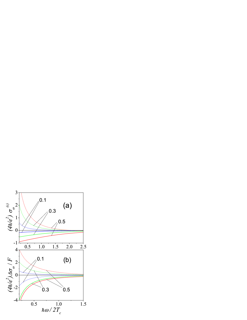
Now we examine the spectral and polarization characteristics of the electrooptical response. We study the reflection, transmission, and relative absorption coefficients, determined as , , and , respectively, 18 as well as the ellipticity degree, , for the case of weak anisotropy. The final expressions for the coefficients under consideration are obtained with the use of complex conductivities , and , given by Eqs.(7), and (8), and they depend both on , and on carriers concentration. In Fig.2. we plot these dependences and one can see that the response modify essentially with temperature and concentration. The smallness of anisotropic additions is determined by dimensionless factor
| (31) |
which arises from contribution to the distribution function (10). Note also, that depends weakly on the cutting parameter , taken below as 0.1.
III.1 Reflection and absorption
For the examination of , and it is convenient to separate the isotropic and -dependent contributions, so that
| (32) |
where the small (of the order of ) anisotropic additions, proportional to , have been separated, see Fig. 1. The coefficients in Eq. (17) are written below through , and the factor . For the isotropic parts of reflection, and relative absorption coefficiens we get 9 :
| (33) |
so that these characteristics depend on , , and .
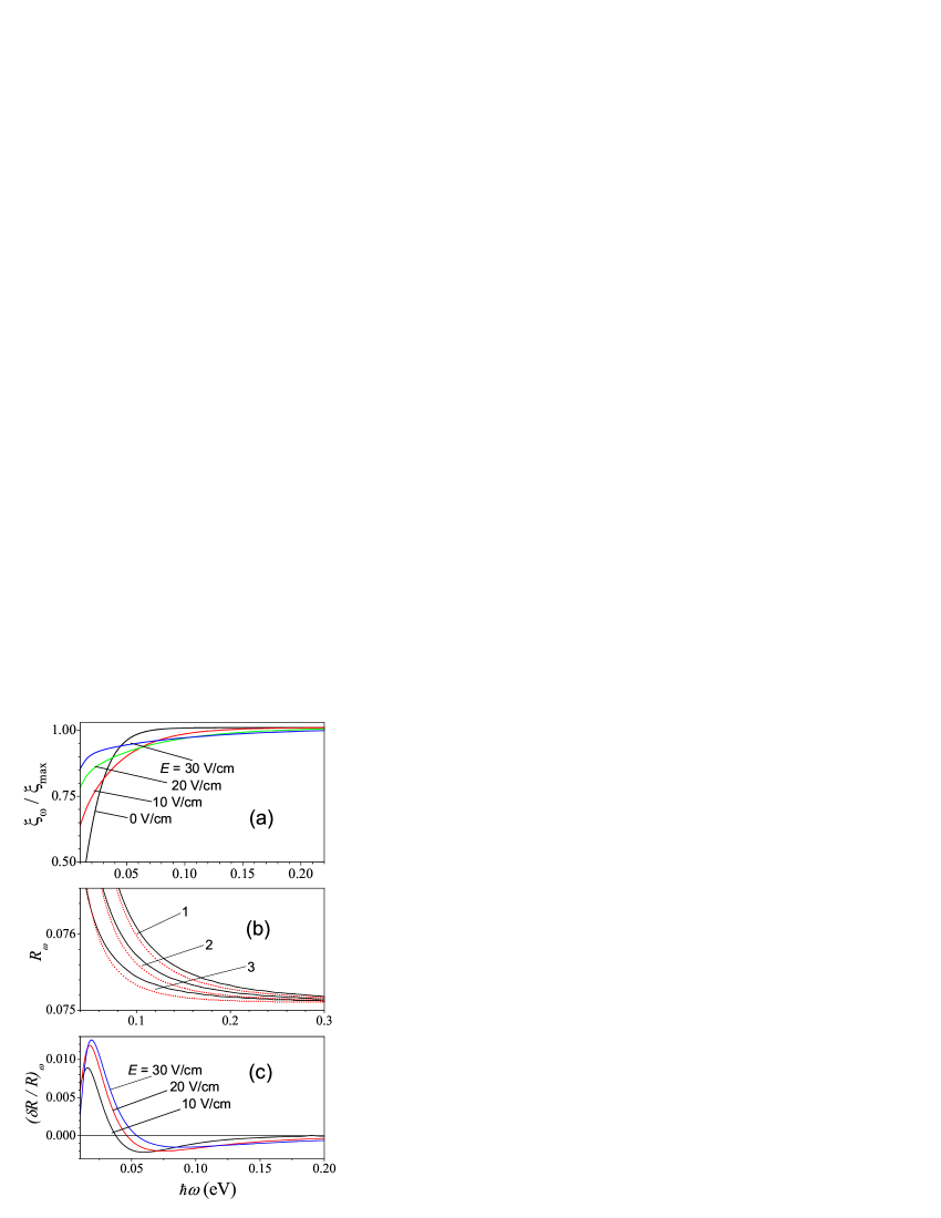
Spectral dependences of the relative absorption, , the reflection, , and the differential reflectivity , are plotted in Fig.3 for intrinsic graphene at 77 K and different electric fields (the data for and carriers concentration were used from Ref. 11). Here is the maximum value of relative absorption for high frequences, when the free carriers contribution is unessential. One can see, that due to the increase of average energy of carriers with the increase of the absorption increases at high frequencies and decreases for the low ones. The relative change of is reasonably large, and for it can be measured directly. At the same time, the reflection coefficient depends on field in more weak way, see Figs. 3b, c, and can be 10-2 in THz spectral region; in near-IR spectral region it decreases down to value . Note, that for 0.1 eV increases essentially (at high frequencies 0.075) due to the contribution of the first summand of Eq. (A2). Fig. 3b presents the dependence of on phenomenological parameter ; depends weakly on this parameter.
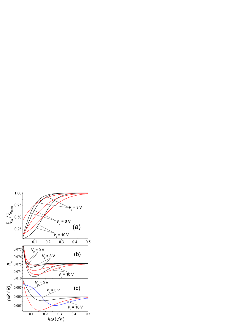
The dependences of , , and on doping level are presented in Fig.4. The data for the room temperature are presented for 3 V and 10 V, which correspond the difference between electron and hole concentrations cm-2 and cm-2, respectively. Similarly to field dependences at 77 K (see Fig.3), with the increase of (the doping level ) the response moves towards the high energy region. The dependences on the level of heating (the applied field ), and on carriers concentration (the gate voltage ) correspond the measurements of spectra for different temperatures and , see 10 . For the range of parameters under examination the field modulation of is of 2050 % order up to mid-IR spectral region. These modifications should be observed rather easily. The carriers contribution into reflection increases as well: at 0.1 eV the decrease of occurs, which almost does not depend on ; in this case the shape of the differential reflectivity is similar to low temperature case, with the shift into the high energy region.
Later we shall examine the anisotropic contributions in Eq.(17), which are proportional to . Such a contribution into reflection coefficient is given by:
| (34) |
and the addition to relative absorption takes form:
| (35) |
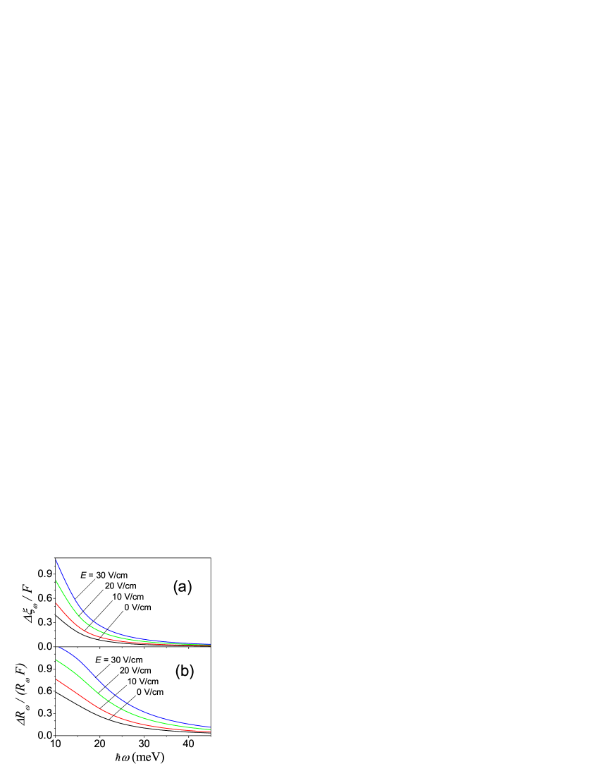
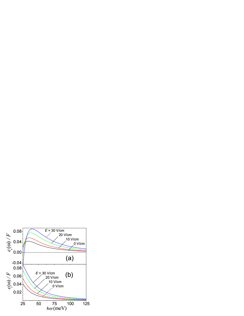
Spectral dependences for anisotropic contributions to the relative absorption and reflectivity, and , are shown in Figs. 5 (a) and (b). One can see, that in the range of fields under examination the parameter given by Eq. (16) does not exceed 0.05, so that and are of order for the mid-IR spectral region (0.2 eV) and the response increases up to in THz spectral region. The anisotropy of such order of value can be analyzed with the use of the modulation methods.
III.2 Kerr effect
Besides the cases of parallel or transverse orientation of the probe radiation polarization with respect to the drift direction (i. e. at ), the reflected and transmitted fields are elliptically polarized. The maximal Kerr effect occurs if the -wave is polarized along , and below we consider this case only. In the approximation of the weakly anisotropic distribution (2) the ellipse orientation does not differ essentially from , and the ellipticity degree can be written as 17 :
| (36) |
Here the angle, and the complex function can be expressed through the difference of the phases of -, and -waves (see the end of Sec.II). The smallness of the ellipticity is determined by the relation , while the angle is not small.
For the reflected wave the function is given by the expression
| (37) |
while the angle is introduced through the relation:
| (38) |
Similarly, for the transmitted wave, (20) is expressed through the function:
| (39) |
and the angle is given by the expression:
| (40) |
Substitution of these expressions into Eq. (21) gives the ellipticity degrees for - and -waves, and .
Spectral and field dependences of and are shown in Figs. 6a and 6b for intrinsic graphene at 300 K. In mid-IR spectral region decreases with and for 0.2 eV the value of ellipticity degree does not exceed at 0.05. In THz spectral region increases up to , wherein the direction of rotation for the reflected wave changes at 25 meV. Such value of ellipticity degree can be detected by modulation methods only. However, in stronger fields, when the distribution function is strongly anisotropic, 12 the ellipticity degree can increase essentially.
IV Conclusions
Summarizing the consideration performed, we have examined the graphene electooptical response due to the interband electron transitions under the carriers heating and drift. It was found, that an essential modulation of the reflection, and the relative absorption take place starting from the field strength 30 V/c at liquid nitrogen and room temperatures (with the increase of field, the modulation should increase essentially). Due to current-induced birefringence of graphene sheet the weak ellipticity of the reflected and transmitted radiation arise.
Next, we list and discuss the assumptions used in our calculations. First, the dynamic conductivity tensor (1) is written in collisionless approximation. For the case of short-range scattering, when , one arrives to the condition and the collisionless approximation is not valid for a strongly disordered material. Also, the interband response of a pure graphene is described with the use of the phenomenological expression (A.2) and a low-frequency restriction for this approximation is not clear.
Second, the quasiequilibrium distribution of carriers (9) was used for the numerical estimation of electrooptical response. This means the assumption of an effective intercarrier scattering. The complete description of the carriers heating under such conditions had not been performed yet 11 ; 19 . However, the approximation (9) gives a good estimation for the response magnitude, and the peculiarities of spectral dependences enable us to determine the contributions of the different relaxation mechanisms. Similarly, the use of short-range scattering model in the drift-induced contribution (10) gives the estimation for optical anisotropy magnitude, and the spectral dependences peculiarities contain information about the momentum relaxation mechanism (despite the short-range scattering can be treated as a dominant one within the phenomenological description of momentum relaxation, 16 the microscopic mechanism have not been verified until now 20 ).
Third, we have examined the heating of carriers with low energies only, (the results for 30 V/cm have been presented), when the essential electrooptical response occurs in THz spectral region only. With the increase of field (up to tens kV/cm, see 12 ) the electrooptic effect increases and shifts into near-IR spectral region. The theoretical approach developed here can be applied for this region as well, however the calculation of the distribution of hot carriers for this case have not been performed yet.
Forth, the case of graphene on a thick substrate have been examined. The consideration of the interference effects for graphene, placed on substrate of limited thickness, needs more complicated calculations (however, an accuracy of measurements can increase for near-IR spectral region [21]), and is beyond the frame of this paper. And the last, we have limited ourselves to the examination of the geometry of normal propagation of radiation only. The study of the response dependence on the angle of radiation falling gives additional experimental data, however it is more complicated and needs special treatment.
Finally, the results obtained demonstrate, that the electrooptical response due to heating and drift of carriers is large enough, and it can be measured. Because of strong dependence of the response on the applied field, temperature, and gate voltage, these measurements can give an information on relaxation and recombination mechanisms. In addition, the electrooptical response of graphene can be applied for modulation of intensity and polarization of radiation in THz and mid-IR spectral regions.
*
Appendix A Response of undoped graphene
The dynamic conductivity for the case of undoped graphene is described by Eqs. (1) and (3) after replacement of by 1 and of by 0. As a result we get the expression:
| (41) |
where the real and imaginary parts of conductivity have been separated. The direct integration with the use of the energy conservation law gives the frequency-independent real part of (A1): . The imaginary contribution into appears to be divergent at ; moreover , where is a cut-off momentum. 22 On the contrary to the case of bulk material, 9 this cut-off appears to be too rough for the description of the response in graphene. It is convenient to approximate , by separating the terms , and , which correspond the contributions of the virtual interband transitions, and of ions, correspondingly. As a result, we get:
| (42) |
where the characteristic energies, , and , have been introduced. The comparison of the response, described by , with the recent measurements of the graphene optical spectra, yields: 0.08 eV, and 6.75 eV. 15
References
- (1) M. Cardona, Modulation Spectroscopy (Academic Press, New York, 1969).
- (2) F.T. Vasko and A.V. Kuznetsov, Electron States and Optical Transitions in Semiconductor Heterostructures (Springer, New York, 1998).
- (3) L. E. Vorobev, V. G. Komissarov, V. I. Stafeev, and A. Yu. Ushakov, JETP Lett., 13 98 (1971); L. E. Vorobjev, D. V. Donetski, and D. A. Firsov, JETP Lett., 59 869 (1994).
- (4) F. T. Vasko, Sov. Phys. - Solid State 15, 1136 (1973) [Fiz. Tv. Tela 15, 1693 (1973)]; L. A. Almazov and I. M. Dykman, Phys. Stat. Sol. (b), 48, 503 (1971).
- (5) F. T. Vasko and O. E. Raichev, Quantum Kinetic Theory and Applications (Springer, New York 2005).
- (6) D. A. B. Miller, D. S. Chemla, T. C. Damen, A. C. Gossard, W. Wiegmann, T. H. Wood, and C. A. Burrus, Phys. Rev. B 32, 1043 (1985); A. Fainstein, P. Etchegoin, P. V. Santos, M. Cardona, K. Totemeyer, and K. Eberl, Phys. Rev. B 50, 11850 (1994); L. E. Vorobev, D. A. Firsov, V. A. Shalygin and I. I. Saidashev, JETP Lett. 65, 549 (1997).
- (7) A.H. Castro Neto, F. Guinea, N.M.R. Peres, K.S. Novoselov, and A.K. Geim, Rev. Mod. Phys. 81, 109 (2009).
- (8) P.R. Wallace, Phys. Rev. 71, 622 (1947); E.M. Lifshitz, L.P. Pitaevskii, and V.B. Berestetskii, Quantum Electrodynamics (Butterworth-Heinemann, 1982).
- (9) L.A. Falkovsky, Phys. Usp. 51, 887 (2008); T. Stauber, N. M. R. Peres, and A. K. Geim, Phys. Rev. B78, 085432 (2008).
- (10) F. Wang, Y. Zhang, C. Tian, C. Girit, A. Zettl, M. Crommie, Y. R. Shen, Science, 320, 206 (2008); R. R. Nair, P. Blake, A. N. Grigorenko, K. S. Novoselov, T. J. Booth, T. Stauber, N. M. R. Peres, and A. K. Geim, Science 320, 1308 (2008); K. F. Mak, M. Y. Sfeir, Y. Wu, C. H. Lui, J. A. Misewich, and T. F. Heinz, Phys. Rev. Lett. 101, 196405 (2008).
- (11) O. G. Balev, F. T. Vasko and V. Ryzhii, Phys. Rev. B 79, 165432 (2009).
- (12) J. Moser, A. Barreiro, and A. Bachtold, Appl. Phys. Lett. 91, 163513 (2007); I. Meric, M. Y. Han, A. F. Yang, B. Ozyilmaz, P. Kim, and K. L. Shepard, Nature Nanotech. 3, 654 (2008); A. Barreiro, M. Lazzeri, J. Moser, F. Mauri, and A. Bachtold, Phys. Rev. Lett. 103, 076601 (2009).
- (13) O.G. Balev and F.T. Vasko, submitted.
- (14) T.S. Moss, G.J. Burrel, and A. Hetherington, Proc. Roy. Soc. A308, 125 (1968); L.A. Almazov, F.T. Vasko, and I.M. Dykman, JETP Lett. 16, 214 (1972); L. E. Vorobjev, D. V. Donetskii, D. A. Firsov, JETP Lett., 71 331 (2000).
- (15) M. Bruna and S. Borini, Appl. Phys. Lett. 94 031901 (2009).
- (16) F.T. Vasko and V. Ryzhii, Phys. Rev. B 76, 233404 (2007).
- (17) M. Born and E. Wolf, Principles of Optics (Pergamon Press Ltd., London, 1980).
- (18) According to Eq. (15), the reflection, transmission, and relative absorption coefficients are connected by the relation: .
- (19) A. Akturka and N. Goldsman, J. Appl. Phys. 103, 053702 (2008); R. S. Shishir and D. K. Ferry, J. Phys.: Condens. Matter, 21, 344201 (2009).
- (20) T.M. Mohiuddin, L.A. Ponomarenko, R. Yang, S.M. Morozov, A.A. Zhukov, F. Schedin, E.W. Hill, K.S. Novoselov, M.I. Katsnelson, and A. K. Geim, Phys. Rev. Lett. 102, 206603 (2009); S. Adam, P.W. Brouwer, and S. Das Sarma, Phys. Rev. B 79, 201404 (2009).
- (21) P. Blake, K. S. Novoselov, A. H. Castro Neto, D. Jiang, R. Yang, T. J. Booth, A. K. Geim, and E. W. Hill, Appl. Phys. Lett. 91, 063124 (2007); D. S. L. Abergel, A. Russell, and V. I. Fal ko, Appl. Phys. Lett. 91, 063125 (2007); V. Yu, M. Hilke, Appl. Phys. Lett. 95, 151904 (2009).
- (22) A. Principi, M. Polini, and G. Vignale,Phys. Rev. B 80, 075418 (2009); M. Polini, A.H. MacDonald, and G. Vignale, arXiv:0901.4528.