Terahertz and Infrared Photodetection using p-i-n Multiple-Graphene-Layer Structures
Abstract
We propose to utilize multiple-graphene-layer structures with lateral p-i-n junctions for terahertz (THz) and infrared (IR) photodetection and substantiate the operation of photodetectors based on these structures. Using the developed device model, we calculate the detector dc responsivity and detectivity as functions of the number of graphene layers and geometrical parameters and show that the dc responsivity and detectivity can be fairly large, particularly, at the lower end of the THz range at room temperatures. Due to relatively high quantum efficiency and low thermogeneration rate, the photodetectors under consideration can substantially surpass other THz and IR detectors. Calculations of the detector responsivity as a function of modulation frequency of THz and IR radiation demonstrate that the proposed photodetectors are very fast and can operate at the modulation frequency of several tens of GHz.
I Introduction
Unique properties of graphene layers (GLs) 1 ; 2 ; 3 make them promising for different nanoelectronic device applications. The gapless energy spectrum of GLs, which is an obstacle for creating transistor-based digital circuits, opens up prospects to use GLs in terahertz (THz) and infrared (IR) devices. Novel optoelectronic THz and IR devices were proposed and evaluated, in particular, in Refs. 4 ; 5 ; 6 ; 7 ; 8 ; 9 ; 10 ; 11 . Recent success in fabricating multiple-GL structures with long momentum relaxation time of electrons and holes 12 promises a significant enhancement of the performance of futures graphene optoelectronic devices 13 .
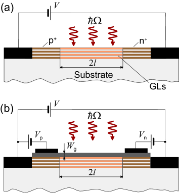
In this paper, we study the operation of THz and IR photodetectors based on multiple-GL structures with p-i-n junctions. We refer to the photodetectors in question as to GL-photodetectors (GLPDs). We focus on GLPDs with - and -doped sections in GLs near the side contacts 14 ; 15 , p+ and n+ contacts (for example, made of doped poly-Si 16 ), and multiple GL-structures with the Ohmic side contacts and split-gates which provide the formation of the electrically induced p- and n-sections 17 ; 18 ; 19 ; 20 ; 21 ; 22 . The device structures under considerations are shown in Figs. 1(a) and 1(b). It is assumed that the highly-conducting GL(s) between the SiC substrate and the top GLs is removed. Multiple GL-structures without this highly conducting GL can be fabricated using chemical/mechanical reactions and transferred substrate techniques (chemically etching the substrate and the highly conducting bottom GL 23 or mechanically peeling the upper GLs, then transferring the upper portion of the multiple-GL structure on a Si substrate).
Using the developed device model, we calculate the GLPD responsivity and detectivity as THz or IR photodetector (Secs. II and III), evaluate its dynamic response (Sec. IV), and compare GLPDs with some other THz and IR photodetectors (Sec. V), in particular, with quantum-well infrared photodetectors (QWIPs) and quantum-dot infrared photodetectors (QDIPs). In Sec. VI, we discuss possible role of the Pauli blocking in the spectral characteristics of GLPDs and draw main conclusions. The calculations related to the effect of screening of the vertical electric field on the formation of the electrically induced p- and n-sections in multiple-GL structures are singled out in the Appendix.
II Responsivity and detectivity
We assume that the intensity of the incident THz or IR radiation with the frequency apart from the dc component includes the ac component: , where and are the amplitude of the latter component and its modulation frequency, respectively. In such a situation, the net dc current (per unit width of the device in the direction perpendicular to the current) can be presented in the following form:
| (1) |
with
| (2) |
and
| (3) |
Here is the electron charge, is the number of GLs, is the length of the GL’s i-section, and are the rates of thermal and tunneling generation of the electron-hole pairs (per unit area) 22 , is the bias voltage, cm/s is the characteristic velocity of electrons and holes in graphene, is the absorption coefficient of radiation in a GL due to the interband transitions 24 , where , is the distribution function of electrons and holes in the i-section, is the Planck constant, and is the speed of light. The term in Eq. (2) is associated with the interband tunneling in the electric field in the i-section. The quantity is the intensity of THz or IR radiation at the -th GL ().
At a sufficiently strong reverse bias, electrons and holes are effectively swept out from the i-section to the contacts and heated. Due to this, one can assume that under the GLPD operation conditions, , so that the distinction between and can be disregarded (see below).
Using Eqs. (1) and (3), we arrive at the following formula for the GLPD dc responsivity:
| (4) |
where . Equation (4) can also be rewritten as
| (5) |
If , Eq. (5) at THz, yields, A/W. For (), setting , in the frequency range THz, from Eq.(4) we obtain A/W.
The dark-current limited detectivity, , defined as , where is the noise (in Amperes), is the power received by the photodetector (in Watts), is the area of the photodetector (in cm2)(see, for instance, 25 ; 26 ), and is the bandwidth, can be expressed via the responsivity and the dark current , where is the device width in the direction perpendicular to the current, can be presented as
| (6) |
Using Eqs. (2) - (6), we arrive at
| (7) |
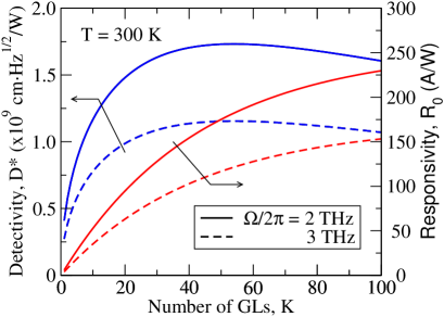
Assuming that and cm-2s-1 27 , at K for THz we obtain cmHz1/2/W. Setting , we arrive at cmHz1/2/W. Due to a significant decrease in the thermogeneration rate at lower temperatures, the detectivity markedly increases with decreasing temperature. Indeed, at K, setting cm-2s-1 27 , we obtain cmHz1/2/W.
Figure 2 shows the dependences of the dc responsivity and detectivity on the number of GLs calculated for THz using Eqs. (5) and (7) for GLPDs with sufficiently large in which the tunneling is weak (see below).
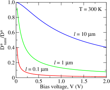
Equation (7) shows that the GLPD detectivity decreases with increasing photon frequency. This is because the spectral dependence of the GLPD detectivity is determined by that of the responsivity. As follows from Eqs. (6) and (7), the detectivity drops at elevated bias voltages when the interband tunneling prevails over their thermogeneration of the electron and hole pairs. According to Eqs. (4) and (7), the GLPD responsivity is independent of the length of the i-section and the bias voltage (at least if the latter is not too small), whereas the detectivity increases with increasing and decreases with . This is because the component of the dark current associated with the thermogeneration rate increases linearly with increasing . At the same time, the tunneling component is proportional to . As a result, from Eq. (7) one can arrive at
| (8) |
where . Thus, at elevated bias voltages when the tunneling generation surpassed the thermal generation, . Figure 3 shows the voltage-dependence of the detectivity with the interband tunneling normalized by the detectivity without tunneling calculated for different values of the i-section length .
Since the value of is determined by both and , the latter values should be properly chosen.
There is also a limitation associated with the necessity to satisfy the condition , where is the recombination length. Otherwise, the recombination in the i-section can become essential resulting in degrading of the GLPD performance. The recombination length can be defined as , where , is the recombination time, and is the average drift velocity in the i-region. Assuming that for the electron and hole densities close to that in the intrinsic graphene at K one can put s. Setting for sufficiently large bias cm/s 28 , one can find m.
III Features of GLPD with electrically-induced junction
The main distinctions of the detectors with doped and electrically induced p-i-n-junction are that the Fermi energies of electrons and holes in the latter depend on the gate voltages in the p-section and in the n-section [see Fig. 1(b)] and that these energies and, hence, the heights of the barriers confining electrons and holes in the pertinent section are different in different GLs. This is due to the screening of the transverse electric field created by the gate voltages by the GL charges. This screening results in a marked decrease in the barrier heights of the GLs located in the MGL-structure depth (with large indices ) in comparison with the GLs near the top. In the following, we set . The barriers in question effectively prevent the electron and hole injection from the contacts under the reverse bias if the barrier heights are sufficiently large. However, the electron and hole injection into the GLs with large leads to a significant increase in the dark current (in addition to the current of the electrons and hole generated in the i-section). This can substantially deteriorate the GLPD detectivity. As for the responsivity, it can still be calculated using Eqs. (4) or (5). To preserve sufficiently high detectivity, the number of GLs should not be too large. Indeed, taking into account the contributions of the current injected from the p- and n-regions to the net dark current, the detectivity of a GLPD with the electrically-induced p-i-n junction can be presented as
| (9) |
where is the electron current injected from the p-region and the hole current injected from the n-region, is the Fermi energy of holes (electrons) in the p-region (n-region) of the -th GL ().
The injected currents are small in comparison with the current of the electrons and holes thermogenerated in the i-region if
| (10) |
Here is the electron and hole density in the intrinsic graphene (at given temperature).
Considering Eqs. (A5) and (A6) from the Appendix, the latter imposes the following limitation on the number of GLs in GLDs with the electrically-induced p-i-n junctions and the gate voltage :
| (11) |
The quantity is defined in the Appendix. For , assuming that the Fermi energy in the topmost GL meV, K, cm-2, m, and cm-2s-1, we obtain , i.e., fairly large. A decrease in results in smaller due to a substantial increase in the tunneling current. For instance, if m 11 , we obtain .
Thus, by applying gate voltages one can form the p- and n-sections with sufficiently high densities and large Fermi energies of holes and electrons in GL-structures with a large number of GLs.
IV Dynamical response
To describe the dynamic response to the signals modulated with the frequency , one needs to find the ac components of the net density of photogenerated electron and holes, and , respectively. These components are governed by the following equation:
| (12) |
As in above, , so that
In the case of ballistic transport of electrons and holes across the i-section, . If the electron and hole transport is substantially affected by quasi-elastic scattering, so that the momentum distributions of electrons and holes are virtually semi-isotropic, one can put (see also, Ref. 28 ). Solving Eq. (12) with the boundary conditions , we obtain
| (13) |
Using Eq. (13) and considering the Ramo-Shockley theorem 28 ; 29 applied to the case of specific contact geometry 30 the ac current induced in the side contacts (terminal current), can be presented as
| (14) |
Here we have introduced the characteristic transit time . The feature of the contact geometry (the blade-like contacts) was accounted for by using the form-factor 31 . This is valid because the thickness of the side contacts and multiple-GL structure under consideration even at rather large numbers of GLs , where is the spacing between GLs. Similar approach was used previously to analyze the dynamic response of the lateral junction photodiodes made of the standard semiconductors 32 and the graphene tunneling transit-time THz oscillator 22 . Integrating in Eq. (14), we arrive at the following:
| (15) |
where is the Bessel function. Equation (15) yields
| (16) |
Using Eq. (16), for the frequency dependent responsivity , we obtain
| (17) |

Figure 3 shows the responsivity normalized by its dc value versus the modulation frequency calculated using Eq. (17) for different values of the transit time . At cm/s, the range ps corresponds to the length of the i-section m. As seen from Fig. 3, when the modulation cut-off frequency GHz. Naturally, in GLPDs with shorter i-sections, can be markedly larger (although, at the expense of a substantial increase in the tunneling current). Due to this, GLPDs can be used as ultrafast THz and IR photodetectors.
V Comparison with QWIPs and QDIPs
Now we compare the responsivity and detectivity of GLPDs with GLs calculated above and those of QWIPs (properly coupled with the incident THz or IR radiation) and QDIPs with the same number of QWs. The fraction of the absorbed photon flux in one QW , where is the cross-section of the photon absorption due to the intersubband transitions and the donor sheet density. Setting the usual values cm2 and cm-2, one obtains . This value is one order of magnitude smaller that . Hence, one can neglect the attenuation of radiation in QWIPs with (whereas in GLPDs it can be essential) . In such a case, the responsivity of QWIPs is independent of the number of QWs in the QWIP structure 33 and given by
| (18) |
where is the so-called capture probability which relates to the QWIP gain as 33 . Using Eqs. (4) and (18), we obtain
| (19) |
Assuming that , (), and , we obtain .
The ratio of the detectivities can be presented as
| (20) |
As can be extracted from Ref. 26 , , where eV is the energy of optical phonon in GLs, whereas , where is the QW ionization energy (), Eq. (17) yields
| (21) |
Different dependences of the responsivities and detectivities of GLDs and QWIPs on is due different directions of the dark current and photocurrent: parallel to the GL plane in the former case and perpendicular to the QW plane in the latter case. The product of the factors in the right-hand side of Eq. (21) except the last one can be on the order of unity. This is because a large ratio can be compensated by relatively small capture parameter . However, the exponential factor in Eq. (21) is large in the THz range: , i.e., at THz. In particular, at K and THz, the exponential factor in question is about 24 - 36.
The GLPD responsivity and detectivity can also markedly exceed those of QDIPs (for which formulas similar to Eqs. (21) and (22) can be used) despite lower capture probability and thermoexcitation rate in QDIPs in comparison with QWIPs (see, for instance, Refs. 34 ; 35 ; 36 . The ratios and dramatically increases with decreasing and . This is attributed to the fact that the spectral dependence of the GLPDs detectivity is similar to the spectral dependence of the responsivity (), whereas the GLPDs intended for the photodetection in different spectral ranges exhibit the same dark current (due to the gapless energy spectrum). In contrast, in QWIPs, QDIPs, and some other photodetectors (see, for example, Refs. 9 ; 10 ) the transition to lower photon frequency requires to utilize the structures with lower ionization energy and, hence, exponentially higher dark current. The latter leads to quite different spectral dependencies of the GLPD detectivity and the detectivity of QWIPs and QDIPs (which drops with increasing photon freqiency).
GLPDs can surpuss QWIPs and QDIPs in responsivity even at relatively high photon frequencies. For example, for a GLPD with at THz (wavelength about m), we arrive at A/W. This value is three times larger than obtained experimentally for a QDIP with 25 InAs QD layers 37 . As for the detectivity, comparing a GLPD with operating at K and THz (m) and a QDIP with 70 QD layers 38 , we obtain cmHz1/2/W and cmHz1/2/W, respectively.
GLPDs can surpass also photodetectors on narrow-gap and gapless bulk semiconductors like HgCdTe (BSPDs). Apart from advantages associated with potentially simpler fabrication, GLPDs might exhibit higher detectivity (compare the data above and those from Ref. 39 ). This can be attributed to relatively low thermogeneration rate in GLPDs compared to BSPDs with very narrow or zeroth gap. The point is that thermogeneration rate in GLPDs at room temperatures is primarily due absorption of optical phonons 27 which have fairly large energy (the Auger processes in GLs are forbidden 40 ), whereas this rate in BSPDs is essentially determined by the Auger processes which are strong 39 .
VI Discussion and conclusions
Analyzing Eqs. (4) - (7), we accepted that and, therefore, disregarded the frequency dependence of the absorption coefficient associated with the population of the low energy states by electrons and holes. For a rough estimate, the value of distribution function can be presented as , where is the electron and hole density in the i-section under the reverse bias. This density, in turn, can be estimated as . Using the same parameters as above, for m and K, we obtain , so that and . It implies that the numerical data obtained above for the frequencies at the lower end of the THz range might be slightly overestimated. However, since the electron-hole system in the i-section can be pronouncedly heated by the electric field, the actual values of can be smaller than in the latter estimate and, hence, can be rather close to . The electron and hole heating in intrinsic GLs under the electric field was studied recently 28 ; 41 . In contrast to the cases considered in Refs. 28 ; 41 , the finiteness of the transit time of electrons and holes in the i-section of the GL-structures under consideration strongly affects the electron and hole heating. Therefore, more careful calculation of at relatively low requires separate consideration.
In summary, we proposed and evaluated GLPDs multiple-GL p-i-n structures. It was shown that GLPDs can exhibit high responsivity and detectivity in the THz and IR ranges at room temperatures. Due to relatively high quantum efficiency and low thermogeneration rate, the GLPD responsivity and detectivity can substantially exceed those of other photodetectors.
Acknowledgments
The authors are grateful to M. S. Shur, A. A. Dubinov, V. V. Popov, A. Satou, M. Suemitsu, and F. T. Vasko for fruitful discussions and comments. This work was supported by the Japan Science and Technology Agency, CREST, Japan.
References
- (1) C. Berger, Z. Song, T. Li, X. Li, A.Y. Ogbazhi, R. Feng, Z. Dai, A. N. Marchenkov, E. H. Conrad, P. N. First, and W. A. de Heer, J. Phys. Chem. 108, 19912 (2004).
- (2) K. S. Novoselov, A. K. Geim, S. V. Morozov, D. Jiang, M. I. Katsnelson, I. V. Grigorieva, S. V. Dubonos, and A. A. Firsov, Nature 438, 197 (2005).
- (3) A. H. Castro Neto, F. Guinea, N. M. R. Peres, K. S. Novoselov, and A. K. Geim, Rev. Mod. Phys. 81 109 (2009).
- (4) F. T. Vasko and V. Ryzhii Phys. Rev. B 77, 195433 (2008).
- (5) V. Ryzhii, M. Ryzhii, and T. Otsuji, J. Appl. Phys. 101, 083114, (2007).
- (6) F. Rana, IEEE Trans. Nanotechnol. 7, 91 (2008).
- (7) A. Satou, F. T. Vasko, and V. Ryzhii, Phys. Rev. B 78, 115431 (2008).
- (8) A. A. Dubinov, V. Ya. Aleshkin, M. Ryzhii, T. Otsuji, and V. Ryzhii, Appl. Phys. Express 2, 092301 (2009).
- (9) V. Ryzhii, V. Mitin, M. Ryzhii, N. Ryabova, and T. Otsuji, Appl. Phys. Express 1, 063002 (2008).
- (10) V. Ryzhii and M. Ryzhii, Phys. Rev. B 79, 245311 (2009).
- (11) F. Xia, T. Murller, Y-M. Lin, A. Valdes-Garsia, and F. Avouris, Nature Nanotecnology, in press (2009).
- (12) P. Neugebauer, M. Orlita, C. Faugeras, A.-L. Barra, and M. Potemski, Phys. Rev. Lett. 103, 136403 (2009).
- (13) V. Ryzhii, M. Ryzhii, A. Satou, T. Otsuji, A. A. Dubinov, and V. Ya. Aleshkin, J. Appl. Phys. 106, 084507 (2009)
- (14) Yu-M. Lin, D. B. Farmer, G. S. Tulevski, S. Xu, R. G. Gordon, and P. Avouris, Device Research Conf. Tech. Dig., p. 27, Santa Barbara, USA, 2008.
- (15) D. Wei, Y. Liu, Y. Wang, H. Zhang, L. Huang, and G. Yu, Nano Lett. 9 1752 (2009).
- (16) J. Zhu and J. C. S. Woo, Ext. Abstracts of the 2009 Int. Conf. on Solid State Devices and Materials, p. G-9-2 Sendai, 2009.
- (17) V. V. Cheianov and V. I. Fal’ko, Phys. Rev. B 74, 041403(R) (2006).
- (18) L. M. Zhang and M. M. Fogler, Phys. Rev. Lett. 100, 116804 (2008).
- (19) B. Huard, J. A. Sulpizio, N. Stander, K. Todd, B. Yang, and D. Goldhaber-Gordon Phys. Rev. Lett. 98, 236803 (2007).
- (20) B. Ozyilmaz, P. Jarillo-Herrero, D. Efetov, D. Abanin, L. S. Levitov, and P. Kim, Phys. Rev. Lett. 99, 166804 (2007).
- (21) M. Ryzhii and V. Ryzhii, Jpn. J. Appl. Phys. 46, L151 (2007).
- (22) V. Ryzhii, M. Ryzhii, V. Mitin, and M. S. Shur, Appl. Phys. Express 2, 034503 (2009).
- (23) A. Bostwick, T. Ohta, T. Seyller, K. Horn, and E. Rotenberg, Nature Phys. 3, 36 (2007).
- (24) L. A. Falkovsky and A. A. Varlamov, Eur. Phys. J. B 56, 281 (2007)
- (25) A. Rose, Concepts in Photoconductivity and Allied Problems (Wiley, New York, 1963).
- (26) M. Razeghi, Ed. Long Wavelength Infrared Detectors, (Gordon and Breach, Amsterdam, 1996).
- (27) F. Rana, P. A. George, J. H. Strait, S. Shivaraman, M. Chanrashekhar, M. G. Spencer, Phys. Rev. B 79, 115447 (2009).
- (28) R. S. Shishir, D. K. Ferry, and S. M. Goodnick, J. Phys.: Conf. Ser 193, 012118 (2009).
- (29) S. Ramo, Proc. IRE 27, 584 (1939).
- (30) C. K. Jen, Proc. IRE 29, 345 (1941).
- (31) V. Ryzhii and G. Khrenov, IEEE Trans. Electron Devices, 42, 166 (1995).
- (32) N. Tsutsui, V. Ryzhii, I. Khmyrova, P. O. Vaccaro, H. Taniyama, and T. Aida, IEEE J. Quant. Electron. 37, 830 (2001).
- (33) H. Schneider and H. C. Liu, Quantum Well Infrared Photodetectors, (Springer, Berlin, 2007).
- (34) V. Ryzhii, Semicond. Sci. Technol. 11, 759, (1996).
- (35) V. Ryzhii, I. Khmyrova, M. Ryzhii, and V. Mitin, Semicond. Sci. Technol. 19, 8 (2004).
- (36) A. Rogalski, J. Antoszewski, and L. Faraone, J. Appl. Phys. 105 091101 (2009).
- (37) H. Lim. S. Tsao, W. Zhang, and M. Razeghi, Appl. Phys. Lett. 90, 131112 (2007).
- (38) S. Chakrabarti, A. D. Siff-Roberts, X. H. Su, P. Bhattacharya, G. Ariyawansa, and A. G. U. Perera, J. Phys. D: Appl. Phys. 38, 2135 (2005).
- (39) P. Martyniuk, S. Krishna, and A. Rogalski, J. Appl. Phys. 104, 034314 (2008).
- (40) M. S. Foster and I. L. Aleiner, Phys. Rev.B 79, 085415 (2009).
- (41) O. G. Balev, F. T. Vasko, and V. Ryzhii, Phys. Rev. B 79, 165432 (2009).
Appendix. Effect of vertical screening in multiple GL-structures
As was pointed out above, the thickness of multiple GL-structures even with rather large number of GLs is in reality small in comparison with the lateral sizes of the device, namely, the lengths of all the section and, hence, the gates. Owing to this, the distribution of the dc electric potential normalized by (where ) in the direction perpendicular to the GL plane (corresponding to the axis ) can be found from the one-dimensional Poisson equation:
| (A1) |
Here is the electron (hole) density in the -th GL in the n-section (p-section), is the spacing between GLs, and is the Dirac delta-function. Considering that , where is the Fermi energy in the -section (-section) of the -th GL, and replacing the summation in Eq. (A1) by integration (that is valid if is not too small), we reduce Eq. (A1) to the following:
| (A2) |
with the characteristic screening length . One can assume that and (as well as ), where is the thickness of the layer separating the multiple GL-structure and the gates. Solving Eq. (A2) with the latter boundary conditions, we arrive at
| (A3) |
where satisfies the following equation:
| (A4) |
Since in reality , from Eq. (A4) one obtains Setting nm, nm, , and V, one can obtain nm, and .
Equation (A3) yields
| (A5) |
Here is the Fermi energy of electrons in the topmost GL in the n-section (holes in the p-section) and
| (A6) |
where At the above parameters (in particular, nm and V) .