Polarization conversion spectroscopy of hybrid modes
Abstract
Enhanced polarization conversion in reflection for the Otto and Kretschmann configurations is introduced as a new method for hybrid-mode spectroscopy. Polarization conversion in reflection appears when hybrid-modes are excited in a guiding structure composed of at least one anisotropic media. In contrast to a dark dip, in this case modes are associated to a peak in the converted reflectance spectrum, increasing the detection sensitivity and avoiding confusion with reflection dips associated with other processes as can be transmission.
Waves incident onto the surface of an anisotropic medium can get reflected with a polarization orthogonal to the incident one reflection_CM91 . In natural crystals, this conversion of polarization states is small for incidence below the critical angle polariz_CM92 and increases under total reflection conditions critang_JMO93 . Total conversion has been predicted in corrugated structures sinusoidal_PRB94 and in metallic interfaces supporting plasmons Bryan-Brown90 ; Kats05 ; plasmon09 . Structures using anisotropic thin films have shown an enhancement of this polarization conversion thinfilm_OC06 . Importantly, similar structures can support different kinds of hybrid guided modes. A special case corresponds to surface waves (SWs) supported at the interfaces between anisotropic and isotropic media D'yakonov88 . These SWs, referred to as Dyakonov SWs, are hybrid waves existing under special conditions, which have been recently observed thanks to the presence of the polarization conversion effect in the Otto-Kretschmann excitation scheme Takayama09 . Under this scheme, the usual dip in a bright background observed in reflection (conserving polarization) was substituted by a bright-peak in a dark background for the orthogonal polarization. Additionally, reflection dips which are not associated to modes of the structure, as can be transmission, did not result in a peak in the polarization converted image. This provided a higher contrast and specificity, making possible the observation of Dyakonov SWs.
In addition to increasing contrast, the results in Ref.plasmon09 ; thinfilm_OC06 ; Takayama09 suggest that, in the Otto-Kretschmann configuration, the hybrid nature of any existing mode is related to the enhanced polarization conversion effect. The aim of this paper is to theoretically demonstrate that the mode excitation is related to polarization conversion, which can be used as a new method for hybrid mode spectroscopy.
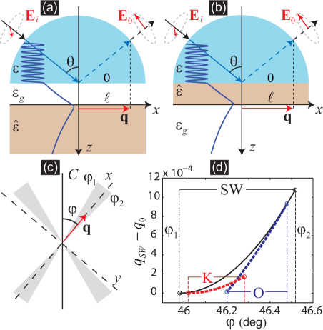
Consider a plane arbitrarily-polarized monochromatic wave with the wavevector incident from a prism with dielectric permittivity onto a uniaxial crystal characterized by a dielectric tensor with longitudinal, , and orthogonal, , components. The Otto (O) geometry is achieved when the uniaxial crystal is separated from the prism by a dielectric medium (gap), with width and permittivity [Fig. 1(a)]. The Kretschmann (K) geometry is obtained when the crystal with thickness is sandwiched between the prism and the dielectric medium [Fig. 1(b)]. The laboratory axes are chosen so that the axis is orthogonal to the media interfaces and the axis is oriented an angle relatively to the optic axis of the crystal. The interface of the prism coincides with the plane. The electric field in the prism is written in a compact form as
| (1) |
Here specifies the polarization. The index “” is related to the incident wave. are the polarization amplitudes of the incident wave and “” stays for the reflected one; are the reflection coefficients (RCs). The polarization vectors are and , where is the dimensionless wavevector component parallel to the interface, and . In the laboratory coordinate system , being the incident angle. The fields inside the isotropic gap (in the case of the O geometry) and inside the substrate (for the K geometry) are decomposed using the same polarization basis. Inside the crystal the unit vectors for the extraordinary and ordinary waves are and respectively. The -components of the dimensionless wavevectors , where specifies the medium, are , , , . The sign choice depends upon the propagation direction of the corresponding wave.
Matching the tangential components of the fields at the boundaries and , we arrive at the system of linear equations for the unknown RCs. Then the eigen modes of the system are the solutions of the homogeneous system of equations, when . The modes dispersion relation is obtained from the zeros of the determinant of the system. These equations reduce to the solution for the surface waves studied by Dyakonov D'yakonov88 in the limit . Recall that these hybrid SWs (with purely imaginary , , and for the given ) exist in a certain range of angles under the condition [Fig. 1(c,d)]. An incident wave from one of the half-spaces cannot couple to the SW directly since the phase velocity of the SW is less than that of the incident wave. The O and K configurations solve the problem by adding a prism with . Now, the radiation leakage is added to the SW and the wave incident from the prism at angles exceeding the total internal reflection one, , can couple to the SW [Fig. 1(a,b)]. However, the radiation leakage restricts the angular interval of the SW existence. For the O configuration the dispersion curve is mainly cut from the lower angles, while for the K geometry the curve is cut from the higher angles.
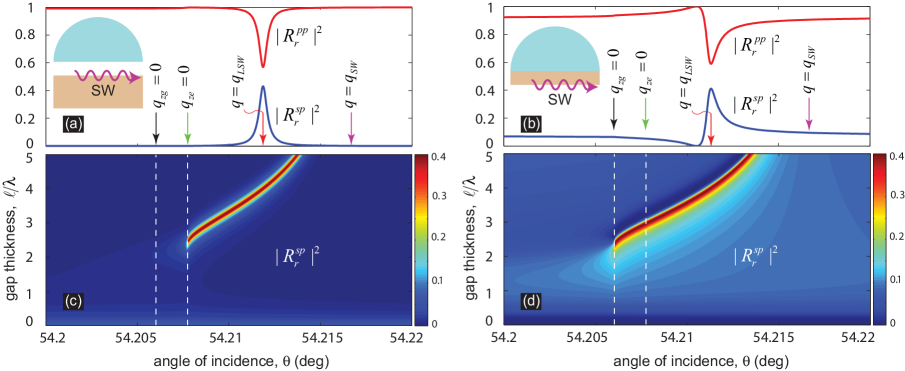
Returning to the inhomogeneous case, we would like to emphasize that, as follows directly from the system of equations, and when the fields are evanescent both in the isotropic media and in the crystal. Thus, the reflection of the plane wave is symmetric relative to the polarizations of the incident and reflected waves. An example of the SW excitation for a YVO4 crystal is shown in Fig. 2. For this crystal, and using Ta2O5 as the isotropic medium, the pure Dyakonov SW exists in the angular range . The vertical arrows both in (a) and (b) indicate the positions of the angle for the pure Dyakonov SW (), leaky Dyakonov SW () and the branch points for both the extraordinary wave, , and the isotropic medium, . The branch point of the ordinary wave, , is far below the interval of incident angles shown in the figure. The spectral position of the leaky Dyakonov SW virtually coincides with the angle of RCs maximum, where enhanced polarization conversion takes place [Fig. 2 (a,b)]. The width of the resonance curve depends upon the gap thickness as shown in Fig. 2 (c,d). For each fixed there is an optimal value of corresponding to the best compromise between coupling strength and radiation leakage. Interestingly, when increases, the required angle of incidence evolves towards the value corresponding to the pure Dyakonov SW, demonstrating that polarization conversion is related to the hybrid mode in the structure.
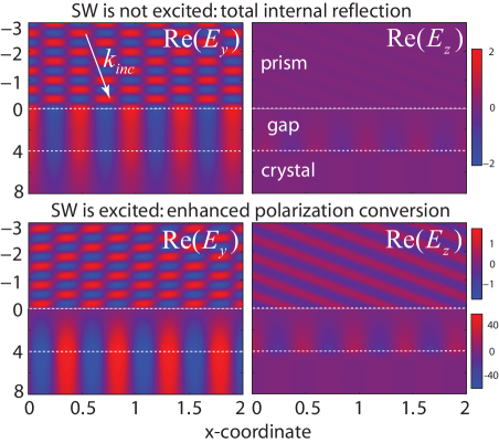
The transformation process and excitation of the SW can be visually demonstrated by plotting the instant spatial field distribution (Fig. 3). In this figure we show two projections of the electric field when the incident wave is -polarized (incident field with -component only) in the O configuration. The two upper insets show the nonresonant case, when the SW is not excited. Here a strong internal reflection takes place, resulting in an interference pattern for the component. In this case, which does not show polarization conversion, all the fields below the prism are evanescent and inside the crystal they are distributed between the ordinary and extraordinary components. Under the resonant conditions, shown in two lower insets, the increase of the field amplitude at the boundary between the crystal and the gap demonstrates the excitation of the SW. This is connected with a reduction in the -component of the reflected wave (resulting in a lower contrast interference pattern) that is converted into the orthogonal polarization, leading to a strong reflection in component.
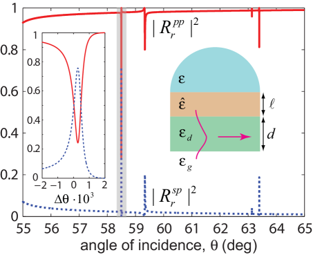
The central point of this Letter is that polarization conversion spectroscopy is not only restricted to Dyakonov surface waves, but to other structures supporting hybrid modes. For example, Fig. 4 shows polarization conversion for the simpler case of a waveguide, where four peaks corresponding to the two first transversal electric (TE)- and transversal magnetic (TM)-dominant hybrid modes are clearly shown. Polarization conversion has also been experimentally observed in a more complex situation involving metals plasmon09 , where the excited plasmon was a hybrid SW which was mainly a TM modemihalache94 .
These results demonstrate the link between excitation of hybrid modes and enhanced polarization conversion in Otto-Kretschmann geometries. However, note that analogous resonance effects take place when hybrid modes are excited not using a prism but by a periodical structure formed on the surface of the crystal. In that case the polarization conversion can be observed both in the zero and higher diffraction orders. As a result, polarization conversion can be used in all these configurations as a new hybrid-mode spectroscopic method.
The authors acknowledge financial support from the Spanish Ministry of Science under projects No. MAT2009-06609-C02, No. CSD2007-046-Nanolight.es and Spanish MCyT project FIS2006-10045. A.Y.N. acknowledges MICINN for Juan de la Cierva Grant.
References
- (1) J. Lekner, “Reflection and refraction by uniaxial crystals” J. Phys. Cond. Mat. 3, 6121 (1991).
- (2) J. Lekner, “Bounds and zeros in reflection and refraction by uniaxial crystals” J. Phys. Cond. Mat. 4, 9459 (1992).
- (3) F. Yang and J. R. Sambles, “Critical angles for reflectivity at an isotropic anisotropic boundary” J. Mod. Opt. 40, 1131 (1993).
- (4) R. A. Depine and M. I. Gigli, “Conversion between polarization states at the sinusoidal boundary of a uniaxial crystal” Phys. Rev. B 49, 8437 (1994).
- (5) G. P. Bryan-Brown, J. R. Sambles, and M. C. Hutley, “Polarisation Conversion through the Excitation of Surface Plasmons on a Metallic Grating” J. Mod. Opt. 37, 1227 (1990).
- (6) A. V. Kats M. L. Nesterov, and A. Yu. Nikitin, “Polarization properties of a periodically-modulated metal film in regions of anomalous optical transparency” Phys. Rev. B 72, 193405 (2005).
- (7) Y. J. Jen, C. L. Chiang, “Surface plasmon resonance via polarization conversion in a weak anisotropic thin film” Appl. Phys. Lett. 94, 011105 (2009).
- (8) Y. J. Jen, C. L. Chiang, “Enhanced polarization conversion for an anisotropic thin film” Opt. Commun. 265, 446 (2006).
- (9) M. I. D’yakonov, “New type of electromagnetic surface waves” JETP 67, 714 (1988).
- (10) O. Takayama, L. Crasovan, D. Artigas, and L. Torner, “Observation of Dyakonov Surface Waves” Phys. Rev. Lett. 102, 043903 (2009).
- (11) D. Mihalache, D.M. Baboiu, M. Ciumac, L. Torner, J. P. Torres, “Hybrid surface plasmon polaritons guided by ultrathin metal films” Opt. Quantum Electron. 26, 857 (1994).