Coexisting multiple dynamic states generated by magnetic field in Bi2Sr2CaCu208+δ stacked Josephson junctions
Abstract
Josephson vortices in naturally stacked Bi2Sr2CaCu2O8+δ tunneling junctions display rich dynamic behavior that derives from the coexistence of three basic states: static Josephson vortex lattice, coherently moving lattice, and incoherent quasiparticle tunneling state. Rich structure of hysteretic branches observed in the current-voltage characteristics can be understood as combinatorial combinations of these three states which are realized in different junctions and evolve separately with magnetic field and bias current. In particular, the multiple Josephson-vortex-flow branches at low bias currents arise from the individual depinning of Josephson vortex rows in each junction.
pacs:
74.25.Qt, 74.50.+r, 74.72.Hs, 74.78.FkNatural Josephson junctions (JJs), closely packed in an atomic scale, form along the c axis of highly anisotropic Bi2Sr2CaCuO8+δ (Bi-2212) superconductors Kleiner et al. (1992). Josephson vortices (JVs) are generated in these naturally stacked JJs in an in-plane magnetic field. Since the period between adjacent CuO2 bilayers, (=1.5 nm), is much smaller than the in-plane component of the London penetration depth ( 200 nm), a Josephson vortex (JV) spreads over many junctions, which leads to inductive coupling between JVs. In stacked JJs, JVs fill every junction in a field higher than (0.75 T for Bi-2212), where (/250; is the out-of-plane penetration depth) is the magnetic anisotropy ratio. In this high-field region, JVs configurations in the static state are well understood and are known to be in a triangular lattice Bulaevskii and Clem (1991); Hu and Tachiki (2004); Nonomura and Hu (2006); Koshelev et al. (2006). Despite much interest, however, dynamic state of JVs is far less understood although various aspects of dynamical properties are proposed including the possible lattice structures Koshelev and Aranson (2000); Artemenko and Remizov (2003); Bae et al. (2007a), interaction between JVs and electromagnetic excitationsKleiner (1994); Pedersen and Sakai (1998); Machida et al. (2000); Kim et al. (2005), and coherent characters of the JV motion Latyshev et al. (2001) over the whole junctions in a stack.
Key elements governing the dynamics of JVs are well reflected in the tunneling current-voltage (I-V) characteristics, which reveal the relation between the driving force acting on JVs in a junction by the bias current and the responsive JVs motion that induces a voltage drop across the junctions. For instance, JV viscosity is determined by the in- and out-of-plane quasiparticle dissipation that is extracted from the tunneling JV-flow resistance Koshelev (2000); Latyshev et al. (2003). Oscillatory tunneling magnetoresistance is also used to confirm the coherently moving JV lattice and the influence of the edge barrier potential on the JV motion Ooi et al. (2002); Koshelev (2002); Machida (2003). Interaction between JVs and electromagnetic excitations is another interesting subject of JV dynamics where the resonance with cavity modes appears as Fiske steps Krasnov et al. (1999); Kim et al. (2005). Moreover, resonance between collectively moving JVs and plasma mode excitations in naturally stacked JJs has been studied extensively Kleiner (1994); Pedersen and Sakai (1998); Machida et al. (2000) where multiple subbranches in the I-V characteristics have been claimed to be an experimental evidence for the resonanceBae et al. (2007a). The interaction between Josephson and pancake vortices (PVs) is also a high focus of recent studies Grigorenko et al. (2001); Bulaevskii et al. (1992); Koshelev (1999); Koshelev et al. (2006). It has been demonstrated that the motion of PVs can be manipulated by the JVs via attractive interaction between them Cole et al. (2006); Tokunaga et al. (2002); Vlasko-Vlasov et al. (2002). This suggests that the motion of JVs can alternatively be influenced by the PVsKoshelev et al. (2006).
In this study we report that the JV-flow characteristics become a lot more diverse when pinning effect is introduced. In an in-plane magnetic field of 1 T on naturally stacked JJs, JVs are pinned down for a low bias current but get depinned separately in different junctions at a current higher than the depinning current. The pinning and depinning of JVs give rise to sub-branches in the I-V characteristics, which arise as a combination of three distinct junction states: static JV lattice, coherently moving lattice, and incoherent quasiparticle tunneling (IQT) state. With increasing in-plane magnetic field strength over 2 T, the sub-branches become separated from IQT branches due to reduction of the depinning current and form JV-flow branches (JVFBs). The coexisting multiple dynamic junction states are better resolved as the pinning of JVs by PVs is enhanced in a slightly tilted in-plane magnetic field. It allows an unprecedented accurate access to JV dynamic states in the atomically stacked tunneling junctions. A comparison between the JV-flow and the zero-field IQT curves indicates that the coherently moving JVs form a triangular lattice configuration.
I Experiment
We prepared slightly overdoped Bi-2212 single crystals by the standard self-flux method Kim et al. (1999). Three rectangular stacks of junctions sandwiched between two gold-layer electrodes were fabricated [see the insets of Fig. 1(c)] by using the double-side cleaving technique Wang et al. (2001); Bae et al. (2003) in combination with the electron-beam lithography and the thermal evaporation. The superconducting transition of the c-axis tunneling conductance at (=87 K) indicates the oxygen doping concentration Allgeier and Schilling (1990) to be 0.19. The lateral size of the three samples was , which was in the long-junction limit as the length was longer than the Josephson penetration depth ( for Bi-2212). An in-plane external magnetic field was applied perpendicular to the long side of a sample. We report on the typical c-axis tunneling I-V characteristics from one of the samples, which arose from the tunneling-current-driven JV-flow dissipation. The total number of junctions was determined to be 23 from the number of zero-field IQT branches QTB in the inset of Fig. 1(a) (the suppressed two lowest-voltage branches are from the surface junctions with the reduced Josephson coupling Kim et al. (1999)). The contact resistance (10 ) included in our two-probe measurements can be safely neglected as it is about two orders of magnitude smaller than the tunneling resistance of each junction. The sample was field cooled without a bias current whenever the field strength or the field angle was altered. The in-plane field direction was tuned within the accuracy of 0.01∘ by finding the angle for maximum JV-flow resistance at temperature around 65 K while controlling a stepper motor placed at room temperature. As the pinning on JVs by PVs is minimized at the best-aligned field angle the JV-flow resistance becomes maximum.
II Results and analysis
Figure 1 shows the gradual variation of the I-V curves for varying from 1 to 3 T, where the fields were best aligned to the in-plane direction. In a low magnetic field of 1 T [Fig. 1(a)] the IQT branches remain conspicuous with critical switching currents much reduced from the zero-field values shown in the inset of Fig. 1(a) for all the branches. For this field value, one also notices the development of tiny kink structure with some indistinct subbranches for A, which will be discussed in detail below. For 1.2 T, subbranches develop around the kink so that branching becomes very crowded [Fig. 1(b)]. With further increasing field these subbranches move to a lower-bias current region and get separated from the IQT branches for higher bias currents [Figs. 1(c) and (d)]. It will be shown below that the subbranches are directly linked to the JV motion and thereby constitute the JVFBs. It has been suggested Kleiner (1994); Pedersen and Sakai (1998) and claimed to be confirmed Thyssen et al. (1997); Bae et al. (2007a) that the collectively moving JVs in stacked JJs resonate with transverse Josephson plasma modes, which generates the multiple JVFBs. But, with increasing the in-plane magnetic field the switching currents in JVFBs keeps shrinking [see Fig. 1(d) and its inset]. The JV resonance picture does not predict the field dependence of the switching current so that this trend cannot be explained by the JV resonance picture Kleiner (1994).
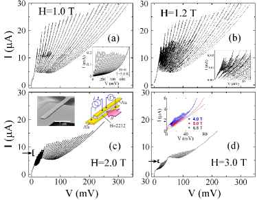
Figure 2 illustrates the close-up details of Fig. 1(a) for 1 T (red and green curves), together with the zero-field IQT curves (gray ones). The red and green curves are bordered around 10 A. In the low-bias red-curve region the 1 T branches are in exact coincidence with the zero-field IQT branches. This implies that JVs are completely pinned down without showing any JV-flow voltages and thereby constitute the static-vortex state Pin . This also implies that the magnetic field very weakly influences the resistive junctions. As one moves to more right branches, junctions containing static JVs (thus, in the zero-voltage state) turn into the IQT state one by one (see the lower schematic JV configurations), causing the voltage jumps between neighboring branches.
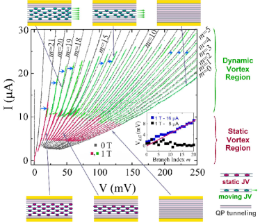
On the other hand, the green-curve region represents the dynamic-vortex state, where the JVs are depinned by a higher bias current and thus each IQT branch is shifted by the corresponding JV-flow voltage as denoted by blue arrows for some branches. The inset of Fig. 2 shows the voltage difference () between a zero-field IQT branch and the corresponding branch in 1 T for each value of at the given bias currents. The branch index denotes the number of junctions containing dynamic vortices. For =8 A in the red-curve region, almost uniformly vanishes, supporting that the JVs in all the junctions are static in this region. For =16 A in 1 T, on the other hand, rises linearly with increasing , satisfying the relation . This indicates that, as more junctions turn into the dynamic-vortex state, all the depinned JVs move with a uniform velocity, which is consistent with the previous studies on the Shapiro step response in the coherent JV-flow state Latyshev et al. (2001). Here, (e.g., 0.44 mV at 16 A) is the average JV-flow voltage contribution of each junction for a given field and a current. Thus, the kink near 10 A in the 1 T I-V curves represents the boundary between the regions of static JVs (showing pure IQT branches) and the dynamic JVs (showing branches of IQT and moving JVs).
In Fig. 2, the static-JV state (red curves) for high values abruptly turns into the corresponding dynamic-JV state (green curves). But, in fact, the fine subbranches near the kink seen in Figs. 1(a) and 2 signify the gradual transition between the two JV states as JVs are depinned separately in each junction. Each subbranch corresponds to different number of junctions containing moving JVs. Subbranches become clearer for a slightly higher magnetic field of 1.2 T as seen in the inset of Fig. 1(b). Here, a higher- branch has more combinatorial configurations of junctions with static and dynamic JVs. That causes a branch located more left to split into a higher number of subbranches as in the inset of Fig. 1(b). With increasing fields these subbranches become separated from IQT branches, developing into the JVFBs in higher magnetic field above 2 T [Figs. 1(c) and (d)]. This feature can be qualitatively understood if one assumes that the main pinning force acting on JVs, in this relatively low in-plane field range, is from any field-independent pinning sourcesPin . Then the total Lorentz force on JVs in a bias current increases for a higher in-plane field as more JVs are introduced to a junction while the pinning force remains insensitive to the in-plane field strength. In consequence, the subbranches move to a lower-bias current region and get separated from the IQT branches when the depinning currents [denoted by the arrows in Fig. 1(c) and (d)] become smaller than the retrapping current of the JJs, at which the junctions in the IQT state turn into the Cooper-pair tunneling state.
Detailed development of the JVFBs is more clearly demonstrated in the presence of pancake vortices (PVs). A PV in a superconducting CuO2 plane, which can be easily pinned down by defects in a crystal such as the oxygen vacancies, tends to exert a pinning force on adjacent JVs by the attractive interaction Koshelev et al. (2006); Bulaevskii et al. (1996). Figures 3(a)–(d) illustrate the variation of the JV-flow I-V curves with slightly tilting the sample stack with respect to the best-aligned in-plane position in 4 T. The JVFBs extend with increasing the c-axis field component along with the slight increase of the tilt angle [=350 Oe for =0.5∘]. The shape of the JVFBs was highly symmetric with respect to =0∘ (not shown). For a higher tilt angle, larger bias currents are required to depin JVs from the increased population of PVs, which extend the JVFBs into a higher bias current region. This PV-pinning effect on the JVFBs was also reproduced as the PVs were generated in a low c-axis-oriented field (an order of a few tens Oe) by a separate Helmholtz coil with the main solenoid at the best-aligned in-plane field position (not shown).
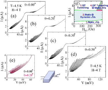
Once a JV is depinned, the PVs exert a far less effect on the JV motion for low tilt angles although the presence of higher-density PVs in a higher tilt angle may slow down the JV motion Koshelev et al. (2006). This bears an analogy with the fact that the dynamic friction coefficient is much smaller than the static one. Thus, JVFBs for two different field angles almost overlap as seen in Fig. 3(e). In this situation, as the depinning current increases for a higher tilt angle, the maximum voltage at the switching current of each JVFB is also enhanced. But, this feature is in contradiction to the picture of the resonance of JVs with the transverse plasma modes Kleiner (1994) as the cause of branching of JV-flow I-V curves. In this picture, the switching voltage between branches corresponds to the resonant propagation mode velocity of the transverse Josephson plasma excitation. For a fixed value of an in-plane field with a constant JV number density, the switching voltage should be insensitive to as the resonant mode velocity, which is proportional to (; Josephson plasma angular frequency) Machida et al. (2000), is independent of the Josephson critical current .
As exceeds 0.4∘ [Fig. 3(d)], the branch structure is modified considerably so that JVFBs become much more pronounced and extend into the “IQT-branch region”, which will be referred to as “extended-JV branches”. As it will be discussed in detail below, this extended-JV branches arise from the combined distribution of junctions with static JVs and the ones in the IQT state.
Figure 4 illustrates JV configurations of Fig. 3(d). The lowest-voltage single branch (for 3 A) represents the state where all the stacked junctions, except for the two surface junctions, retain only static JVs [configuration (i)]. The finite voltage of the branch in this state is generated by the IQT in the two surface junctions. This low-bias single branch, with a static triangular JV configuration, however, showed magnetoresistance oscillations with the periodicity of a half-flux-quantum entry per junction Ooi et al. (2002); Koshelev (2002); Machida (2003), when JVs were put into a thermally depinned dynamic state at a higher temperature range of 50-80 K (not shown). In the JVFB region for 26 A, JVs are represented by the combination of the static and dynamic states [(ii)–(iv)]. The I-V characteristics in the regime are determined by the dissipation due to the dynamic JVs. As one moves to right in the JVFB region the static JVs in different junctions are separately depinned and turn into the dynamic state. Thus, the rightmost branch for 6 A arises from the dynamic JVs in all 21 junctions [(iv)].
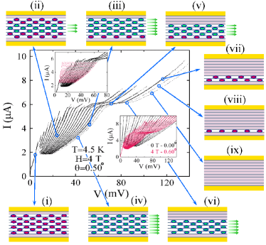
In the bias region of 6 A, junctions with moving JVs progressively turn into the IQT state [(v) and (vi)]. All the junctions retaining moving JVs are resultantly in the IQT state [(vii) to (ix)] in the extended-JV-branch region (7 A). But, the remaining junctions with static JVs, without phase variations, are stable and thus survive even in the high-current region. The static character of JVs deep in the extended-JV-branch region is clearly confirmed by the lower inset of Fig. 4, where the extended JV branches of 4 T at converge to the zero-field IQT branches (black curves). Here, only junctions in the IQT state contribute to the tunneling voltage while the rest of junctions containing static JVs show no dissipation. In the work of Ref. Bae et al. (2007b), no JV-motion-induced THz emission was detected in the extended-JV-branch region of a Bi-2212 stack, which also confirms that only static JVs are present in the region.
Analysis of Fig. 4 renders the summary diagram of Fig. 3(f) for different regimes of JV states in Figs. 3(a)–(d) as a function of the c-axis field component of up to 350 Oe (corresponding to up to 0.5∘). JJs are all in the IQT state for 6 A in 280 Oe (or 0.4∘) [region 3]. But they turn into the extended-JV-branch regime for 6 A in 280 Oe [region 4]. A transitional region exists between the regions 2 and 4, which represents the combined state of static and dynamic JVs, and IQT junctions.
It should be emphasized that, although the IQT branches in Fig. 1(d) look similar to the extended JV branches in Fig. 4, they correspond to totally different JV states. These IQT branches result from the junctions retaining dynamic JVs in combination with IQT junctions, which is essentially same as the state of junctions for the green curves in Fig. 2. Here, the voltage difference between neighboring branches is caused by turning the dynamic JV state (thus, a Josephson pair-tunneling state) into the IQT state in a junction. The extended JV branches, however, correspond to the combined state of static JVs and IQT junctions, where the interbranch voltage difference is due to turning of the static JV state (also a pair-tunneling state) into the IQT state in a junction.
In the presence of the strong inductive coupling between stacked junctions, the static JVs are known to be stabilized in a triangular JV lattice Bulaevskii and Clem (1991); Hu and Tachiki (2004); Nonomura and Hu (2006); Koshelev (2006). The structure of the moving JVs in the dynamic state, however, is still controversial. It is widely accepted that the slowly moving JV lattice is triangular Ooi et al. (2002) and becomes unstable at a JV-flow velocity higher than the critical value, which is is close to the lowest mode velocity of the plasma excitation in stacked JJs Artemenko and Remizov (2003); Pedersen and Sakai (1998); Hechtfischer et al. (1997). However, other possibilities are also suggested. Those include assorted mixture of triangular and rectangular JV lattices formed by the resonance between the plasma excitation modes and collectively moving JVs Kleiner et al. (1994); Machida et al. (2000); Bae et al. (2007a) or a rectangular lattice in a certain range of external magnetic field when the effect of boundary potential is significant Machida (2006); Koshelev (2007). This study, however, indicates that moving JVs form a triangular lattice in the entire JVFBs region ( ).
The upper inset of Fig. 4 shows a set of curves that are obtained from the rightmost JVFB in the main panel of Fig. 4, on the assumption that each junction contributes the same JV-flow voltage for a given bias current. When these curves are overlapped on the JVFBs of the main panel (black curves) an almost perfect scaling of the JVFBs is seen. The equally spaced JVFBs imply that the total JV-flow dissipation per junction, which involves both in-plane and c-axis dissipation Koshelev (2000); Latyshev et al. (2003), is same regardless of the number of junctions with moving JVs. Since the in-plane screening current for a moving JV is time-varying it generates finite dissipation, although it is formed in the superconducting layers. The in-plane dissipation in a moving rectangular JV lattice, however, is almost negligible except in the top and bottom junctions because, in this JV configuration, the screening currents induced in an extremely thin (only 0.3-nm thick) CuO2 layer by two moving JVs in neighboring junctions are cancelled with each other. Thus, the voltage difference between neighboring JVFBs is expected to become larger in a more right branch for more junctions of moving JVs. But, this is not consistent with the observed uniform spacing between JVFBs. Moreover, a rectangular JV lattice of vanishing in-plane dissipation should lead to the rightmost JVFB, which represents the full JV-flow dissipation along the c axis in all the junctions, falling on the zero-field rightmost IQT branch. But this expectation is also in contradiction to the observation [see the lower inset of Fig. 4]. On the other hand, the triangular lattice structure of moving JVs with nonzero (actually maximum) in-plane screening current and dissipation results in the dissipation that is independent of the number of junctions with moving JVs. The finite in-plane dissipation also explains the observed feature that the voltage of the rightmost JVFB falls short of that of the rightmost IQT branch. Thus, our JV-flow data provide an evidence that moving JVs form a triangular lattice Tri in the entire JVFBs region ( ). The formation of triangular JV lattice was previously confirmed by the magnetoresistance oscillation Ooi et al. (2002) for slowly flowing JVs that are thermally depinned from the crystal edge potential at sufficiently high temperatures.
This picture of the triangular dynamic JV lattice, however, is not consistent with the characteristics of the JV-motion-induced THz-emission observed previously Bae et al. (2007b). In the study, the frequency and the power of the emitted wave turned out to be proportional to the total bias voltage () over a stacked oscillator junction and the square of the number of junctions with moving JVs (), respectively, which cannot be explained in terms of the triangular lattice. For a moving triangular JV lattice, a naive consideration leads to the emission frequency corresponding to the voltage per JV-flow junction, (=/). Also, the emitted waves from neighboring two junctions are out of phase, interfering destructively. In this case, the emitted power should be oscillating with rather than monotonically increasing in proportion to . Thus, further examination of the characteristics of JV-motion-induced THz emission is required to clarify the inconsistency concerning the JV lattice structure in the fully dynamic state.
For the static JV state the inductive coupling is weaker than the pinning of JVs, so that depinning of JVs takes place separately in each junction. But the inductive coupling restores its dominant role in the dynamic JV state, for which the pinning strength is reduced, and thereby a coherently moving JV lattice configuration can be established.
III Conclusion
Stacks of Bi-2212 intrinsic Josephson junctions sandwiched between two gold layers are employed to study the Josephson vortex (JV) dynamics excluding the interference of the basal part. Extreme sensitivity of the JV-flow characteristics to the field tilt angle from the in-plane position requires the accurate in-plane field alignment. Careful analysis of JV-flow branches (JVFBs) obtained under different high-field strength and slightly tilted field angles leads to the conclusion that the JVFBs arise from combinatorial combinations of three distinct JV states realized in different junctions and evolving separately with magnetic field and bias current: static Josephson vortex lattice, coherently moving lattice, and incoherent quasiparticle tunneling state. Coherently moving JVs establish a triangular lattice in the entire JVFBs region, as confirmed by the constant voltage difference between JVFBs. The voltage of the rightmost JVFB, which is smaller than that of the maximum zero-field quasiparticle-tunneling branch in a given current, is consistent with the formation of a triangular lattice configuration in the dynamic state. Here, the difference in the voltage is caused by the in-plane dissipation by the JVs in motion. Information on the JV dynamic states and interaction between JVs and PVs can be conveniently utilized to control the JV motion in stacked Josephson junctions.
Acknowledgements.
HJL acknowledges the valuable discussion with M. Machida. We appreciate U. Welp for critical reading and valuable suggestions. This work was supported by Acceleration Research Grant (No. R17-2008-007-01001-0) administered by Korea Science and Engineering Foundation. Work in Argonne was supported by U.S. DoE Office of Science under Contract No. DE-AC02-06CH11357.References
- Kleiner et al. (1992) R. Kleiner, F. Steinmeyer, G. Kunkel, and P. Müller, Phys. Rev. Lett. 68, 2394 (1992).
- Bulaevskii and Clem (1991) L. N. Bulaevskii and J. R. Clem, Phys. Rev. B 44, 10234 (1991).
- Hu and Tachiki (2004) X. Hu and M. Tachiki, Phys. Rev. B 70, 064506 (2004).
- Nonomura and Hu (2006) Y. Nonomura and X. Hu, Phys. Rev. B 74, 024504 (2006).
- Koshelev et al. (2006) A. E. Koshelev, Y. I. Latyshev, and M. Konczykowski, Phys. Rev. B 74, 104509 (2006).
- Koshelev and Aranson (2000) A. E. Koshelev and I. S. Aranson, Phys. Rev. Lett. 85, 3938 (2000).
- Artemenko and Remizov (2003) S. N. Artemenko and S. V. Remizov, Phys. Rev. B 67, 144516 (2003).
- Bae et al. (2007a) M.-H. Bae, J.-H. Choi, and H.-J. Lee, Phys. Rev. B 75, 214502 (2007a).
- Kleiner (1994) R. Kleiner, Phys. Rev. B 50, 6919 (1994).
- Pedersen and Sakai (1998) N. F. Pedersen and S. Sakai, Phys. Rev. B 58, 2820 (1998).
- Machida et al. (2000) M. Machida, T. Koyama, A. Tanaka, and M. Tachiki, Physica C 330, 85 (2000).
- Kim et al. (2005) S. M. Kim, H. B. Wang, T. Hatano, S. Urayama, S. Kawakami, M. Nagao, Y. Takano, T. Yamashita, and K. Lee, Phys. Rev. B 72, 140504 (2005).
- Latyshev et al. (2001) Y. I. Latyshev, M. B. Gaifullin, T. Yamashita, M. Machida, and Y. Matsuda, Phys. Rev. Lett. 87, 24007 (2001).
- Koshelev (2000) A. E. Koshelev, Phys. Rev. B 62, R3616 (2000).
- Latyshev et al. (2003) Y. I. Latyshev, A. E. Koshelev, and L. N. Bulaevskii, Phys. Rev. B 68, 134504 (2003).
- Ooi et al. (2002) S. Ooi, T. Mochiku, and K. Hirata, Phys. Rev. Lett. 89, 247002 (2002).
- Koshelev (2002) A. E. Koshelev, Phys. Rev. B 66, 224514 (2002).
- Machida (2003) M. Machida, Phys. Rev. Lett. 90, 037001 (2003).
- Krasnov et al. (1999) V. M. Krasnov, N. Mros, A. Yurgens, and D. Winkler, Phys. Rev. B 59, 8463 (1999).
- Grigorenko et al. (2001) A. Grigorenko, S. Bending, T. Tamegai, S. Ooi, and M. Henini, Nature 414, 728 (2001).
- Bulaevskii et al. (1992) L. N. Bulaevskii, M. Ledvij, and V. G. Kogan, Phys. Rev. B 46, 366 (1992).
- Koshelev (1999) A. E. Koshelev, Phys. Rev. Lett. 83, 187 (1999).
- Cole et al. (2006) D. Cole, S. Bending, S. Savel’ev, A. Grigorenko, T. Tamegai, and F. Nori, Nature Mater. 5, 305 (2006).
- Tokunaga et al. (2002) M. Tokunaga, M. Kobayashi, Y. Tokunaga, and T. Tamegai, Phys. Rev. B 66, 060507 (2002).
- Vlasko-Vlasov et al. (2002) V. K. Vlasko-Vlasov, A. E. Koshelev, U. Welp, G. W. Crabtree, and K. Kadowaki, Phys. Rev. B 66, 014523 (2002).
- Kim et al. (1999) N. Kim, Y.-J. Doh, H.-S. Chang, and H.-J. Lee, Phys. Rev. B 59, 14639 (1999).
- Wang et al. (2001) H. B. Wang, P. H. Wu, and T. Yamashita, Appl. Phys. Lett. 78, 4010 (2001).
- Bae et al. (2003) M.-H. Bae, H.-J. Lee, and K.-T. Kim, Appl. Phys. Lett. 81, 2187 (2003).
- Allgeier and Schilling (1990) C. Allgeier and J. S. Schilling, Physica C 168, 499 (1990).
- (30) Since natural Josephson junctions in Bi-2212 single crystals have underdamped characteristics each junction presents a quasiparticle tunneling branch in the hysteretic I-V curves.
- Thyssen et al. (1997) N. Thyssen, H. Kohlstedt, and A. V. Ustinov, IEEE Trans. Appl. Supercond. 7, 2901 (1997).
- (32) Inhomogeneous critical current density due to crystal defects or bounday potential of the sample are possible origin of JV pinning.
- Bulaevskii et al. (1996) L. N. Bulaevskii, M. Maley, H. Safar, and D. Domínguez, Phys. Rev. B 53, 6634 (1996).
- Bae et al. (2007b) M.-H. Bae, H.-J. Lee, and J.-H. Choi, Phys. Rev. Lett. 98, 027002 (2007b).
- Koshelev (2006) A. E. Koshelev (2006), arXiv:cond-mat/0602341v1.
- Hechtfischer et al. (1997) G. Hechtfischer, R. Kleiner, K. Schleng, W. Walkenhorst, and P. Müller, Phys. Rev. B 55, 14638 (1997).
- Kleiner et al. (1994) R. Kleiner, P. Müller, H. Kohlstedt, N. F. Pedersen, and S. Sakai, Phys. Rev. B 50, 3942 (1994).
- Machida (2006) M. Machida, Phys. Rev. Lett. 96, 097002 (2006).
- Koshelev (2007) A. E. Koshelev, Phys. Rev. B 75, 214513 (2007).
- (40) Finite in-plane dissipation is also possible for any sheared JV lattice structures. But it has been theoretically predicted that moving JVs are stabilized in a triangular lattice Artemenko and Remizov (2003).