Quantum teleportation of electrons in quantum wires with surface acoustic waves
Abstract
We propose and numerically simulate a semiconductor device based on coupled quantum wires, suitable for deterministic quantum teleportation of electrons trapped in the minima of surface acoustic waves. We exploit a network of interacting semiconductor quantum wires able to provide the universal set of gates for quantum information processing, with the qubit defined by the localization of a single electron in one of two coupled channels. The numerical approach is based on a time-dependent solution of the three-particle Schrödinger equation. First, a maximally entangled pair of electrons is obtained via Coulomb interaction between carriers in different channels. Then, a complete Bell-state measurement involving one electron from this pair and a third electron is performed. Finally, the teleported state is reconstructed by means of local one-qubit operations. The large estimated fidelity explicitely suggests that an efficient teleportation process could be reached in an experimental setup.
pacs:
73.63.Nm, 03.65.Ud, 85.35.BeI Introduction
Quantum teleportation is the process where a quantum state is transferred from one system to another one at a different location. It relies on quantum entanglement, the most peculiar trait of quantum mechanics. In the protocol described by Bennett et al.Bennett et al. (1993) the sender Alice and the receiver Bob share an entangled pair of particles. Alice entangles her particle with a third one, namely the one whose state is to be teleported. Then she performs a destructive joint-measurement on the two-particle system on her side. Next, she communicates through a classic channel the outcome of the measure to Bob. Through this information he can reconstruct the original quantum state by simply applying local operations on his particle. Clearly the scheme of teleportation relies on the prior establishment of quantum entanglement between the two parties. However, only classical communication is used after the particle to be teleported comes into play at Alice side.
While experimental realization of quantum teleportation protocols has been performed in NMR Nielsen et al. (1998), optical Zhao et al. (2004), and atomic systems Olmschenk et al. (2009), no evidence of teleportation in semiconductor systems has been achieved so far. Indeed, semiconductor technology represents a viable approach for the realization of quantum computing devices, and quantum teleportation would be a crucial validation of its potentiality. Theoretical proposals for electron teleportation in solid-state systems are based on single Wang and Kais (2006); Sauret et al. (2003) and double de!Visser and Blaauboer (2006); de Pasquale et al. (2004); Reina and Johnson (2000) quantum dots. Teleportation protocols using edge channels in the quantum Hall effect have also been advanced Beenakker and Kindermann (2004). However, quantum-wire systems have the advantage of intrinsically providing the qubit transmission between specified locations, as required by the DiVincenzo criteria DiVincenzo (2000). Furthermore, they could be directly integrated in traditional electronic circuitry and allow in principle the implementation of a large number of quantum hardware units thus overcoming the scalability problem. In this frame, coherent electron transport in systems of couples of semiconductor quantum wires has been used to design qubits and to propose fundamental one- and two-qubit quantum gates Bertoni et al. (2000); Ionicioiu et al. (2001). Furthermore, the use of surface acoustic waves (SAWs) as a mean to inject and drive carriers along the wires presents some advantages with respect to the free propagation along quasi-1D channels since it prevents the spreading of the electron wavefunction, it reduces undesired reflection effects, and it makes the electron more immune to the decohering effects of the phonons Buscemi et al. (2009); Rodriquez et al. (2005); Barnes et al. (2000).
In this work we propose and simulate numerically a scheme to perform quantum deterministic teleportation of electrons in a device consisting of three couples of semiconductor quantum wires. The carriers are embedded in the minima of SAWs, propagating in the wires direction. The qubit-state is encoded through the localization of a single electron in one of two parallel quantum wires. In our scheme, the Coulomb interaction between carriers is used first for the production of an Einstein-Podolsky-Rosen (EPR) pair of electrons, and then for the rotation of the Bell states needed to perform a Bell measurementBennett et al. (1993); Benenti et al. (2004). We note that the teleportation model described in the following could also be applied, without qualitative modifications, to edge channels in the quantum Hall regime. In fact, the latter system has already successfully exposed the two-particle quantum interference via an electronic version of the Hanbury Brown Twiss setup Samuelsson et al. (2004); Neder et al. (2007).
II The physical system
The physical system used to implement our quantum teleportation scheme consists of three electrons injected by SAW along three couples of GaAs quantum wires. We assume that the device operates at low temperatures (simulations are performed at zero temperature) in order to have a negligible number of electrons in the conduction band and to minimize decoherence effects due to the interactions of electron with lattice vibrations. The use of SAW for the injection and transport of electrons in the quantum wires Barnes et al. (2000) allows a single carrier to be captured into a minimum of the sinusoidal piezoelectric wave propagating along the device and inhibits the natural spatial spreading of the wavepacket. In this way the particle is confined in a moving quantum dot Shilton et al. (1996) and a so-called flying qubit is realized Rodriquez et al. (2005).
In order to implement the quantum operations for the teleportation scheme we employ three elements: an electronic beam splitter , a phase shifter and a Coulomb coupler Barenco et al. (1995).
The former is realized through a coupling window between the two wires of a qubit, able to split an incoming wavefunction into two parts Ramamoorthy et al. (2006). In terms of qubit transformations it corresponds to and . The electronic phase shifter is realized by introducing a suitable potential barrier in the wire (). It acts only on a single qubit state by adding a phase factor, namely and . Similarly, and . The Coulomb coupler is the only two-qubit gate. It consists of a region in which two electrons propagating along two different wires get close enough to each other to give rise to an effective interaction. A phase is added if and only if the two-qubit systems is in and the gate acts as follows: , leaving the other three two-qubit states unchanged. The above quantum gates have been numerically validated elsewhere Bertoni et al. (2002a). In fact, the phases , and depend upon the physical and geometrical parameters of the system, e.g. the window length, the barrier height/length, the electron-electron coupling strength, the SAW velocity. The proposed teleportation scheme (with the exception of qubit 3 preparation) employs only quantum gates with , , and we tuned the device parameters accordingly. For brevity, in the following we will omit the indication of the above phases.
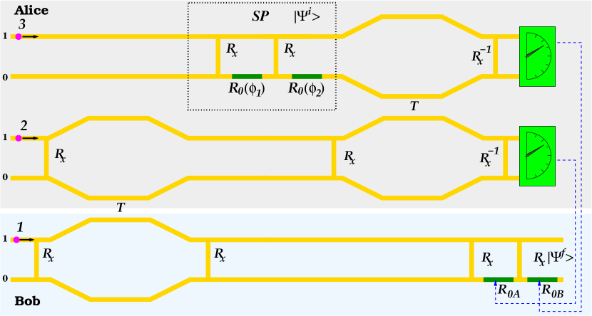
The quantum-wire network for our teleportation protocol is shown in Figure 1. As a first step Alice and Bob must entangle qubits 2 and 1. In particular, they start with an initial state Not (a),corresponding to one electron entering the upper wire of Bob qubit 1 and another electron entering the upper wire of Alice qubit 2. The first block of quantum gates, namely two coupling windows (acting on qubits 1 and 2, respectively) and a Coulomb coupler (acting on qubits 1 and 2, together) produces a maximally entangled state . Now Alice, wants to teleport, the quantum state of electron 3 , obtained from by means of the network of one-qubit gates reported in the State Preparation (SP) box, into electron 1 at Bob side. She performs a so-called Bell measurement on qubits 3 and 2. In fact, as suggested by Brassard et al. Brassard et al. (1998), such a measurement can be realized in two steps: first the Bell states of qubits 2 and 3 are rotated in the basis , then a projective measurement is performed in this latter basis. This approach permits to achieve deterministic quantum teleportation, since it makes possible a full Bell measurement on Alice’s particles. In our scheme, the first step of the Brassard approach is performed by means of the second block of quantum gates involving a Coulomb coupler now acting on the qubits 2 and 3 and three gates (see Fig. 1). The three-qubit state obtained after this block takes the form:
| (1) |
After this rotation Alice can perform two single-particle measurements on qubits 2 and 3. Specifically, such measurements can be realized by means of single-electron transistors, acting as sensitive charge detectors. Once the result is known, it can be transmitted as two classical bits of information to Bob, that can choose the setup of proper unitary operations on his qubit 1 in order to completely recover the initial state . In fact, depending upon the outcome of the measurement on qubits 2 and 3, suitable potential barriers acting as phase shifters are eventually introduced between the two coupling windows, according Table 1.
| qubit 3 | qubit 2 | ||
|---|---|---|---|
| 0 | 0 | YES | YES |
| 0 | 1 | YES | NO |
| 1 | 0 | NO | YES |
| 1 | 1 | NO | NO |
III The numerical approach
The network of gates described in Sec. II has been simulated by solving numerically the time-dependent Schrödinger equation for the three electrons injected in the device. GaAs material parameters have been used. Since a direct solution of the 3D-Schrödinger equation for the whole three-particle wavefunction results too demanding in terms of computational resources, a semi-1D model has been adopted, as described in the following by referring to Fig. 1. The network is defined in the -plane. In the direction the electrons are always supposed to be in the ground state of the quantum well defining the plane of the wires. The direction is explicitely included in the simulations through the variables, defining the position of the three carriers along the wires. Specifically, in the computational approach adopted is discretized with a point-grid of resolution nm. For the direction, the variables can assume only the values 0 or 1, identifying one of the two possible wires of a qubit, that is the qubit state.
This allows us to move from a time dependent Schrödinger equation for a seven-variable wavefunction to eight coupled Schrödinger equations of the form
| (2) |
The potential term appearing in the above equation is given by the sum of two contributions. The first stems from the SAW time-dependent potential and reads
| (3) |
where indicates the amplitude of the potential, its wavelength, and the sound velocity. Specifically, in the numerical investigations performed, = 20 meV, = 200 nm, and cm s The second term represents the screened Coulomb interaction between carriers, computed from the geometry of the system and can be written in the form
| (4) |
where = with indicating the distance between the wires and at the positions and , respectively. This is a Coulomb potential multiplied by an exponential damping term, corresponding to Debye wave vector . In particular, in our calculations the latter has been taken equal to 0.2 nm-1: a value of the same of order of the ones given in the literature Ferry (1991). Due to the geometry of the system and to screening effects, the Coulomb interaction can be considered negligible everywhere for not adjacent qubits, that is qubit 1 and 3, and in the regions not involving the Coulomb coupler for nearby qubits.
Each of the eight coupled Schrödinger equations of Eq. (III) has been solved by means of simple-finite-difference relaxation method applied at each time step of the time evolution performed in a Crank-Nicholson scheme with =0.01 fs Press et al. (1992); Not (b).
It is worth noting that in the simulation of the three-particle wave function dynamics, the only gate that presents a computational challenge due to its spatial extension and the two-particle potential involved, is the Coulomb coupler . However, it is not always necessary to compute its effect on the whole wave function. In fact, when the first gate comes into action by entangling electrons 1 and 2, electron 3 wave function remains factorizable. As a consequence, before the second gate, a two-particle simulation is sufficient.
The numerical estimation of the second gate, between qubit 2 and 3, requires more care since at this stage qubit 1 is already entangled with qubit 2. This entanglement is not only related to the localization of electrons in one of their wires, but also to their positions and . As a consequence, the effect of the second Coulomb coupler must be computed on the whole three-particle wave function. Thanks to the superposition principle and to the fact that the interaction is just among electrons 2 and 3, we performed different two-particle simulations for different values of and then computed the final state as the combination of the different evolutions. We found that, due to the sharp localization of the spatial wavepackets and to the small -direction entanglement, the solution turns out to be practically independent from the choice of , as it will be shown by the numerical results reported in the next section.
A number of numerical simulations have been performed in order to obtain the optimal geometry for the Coulomb coupler . This is reached when the delay phase attains . As shown in other works Bertoni et al. (2002b), the latter mainly depends upon two geometrical parameters: the length of the coupling region and the distance between the coupled wires. From the optimization procedure, we find that the Coulomb coupler is 150 nm long while the coupled wires are 5 nm distant from each other. This geometry allows a value of 0.88 for the delay-phase , which is good enough for realizing both the initial maximally entangled state and the final rotation of the Bell states at Alice side. The experimental realization of the Coulomb coupler is the most challenging part. Specifically, the angle formed by a wire where it bends towards the other qubit must be small enough in order to make reflection phenomena negligible. In addition, no tunnelling between the two wires must be present to let the two wavefunctions only interact through Coulomb coupling.
Obviously, within our semi 1D-model it is not possible to simulate directly the dynamics of the wave function splitting by a coupling window leading to the one-qubit transformation . In fact, we exploited the results of 2D simulations to validate the qubit transformations Bertoni et al. (2000) and include the beam splitters through their corresponding transformation matrix.
IV Results and discussion
We have performed our numerical simulations to teleport many test states prepared by tuning the phase and setting to for the phase shifters in the SP box of Fig. 1.
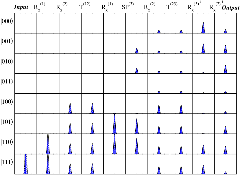
Figure 2 summarizes the three-qubit dynamics estimated numerically for the case of (corresponding to ), starting from the carrier-injection instant up to the single-particle measurements on Alice’s qubits. The square modulus of the eight components of the three-particle wavefunction is reported being the latter evaluated for the three electrons in the same position. We initialized the system in (electrons injected in the upper wire of each couple). The first column of Fig. 2 shows the only non vanishing component of the wavefunction. The two gates located in the left part of the device split in the same way the electrons of qubits 1 and 2 (third column of Fig. 2). Then, the Coulomb coupler acting between qubits 1 and 2 induces a phase of 0.88 in with respect to the other components. When the injected carriers reach the second coupling window between the wires of qubit 1, the new rotation leads with good approximation to the three-qubit state , as shown in the fifth column. This corresponds to an EPR pair of electrons 1 and 2. However, we find that the component is small but not zero. This can be ascribed to the fact that the rotation performed by the simulated gate is not exactly . Then the single-qubit gates of the SP block operate onto and the state is produced.
From this stage, single and two-qubit operations act only onto electrons 2 and 3, in order to perform the complete rotation of the Bell state of qubits 2 and 3 into separable states. The components of the three-particle wavefunction displayed in the last column of Fig. 2 show the state on which the destructive measurements will be performed by Alice. The state components depend on the coefficients of the spectral decomposition of the teleported state in terms of the single qubit-states and . In agreement with the theoretical prediction, we find that, for , the square modulus of the components , , , and has the same form and value, which approximately is the triple of the one found for ,, , and , respectively. Such a result shows the good efficiency reachable in the proposed teleportation scheme.
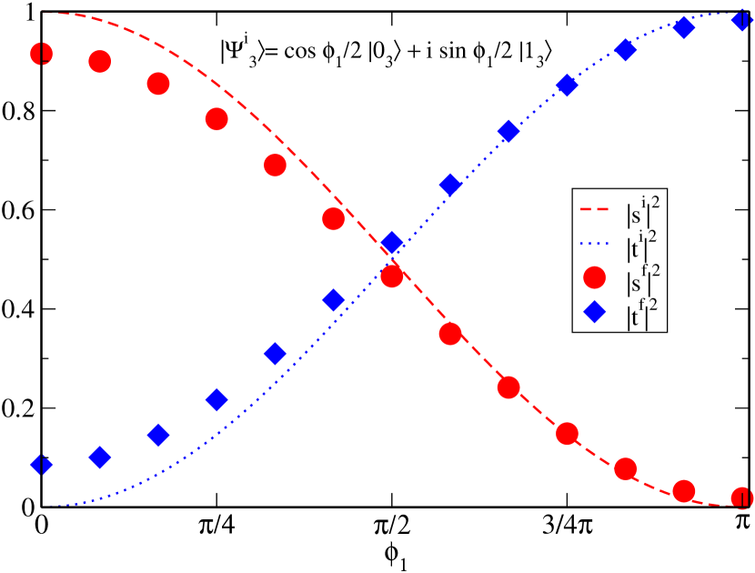
To better quantify the reliability of the teleportation, we also compare the square modulus of the coefficients and of the initial state with the coefficients and of the final state obtained by Bob after the teleportation (see Fig. 3). The fidelity of the teleportation process, given by , is strictly related to the ratio : the closer to 1 the latter is, the larger values the fidelity attains. For the set of teleported states, obtained by varying the phase from 0 to , the above ratio ranges from to 1.02 and, for , it is almost equal to 1 . This implies that the state is teleported with the maximum efficiency. This proves an important point: the fidelity of the proposed teleportation scheme remains very high also for non ideal entangling gates and this can certainly be considered a plus in view of an experimental implementation.
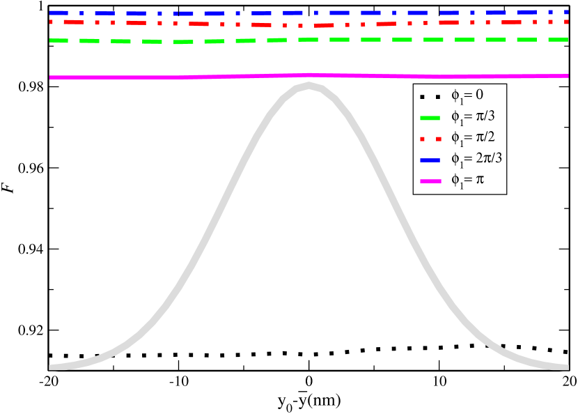
In order to test the validity of the approach used in the numerical solution of the 3D-Schrödinger equation for three-particle wavefunction, we have reported in Fig. 4, the fidelity as a function of (that is the point along the wires of qubit 3 where the carrier is assumed to be found in a measurement process). This is repeated for five teleported states corresponding to different values of the phase with set to . We find that is essentially constant. This implies that the efficiency of our quantum teleportation scheme does not basically depend upon the position variable along the wire direction of the three particles. This behavior, due to the confinement of the carriers in the SAW minima leading to a sharp localization of the corresponding wavepackets, proves the validity of the two-particle approach adopted.
Finally, the effect of the temperature deserves a few comments. As stated in Sec. II, numerical simulations of charge transport through quantum wires has been performed at zero temperature, that is fully coherent propagation of electrons has been assumed. Such an approximation allows one to neglect the effects due to the piezoelectric coupling between charge carriers and acoustic phonon modes. In fact, the latter represents the main decoherence source of our physical system. Experimental investigations about both SAW assisted charge transport Naber et al. (2006) and low-dimensional devices suitable for quantum computing Ji et al. (2003) are usually carried out at temperatures in the range of mK. A realization of our device would require such low temperatures at which the stimulated absorption and emission processes of acoustic phonons are weak enough to be neglected. In fact, the mean occupation number of acoustic phonons with momentum energy 5 meV (of the order of the energy difference between the ground and the first excited bound state of the electrons) can be evaluated from Bose-Einstein statistics and results to be practically zero at a temperature of 100 mK. Thus it seems reasonable to take into account only spontaneous emission processes. These obviously affect the ideal fidelity of the gates implemented in the teleportation scheme. However such unavoidable effects can be minimized by inserting suitable quantum error correction codes in our scheme Shor (1995); Steane (1996). This corresponds to use more two-qubit gates for the same computation. Moreover, we expect that in an experimental setup the quantum teleportation process, would be repeated many times. In fact, the simulations performed in this work represent a “single shot” of the network in Fig. 1, with three electrons in the same minimum of the SAW. However, it is reasonable to think that in the experiment electrons also populate the other minima, as described in Ref. Barnes et al., 2000. This corresponds to a multiple repetition of the teleportation scheme (one each SAW minimum).
V Conclusions
Here we have proposed a device for the deterministic teleportation of electrons injected and driven by SAWs in a network of coupled quantum wires. It consists of a sequence of single-qubit (beam splitter and phase shifter) and two-qubit (Coulomb Coupler) gates which allows a high level of control over the state evolution. Numerical simulations show that, with a suitable design of the nanostructure, the fidelity of the teleportation can reach values close to 1, indicating a high-realibility of the process. Furthermore, we also mention the possibility of using carrier transport in edge states for quantum Hall effect regime, instead of SAW-assisted electron transport in quantum wires.
The experimental realization of the device proposed is challenging since it requires the use of frontier mesoscopic semiconductor technology. However, both the new developments in nanostructures fabrication permitting the control of the coupling between two modes of two 1D-channels Renner and Fischer (1995); Fischer et al. (2006), and the recent observation of single electron dynamics in experiments of SAW assisted charge transport Kataoka et al. (2009), seem to indicate the feasibility of an experimental setup of our device. Its realization would undoubtedly represent a great step forward toward quantum-computing capable architectures scalable and integrable with traditional microelectronics.
Acknowledgements.
We are pleased to thank Carlo Jacoboni for fruitful discussions. We acknowledge support from CNR Progetto Supercalcolo 2008 CINECA.References
- Bennett et al. (1993) C. H. Bennett, G. Brassard, C. Crépeau, R. Jozsa, A. Peres, and W. K. Wootters, Phys. Rev. Lett. 70, 1895 (1993).
- Nielsen et al. (1998) M. A. Nielsen, E. Knill, and R. Laflamme, Nature 396, 52 (1998).
- Zhao et al. (2004) Z. Zhao, Y.-A. Chen, A.-N. Zhang, T. Y. H. J. Briegel, and J.-W. Pan, Nature 430, 54 (2004).
- Olmschenk et al. (2009) S. Olmschenk, D. N. Matsukevich, P. Maunz, D. Hayes, L.-M. Duan, and C. Monroe, Science 323, 486 (2009).
- Wang and Kais (2006) H. Wang and S. Kais, Chemical Physics Letters 421, 338 (2006).
- Sauret et al. (2003) O. Sauret, D. Feinberg, and T. Martin, Eur. Phys. J. B 32, 545 (2003).
- de!Visser and Blaauboer (2006) R. L. de Visser and M. Blaauboer, Phys. Rev. Lett. 96, 246801 (2006).
- de Pasquale et al. (2004) F. de Pasquale, G. Giorgi, and S. Paganelli, Phys. Rev. Lett. 93, 120502 (2004).
- Reina and Johnson (2000) J. A. Reina and N. F. Johnson, Phys. Rev. A 63, 012303 (2000).
- Beenakker and Kindermann (2004) C. W. J. Beenakker and M. Kindermann, Phys. Rev. Lett. 92, 056801 (2004).
- DiVincenzo (2000) D. P. DiVincenzo, Fortschritte der Physik 40, 771 (2000).
- Bertoni et al. (2000) A. Bertoni, P. Bordone, R. Brunetti, C. Jacoboni, and S. Reggiani, Phys. Rev. Lett. 84, 5912 (2000).
- Ionicioiu et al. (2001) R. Ionicioiu, G. Amaratunga, and F. Udrea, International Journal of Modern Physics B 15, 125 (2001).
- Buscemi et al. (2009) F. Buscemi, P. Bordone, and A. Bertoni, Journal of Physics: Condensed Matter 21, 305303 (2009).
- Rodriquez et al. (2005) R. Rodriquez, D. K. L. Oi, M. Kataoka, C. H. W. Barnes, T. Ohshima, and A. K. Ekert, Phys. Rev. B 72, 085329 (2005).
- Barnes et al. (2000) C. H. W. Barnes, J. M. Shilton, and A. M. Robinson, Phys. Rev. B 62, 8410 (2000).
- Benenti et al. (2004) G. Benenti, G. Casati, and G. Strini, Principles of Quantum Computation and Information (World Scientific Publishing, Singapore, 2004).
- Samuelsson et al. (2004) P. Samuelsson, E. V. Sukhorukov, and M. Büttiker, Phys. Rev. Lett. 92, 026805 (2004).
- Neder et al. (2007) I. Neder, N. Ofek, Y. Chung, M. Heiblum, D. Mahalu1, and V. Umansky, Nature 448, 333 (2007).
- Shilton et al. (1996) J. M. Shilton, V. I. Talyanskii, M. Pepper, D. A. Ritchie, J. E. F. Frost, C. J. B. Ford, C. G. Smith, and G. A. C. Jones, Journal of Physics: Condensed Matter 8, L531 (1996).
- Barenco et al. (1995) A. Barenco, C. H. Bennett, R. Cleve, D. P. DiVincenzo, N. Margolus, P. Shor, T. Sleator, J. A. Smolin, and H. Weinfurter, Phys. Rev. A 52, 3457 (1995).
- Ramamoorthy et al. (2006) A. Ramamoorthy, J. P. Bird, and J. L. Reno, Applied Physics Letters 89, 013118 (2006).
- Bertoni et al. (2002a) A. Bertoni, P. Bordone, R. Brunetti, C. Jacoboni, and S. Reggiani, J. Mod. Optics 49, 1219 (2002a).
- Not (a) The subscripts of the qubit states indicate which of the three qubits we are referring to.
- Brassard et al. (1998) G. Brassard, S. L. Braunstein, and R. Cleve, Physica D: Nonlinear Phenomena 120, 43 (1998).
- Ferry (1991) D. K. Ferry, Semiconductors (Macmillan Publishing Company, New York, 1991).
- Press et al. (1992) W. G. Press, S. A. Teukolsky, W. T. Vetterling, and B. P. Flannery, Numerical Recipes in FORTRAN (Cambridge University Press, Cambridge, 1992).
- Not (b) The simulation code used in this work is adapted from TDStool software www.s3.infm.it/tdstool, by one of the authors (A.B.).
- Bertoni et al. (2002b) A. Bertoni, R. Ionicioiu, P. Zanardi, F. Rossi, and C. Jacoboni, Physica B: Condensed Matter 314, 10 (2002b).
- Naber et al. (2006) W. J. M. Naber, T. Fujisawa, H. W. Liu, and W. G. van der Wiel, Physical Review Letters 96, 136807 (2006).
- Ji et al. (2003) Y. Ji, W.Chung, D. Sprinzak, M. Heiblum, D. Mahalu, and H. Shtrikman, Nature 422, 415 (2003).
- Shor (1995) P. W. Shor, Phys. Rev. A 52, R2493 (1995).
- Steane (1996) A. Steane, Proceedings of the Royal Society of London. Series A: Mathematical, Physical and Engineering Sciences 452, 2551 (1996).
- Renner and Fischer (1995) C. Renner and O. Fischer, Phys. Rev. B 51, 9208 (1995).
- Fischer et al. (2006) S. F. Fischer, G. Apetrii, U. Kunze, D. Schuh, and G. Abstreiter, Nat Phys 2, 1745 (2006).
- Kataoka et al. (2009) M. Kataoka, et al., Phys. Rev. Lett. 102, 156801 (2009).