∎
Den Dolech 2, 5600MB Eindhoven, The Netherlands
Institute for Computational Physics, University of Stuttgart, Pfaffenwaldring 27, 70569 Stuttgart, Germany
22email: j.harting@tue.nl 33institutetext: Christian Kunert44institutetext: Institute for Computational Physics, University of Stuttgart, Pfaffenwaldring 27, 70569 Stuttgart, Germany
44email: kuni@icp.uni-stuttgart.de 55institutetext: Jari Hyväluoma66institutetext: Department of Physics, University of Jyväskylä, FI-40014 Jyväskylä, Finland
66email: jari.hyvaluoma@jyu.fi
Lattice Boltzmann simulations in microfluidics: probing the no-slip boundary condition in hydrophobic, rough, and surface nanobubble laden microchannels
Abstract
In this contribution we review recent efforts on investigations of the effect of (apparent) boundary slip by utilizing lattice Boltzmann simulations. We demonstrate the applicability of the method to treat fundamental questions in microfluidics by investigating fluid flow in hydrophobic and rough microchannels as well as over surfaces covered by nano- or microscale gas bubbles.
Keywords:
Apparent and intrinsic slip rough and hydrophobic surfaces lattice Boltzmann simulations1 Introduction
During the last few decades the miniaturization of technical devices down to submicrometric sizes has made considerable progress. In particular, so-called microelectro-mechianical systems (MEMS) became available for chemical, biological and technical applications leading to the rise of “microfluidics” about 20 years ago bib:tabeling-book . A wide variety of microfluidic systems including gas chromatography systems, electrophoretic separation systems, micromixers, DNA amplifiers, and chemical reactors were developed. Next to those “practical applications”, microfluidics was used to answer fundamental questions in physics including the behavior of single molecules or particles in fluid flow or the validity of the no-slip boundary condition bib:tabeling-book ; bib:lauga-brenner-stone-05 . The latter is the focus of the current review and is investigated in detail by mesoscopic computer simulations.
Reynolds numbers in microfluidic systems are usually small, i.e., usually below 0.1. In addition, due to the small scales of the channels, the surface to volume ratio is high causing surface effects like wettability or surface charges to be more important than in macroscopic systems. Also, the mean free path of a fluid molecule might be of the same order as the characteristic length scale of the system. For gas flows, this effect can be characterized by the so-called Knudsen number knudsen09a . While the Knudsen number provides a good estimate for when to expect rarefaction effects in gas flows, for liquids one would naively assume that its velocity close to a surface always corresponds to the actual velocity of the surface itself. This assumption is called the no-slip boundary condition and can be counted as one of the generally accepted fundamental concepts of fluid mechanics. However, this concept was not always well accepted. Some centuries ago there were long debates about the velocity of a Newtonian liquid close to a surface and the acceptance of the no-slip boundary condition was mostly due to the fact that no experimental violations could be found, i.e., a so-called boundary slip could not be detected.
In recent years, it became possible to perform very well controlled experiments that have shown a violation of the no-slip boundary condition in sub-micron sized geometries. Since then, mostly experimental bib:lauga-brenner-stone-05 ; craig-neto-01 ; bib:tretheway-meinhart-04 ; cheng-giordano-02 ; choi-westin-breuer-03 ; baudry-charlaix-01 ; bib:cottin-bizone-etall-02 ; vinogradova-yakubov-03 ; bib:tretheway-meinhart-04 , but also theoretical works vinogradova-95 ; bib:degennes-02 , as well as computer simulations succi02 ; bib:barrat-bocquet-99 ; bib:cieplak-koplik-banavar-01 ; bib:thompson-troian-1997 ; bib:tretheway-zhu-petzold-meinhart-2002 have been performed to improve our understanding of boundary slip. The topic is of fundamental interest because it has practical consequences in the physical and engineering sciences as well as for medical and industrial applications. Interestingly, also for gas flows, often a slip length much larger than expected from classical theory can be observed. Extensive reviews of the slip phenomenon have recently been published by Lauga et al. bib:lauga-brenner-stone-05 , Neto et al. neto-etal-05 , as well as Bocquet and Barrat bib:bocquet-barrat-2007 .
The reason for such findings is that the behavior of a fluid close to a solid interface is very complex and involves the interplay of many physical and chemical properties. These include the wettability of the solid, the shear rate or flow velocity, the bulk pressure, the surface charge, the surface roughness, as well as impurities and dissolved gas. Since all those quantities have to be determined very precisely, it is not surprising that our understanding of the phenomenon is still very unsatisfactory. Due to the large number of different parameters, a significant dispersion of the results can be observed for almost similar systems bib:lauga-brenner-stone-05 ; neto-etal-05 . For example, observed slip lengths vary between a few nanometres bib:churaev-sobolev-somov-84 and micrometers bib:tretheway-meinhart-04 and while some authors find a dependence of the slip on the flow velocity choi-westin-breuer-03 ; bib:zhu-granick-01 ; craig-neto-01 , others do not cheng-giordano-02 ; bib:tretheway-meinhart-04 .
A boundary slip is typically quantified by the so-called slip length – a concept that was already proposed by Navier in 1823. He introduced a boundary condition where the fluid velocity at a surface is proportional to the shear rate at the surface bib:Navier (at ), i.e.,
| (1) |
In other words, the slip length can be defined as the distance from the surface where the relative flow velocity vanishes. Assuming a typical Poiseuille setup consisting of a pressure driven flow of an incompressible liquid between two infinite planes, the velocity in flow direction () at position between the planes is given by
| (2) |
where is the distance between the planes, and the dynamic viscosity. is the pressure gradient. In contrast to a no-slip formulation, the last term in Eq. 2 linearly depends on the slip length .
Most recent computer simulations apply molecular dynamics and report increasing slip with decreasing liquid density bib:koplik-banavar-willemsen-89 ; bib:thompson-robbins-1990 or liquid-solid interactions bib:cieplak-koplik-banavar-01 ; bib:nagayama-cheng-2004 , while slip decreases with increasing pressure bib:barrat-bocquet-99 . These simulations are usually limited to a few tens of thousands of particles, length scales of a few nanometres and time scales of nanoseconds. Also, shear rates are usually some orders of magnitude higher than in any experiment bib:lauga-brenner-stone-05 . Due to the small accessible time and length scales of molecular dynamics simulations, mesoscopic simulation methods such as the lattice Boltzmann method are well applicable for the simulation of microfluidic experiments.
The experimental investigation of apparent slip can be based on different setups: either a fluid is pumped through a microchannel and the measured mass flow rate at the end of the channel is compared to the theoretical value with no slip boundary conditions. From the deviation of the two values, the magnitude of slip can be computed tretheway-meinhart-02 . Another possibility is to measure the slip length directly using optical methods like particle image velocimetry (PIV). Very popular is the modification of an atomic force microscope (AFM) by adding a silicon sphere to the tip of the cantilever. While moving the sphere towards the boundary, the required force is measured. It is possible to measure the amount of slip at the wall by comparing the force needed to move the sphere with its theoretical value vinogradova-yakubov-03 ; bib:vinogradova-96 .
During the last few years, the substantial scientific research invested in the slip phenomenon has lead to a more clear picture which can be summarized as follows: one can argue that many surprising results published were only due to artefacts or misinterpretation of experiments. In general, there seems to be an agreement within the community that slip lengths larger than a few nanometers can usually be referred to as “apparent slip” and are often caused by experimental artefacts. Small slip lengths are experimentally even harder to determine and require sophisticated setups such as the modified atomic force microscopes as described above. Here, small variations of the apparatus such as choosing a different shape of the cantilever or modifying the control circuit of the sample holder can lead to substantial variation of the measurements. Also, the theoretical equations correlating the measured force to the slip length are only valid for perfect surfaces and infinitely slow oscillations of the sphere. Therefore, it is of importance to perform computer simulations which have the advantage that most parameters can be changed independently without modifying anything else. Thus, the influence of every single modification can be studied in order to present estimates of expected slip lengths.
2 Apparent slip in hydrophobic microchannels
The simulation method used to study microfluidic devices has to be chosen carefully. While Navier-Stokes solvers are able to cover most problems in fluid dynamics, they lack the possibility to include the influence of molecular interactions as needed to model boundary slip. Molecular dynamics simulations (MD) are the best choice to simulate the fluid-wall interaction, but the computer power today is not sufficient to simulate length and time scales necessary to achieve orders of magnitude which are relevant for experiments. However, boundary slip with a slip length of the order of many molecular diameters has been studied with molecular dynamics simulations by various authors bib:thompson-troian-1997 ; bib:cieplak-koplik-banavar-01 ; bib:cottin-bizone-etall-04 ; baudry-charlaix-01 ; bib:priezjev-darhuber-troian-2005 .
The current contribution focuses on numerical investigations of the slip phenomenon by means of lattice Boltzmann simulations. While an emphasis is put on reviewing our own contributions to the field, the achievements of other groups are commonly referred to. However, it should be noticed that while a large number of groups utilizes the lattice Boltzmann technique to investigate microfluidic problems, only a very small number of researchers is actually applying the method to studying slippage. Even though interactions have to be described on a mesoscopic scale, this is surprising since mesoscopic simulation methods offer a closer relation to experimentally relevant time and length scales than microscopic techniques such as molecular dynamics.
In the lattice Boltzmann method, one discretizes the Boltzmann kinetic equation
| (3) |
on a lattice. The Boltzmann kinetic equation describes the evolution of the single particle probability density , where is the position, the velocity, and the time. The derivatives represent simple propagation of a single particle in real and velocity space whereas the collision operator takes into account molecular collisions in which a particle changes its momentum due to a collision with another particle. To represent the correct physics, the collision operator should conserve mass and momentum, and should be Galilei invariant. By performing a Chapman Enskog procedure, it can be shown that such a collision operator reproduces the Navier-Stokes equation bib:succi-01 . In the lattice Boltzmann method the time , the position , and the velocity are discretized.
A few groups have applied the lattice Boltzmann method for the simulation of microflows and to study boundary slip. A popular approach is to introduce slip by generalizing the no-slip bounce back boundary conditions in order to allow specular reflections with a given probability succi02 ; bib:tretheway-zhu-petzold-meinhart-2002 ; bib:tang-tao-he-2005 ; bib:sbragaglia-succi-2005 , or to apply diffuse scattering bib:ansumaili-karlin-2002 ; bib:sofonea-sekerka-2005 ; bib:niu-shu-chew-2004 . It has been shown by Guo et al. that these approaches are virtually equivalent bib:guo-shi-zhao-zheng-2007 . Another possibility is to modify the fluid’s viscosity, i.e., the fluid viscosity is modified due to local density variations in order to model slip bib:nie-doolen-chen . In both cases, the parameters determining the properties at the boundaries are “artificial” parameters and they do not have any obvious physical meaning. Therefore, they are not easily mappable to experimentally available values. We model the interaction between hydrophobic channel walls and the fluid by means of a multi-phase lattice Boltzmann model. Our approach overcomes this problem by applying a mesoscopic force between the walls and the fluid. A similar approach is used by Zhu et al. bib:zhu-tretheway-petzold-meinhart-2005 , Benzi et al. bib:benzi-etal-06 , and Zhang et al. bib:zhang-kwok-04 . This force applied at the boundary can be linked to the contact angle which is commonly used by experimentalists to quantitatively describe the wettability of a material benzi-etal-06b ; bib:huang-thorne-schaap-sukop-2007 .
The simulation method and our implementation of boundary conditions are described as follows. A multiphase lattice Boltzmann system can be represented by a set of equations
| (4) |
where is the single-particle distribution function, indicating the amount of species with velocity , at site on a D-dimensional lattice of coordination number (D3Q19 in our implementation), at time-step . This is a discretized version of equation (3) without external forces for a number of species . For the collision operator we choose the Bhatnagar-Gross-Krook (BGK) form bib:bgk
| (5) |
where is the mean collision time for component and determines the kinematic viscosity
| (6) |
of the fluid. The relaxation time is kept constant at in this study. The system relaxes to an equilibrium distribution which can be derived imposing restrictions on the microscopic processes, such as explicit mass and momentum conservation for each species. In our implementation we choose for the equilibrium distribution function
| (7) |
which is a polynomial expansion of the Maxwell distribution. are the velocity vectors pointing to neighbouring lattice sites and are the lattice weights resulting from the velocity space discretization. is the speed of sound for the D3Q19 lattice. The macroscopic values can be derived from the single-particle distribution function , i.e., the density of the species at lattice site is the sum over the distribution functions for all lattice velocities ,
| (8) |
is the macroscopic velocity of the fluid, defined as
| (9) |
Interactions between different fluid species are introduced following Shan and Chen as a mean field body force between nearest neighbors bib:shan-chen-93 ; bib:shan-chen-liq-gas ,
| (10) |
where is the so-called effective mass with being a reference density that is set to in our case bib:shan-chen-93 . is a force coupling constant, whose magnitude controls the strength of the interaction between component and . The dynamical effect of the force is realized in the BGK collision operator (5) by adding an increment to the velocity in the equilibrium distribution function (7). A repulsive potential between surface and fluid can be used to model hydrophobic fluid-surface interactions. Such a potential is realized by attaching the imaginary fluid “density” to the first lattice site inside the wall. Only the distribution corresponding to the rest velocity is filled, while the remaining ones are kept at 0. As a result the only difference between and any other fluid packages on the lattice is that the fluid corresponding to is only taken into account for in the collision step and for the calculation of Eq. 10, but not in the propagation step. Therefore, we can adopt and the coupling constant in order to tune the fluid-wall interaction. is kept at throughout this paper if not mentioned otherwise and all values are reported in lattice units. These parameters allow to simulate a wide range of effective interactions without compromising on numerical stability. Additionally, we apply second order correct mid-grid bounce back boundary conditions between the fluid and the surface which assures vanishing velocities at solid surfaces. Here, a distribution function that would be advected into a solid node is simply reversed and advected into the opposite direction bib:succi-01 .
From molecular dynamics simulations it is known that the fluid-wall interactions causing a slip phenomenon usually take place within a few molecular layers of the liquid along the boundary surface bib:thompson-troian-1997 ; bib:cieplak-koplik-banavar-01 ; bib:cottin-bizone-etall-04 ; baudry-charlaix-01 . Our coarse-grained fluid wall interaction acts on the length scale of one lattice constant and does not take the molecular details into account. Therefore, coarse-grained implementations based on the lattice Boltzmann method are only able to reproduce an averaged effect of the interaction and cannot fully resolve the correct flow profile very close to the wall and below the resolution of a single lattice spacing. However, in order to understand the influence of the hydrophobicity on experimentally observed apparent slip, it is fully sufficient to investigate the flow behavior on more macroscopic scales as they are accessible for experimental investigation. Coarse-grained interaction models could be improved by a direct mapping of data obtained from MD simulations to the coupling constant allowing a direct comparison of the influence of liquid-wall interactions on the detected slip bib:jens-kunert-herrmann:2005 . Similar approaches are known from quantitative comparisons of lattice Boltzmann and molecular dynamics simulations in the literature bib:horbach-suci-2006 ; bib:chibbaro-etal-2008 .
The simulations in this work use a setup of two infinite planes separated by the distance . We call the direction between the two planes and if not stated otherwise is set to lattice sites. In direction we apply periodic boundary conditions. Here, lattice sites are sufficient to avoid finite size effects since there is no propagation in this direction. is the direction of the flow with our channels being lattice sites long. At the beginning of the simulation () the fluid is at rest. We then apply a pressure gradient in the - direction to generate a planar Poiseuille flow. Assuming Navier’s boundary condition, the slip length is measured by fitting the theoretical velocity profile as given by equation 2 in flow direction () at position , to the simulated data via the slip length . We validate this approach by comparing the measured mass flow rate to the theoretical mass flow without boundary slip and find a very good agreement. The dynamic viscosity as well as the pressure gradient needed to fit equation (2) are obtained from our simulation data.
In bib:jens-kunert-herrmann:2005 , we show that this model creates a larger slip with stronger interaction, namely larger and larger . The maximum available slip length measured is in lattice units. For stronger repulsive potentials, the density gradient at the fluid-wall interface becomes too large, causing the simulation to become unstable. At lower interactions the method is very stable and the slip length is independent of the distance between the two plates and therefore independent of the resolution. We also show that the slip decreases with increasing pressure since the relative strength of the repulsive potential compared to the bulk pressure is weaker at high pressure. Therefore, the pressure reduction near the wall is less in the high pressure case than in the low pressure one. Furthermore, we demonstrate that can be fitted with a semi analytical model based on a two viscosity model.
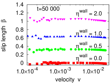
We study the dependence of the slip length on the flow velocity for a wide range of velocities of more than three decades as it can be seen in Fig. 1 and in bib:jens-kunert-herrmann:2005 . In the figure, we show data for different fluid-wall interactions and flow velocities from . For simplicity we restrict ourselves to which is a suitable value found from parameter studies given in bib:jens-kunert-herrmann:2005 . Within this region we confirm the findings of many steady state experiments cheng-giordano-02 , i.e., that the slip length is independent of the flow velocity and only depends on the wettability of the channel walls. Some dynamic experiments, however, find a shear rate dependent slip neto-craig-williams-03 ; bib:zhu-granick-01 . These experiments often utilize a modified AFM as described in the introduction to detect boundary slippage. Since the slip length is found to be constant in our simulations after sufficiently long simulation times, we cannot confirm these results. However, it has been proposed by various authors that this velocity dependence is due to non-controlled effects such as impurities or surface nanobubbles. In simulations we can only find a shear rate dependence if the system has not yet reached the steady state or if time-dependent accelerations are present bib:jens-kunert:2008b .
Our mesoscopic approach is able to reach the small flow velocities of known experiments and reproduces results from experiments and other computer simulations, namely an increase of the slip with increasing liquid-solid interactions, the slip being independent of the flow velocity, and a decreasing slip with increasing bulk pressure. In addition, within our model we develop a semi-analytic approximation of the dependence of the slip on the bulk pressure as described in bib:jens-kunert-herrmann:2005 .
3 Roughness induced apparent slip
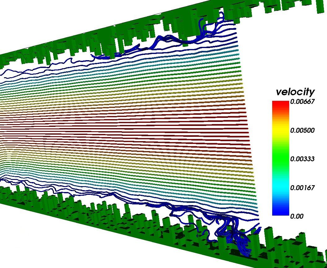
If typical length scales of the experimental system are comparable to the scale of surface roughness, the effect of roughness cannot be neglected anymore. Figure 2(left) shows a typical example of a simulation setup: Poiseuille flow between two rough surfaces. The surface is generated using a random number generator to randomly choose the height of the obstacles at every discrete surface position. As can be observed in the figure, the stream lines of the flow are getting disturbed or trapped between the obstacles at the surfaces. In this section we show that an apparent boundary slip can have its origin in the misleading assumption of perfectly smooth boundaries.
The influence of surface variations on the slip length has been investigated by numerous authors. It was demonstrated by Richardson that roughness leads to higher drag forces and thus to no-slip on macroscopic scales. He has shown that if on a rough surface even a full-slip boundary condition is applied, one obtains a flow speed reduction near the boundary resulting in a macroscopic no-slip boundary condition bib:richardson-73 . An experimental confirmation was later presented by McHale and Newton mchale-newton-04 . Molecular dynamics (MD) simulations of Couette flow between sinusoidal walls have been presented by Jabbarzadeh et al. jabbarzadeh-etal-00 . They found that slip appears for roughness amplitudes smaller than the molecular length scale jabbarzadeh-etal-00 . Sbragaglia et al. applied the LB method to simulate fluids in the vicinity of microstructured hydrophobic surfaces bib:sbragaglia-etal-06 , Al-Zoubi et al. demonstrated that the LB method is well applicable to reproduce known flow patterns in sinusoidal channels bib:alzoubi-brenner-2008 , and Varnik et al. varnik-raabe-06 ; varnik-dorner-raabe-06 have shown that even in small geometries rough channel surfaces can cause flow to become turbulent.
Recently, we presented the idea of an effective wall for rough channel surfaces bib:jens-kunert:2007b . Here, we investigate the influence of different types of roughness on the position of the effective boundary. Further, we show how the effective boundary depends on the distribution of the roughness elements and how roughness and hydrophobicity interact with each other bib:jens-kunert:2008c . Lecoq and coworkers lecoq-etal-04 performed experiments with well defined roughness, and developed a theory to predict the position of the effective boundary. In the experiments they utilised a laser interferometer to measure the trajectory of a colloidal sphere, and thereby determined the lubrication force and an effective boundary position. The used geometry consists of grooves with a triangular profile. For a theoretical description the boundary is expressed in a Fourier series that gives the boundary condition for the Laplace equation. From this an effective boundary can be derived by a fast converting series.
In this paper, we revise our previous achievements and compare them with the theoretical and experimental results of Lecoq and coworkers lecoq-etal-04 .
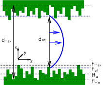
Again, Poiseuille flow measurements are utilized to investigate the effect of interest. The rough surfaces are characterised by the highest point of one plane (), the position of the deepest valley () and the arithmetic average of all surface heights giving the average roughness . In the case of symmetrical distributions we get .
The position of the effective boundary can be found by fitting the parabolic flow profile via the distance . With set to 0 we obtain the no-slip case. To obtain an average value for the effective distance between the planes , a sufficient number of individual profiles at different positions are taken into account. The so found gives the position of the effective boundary and the effective height of the rough surface is then defined by (see Fig. 2, left).
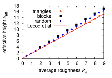
We show that the position of the effective boundary height is depending on the shape of the roughness elements, i.e., for strong surface distortions it is between and times the average height of the roughness bib:jens-kunert:2007b . In Fig 3 we plot the effective boundary positions of different geometries, i.e. randomly distributed grooves with a square profile and grooves with a triangular profile. The results for the triangular ones match with the theoretical value of Lecoq et al. lecoq-etal-04 for a similar geometry.
By adding an additional distance between roughness elements, decreases slowly, so that the maximum height is still the leading parameter. We are also able to simulate flow over surfaces generated from AFM data of gold coated glass used in microflow experiments by O.I. Vinogradova and G.E. Yakubov vinogradova-yakubov-06 . We find that the height distribution of such a surface is Gaussian and that a randomly arranged surface with a similar distribution gives the same result for the position of the effective boundary although in this case the heights are not correlated.
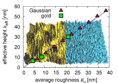
We can tune the width of the distribution and the average height . By scaling with we obtain geometrically similar geometries. This similarity is important because the effective height scales with the average roughness in the case of geometrical similarity bib:jens-kunert:2007b . We investigate Gaussian distributed heights with different widths and find that the height of the effective wall depends linearly on in the observed range bib:jens-kunert:2008c . Further, we find that the slip diverges as the amplitude of the roughness increases and the flow field gets more restricted which highlights the importance of a proper treatment of surface variations in very confined geometries bib:jens-kunert:2007b .
4 Structured surfaces with entrapped microbubbles
A natural continuation of our previous works on roughness induced apparent boundary slip and the collaboration mentioned above is the analysis of flow along superhydrophobic surfaces bib:jens-jari:2008 . While in typical experiments, slip lengths of a few tens of nanometers can be observed, it would be preferable for technical applications to increase the throughput of fluid in a microchannel, i.e., to obtain substantially larger slip. Superhydrophobic surfaces are promising in this context, since it has been recently predicted bib:cottin-bizone-etall-03 and experimentally reported bib:perot-rothstein-04 that the so-called Fakir effect or Cassie state considerably amplifies boundary slippage. Using highly rough hydrophobic surfaces such a situation can be achieved. Instead of entering the area between the rough surface elements, the liquid remains at the top of the roughness and traps air in the interstices. Thus, a very small liquid-solid contact area is generated.
Steinberger et al. utilized surfaces patterned with a square array of cylindrical holes to demonstrate that gas bubbles present in the holes may cause a reduced slip bib:steinberger-cottin-bizonne-kleimann-charlaix:2007 . Numerically, they found even negative slip lengths for flow over such bubble mattresses, i.e., the effective no-slip plane is inside the channel and the bubbles increase the flow resistance. In this section we consider negative slip lengths on bubble surfaces and also discuss the question of shear-rate dependent slip. In particular we show that microbubbles can generate a shear-rate dependence.
Our simulations utilize the single component multiphase LB model by Shan and Chen bib:shan-chen-liq-gas which enables simulations of liquid-vapor systems with surface tension. We are not aware of further lattice Boltzmann simulations to study the flow over a bubble mattress. However, a number of authors has applied various LB multiphase and multicomponent models to study the properties of droplets on chemically patterned and superhydrophobic surfaces kusumaatmaja-06 ; bib:kusumaatmaja-yeomans-2007 ; bib:pirat-etal-2008 ; bib:hyvaluoma-koponen-raiskinmaki-timonen:2007 . The flow in our system is confined between two parallel walls. One of the walls is patterned with holes and vapor bubbles are trapped to these holes. The other wall is smooth and moved with velocity . Steinberger et al. bib:steinberger-cottin-bizonne-kleimann-charlaix:2007 presented finite-element simulations of flow over rigid “bubbles” by applying slip boundaries at static bubble surfaces. The LB method allows the bubbles to deform if the viscous forces are high enough compared to the surface tension. We are also interested in how surface patterning affects the slip properties of these surfaces, and how bubbles could be utilized to develop surfaces with special properties for microfluidic applications bib:jens-jari:2008 .
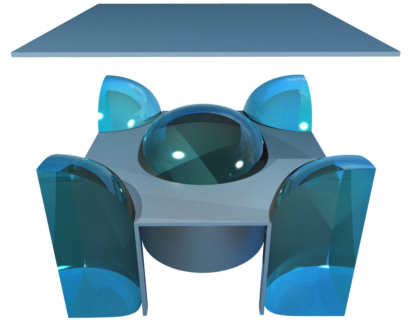
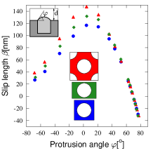
The distance between walls is m (40 lattice nodes) in all simulations, and the area fraction of holes is . A unit cell of the regular array is included in a simulation and periodic boundary condition are applied at domain boundaries. The bubbles are trapped to holes by using different wettabilities for boundaries in contact with the main channel and with the hole. The protrusion angle (see Fig. 5 for definition) is varied by changing the liquid’s bulk pressure. The effective slip length is , where is the shear stress acting on the upper wall and the dynamic viscosity of the liquid.
We investigate the effect of a modified protrusion angle and different surface patterns by using square, rectangular, and rhombic bubble arrays. The cylindrical holes have a radius nm and the area fraction of the holes is equal in all cases. The shear rate is such that the Capillary number . Here, and are the shear rate and surface tension, respectively. A snapshot of a simulation is shown in the left part of Fig. 5 and the slip lengths obtained are shown in the right part. The observed behavior is similar to that reported in bib:steinberger-cottin-bizonne-kleimann-charlaix:2007 , where a square array of holes was studied. In particular, we observe that when is large enough becomes negative. Moreover, when the protrusion angle equals zero, the slip length is maximised and the highest possible throughput in a microchannel is obtained. The behavior of the slip length can be explained by thinking of an increased surface roughness if the protrusion angle is larger or smaller than zero. Since the area fraction of the bubbles is the same in all three cases, our results clearly indicate that slip properties of the surface can be tailored not only by changing the protrusion angle but also by the array geometry. In the presented study, the highest slip lengths are obtained for the rhombic unit cell and it is current work of progress to investigate the influence of the array geometry in more detail. Recently, our findings have been confirmed theoretically by Davis and Lauga bib:davis-lauga-2009 .
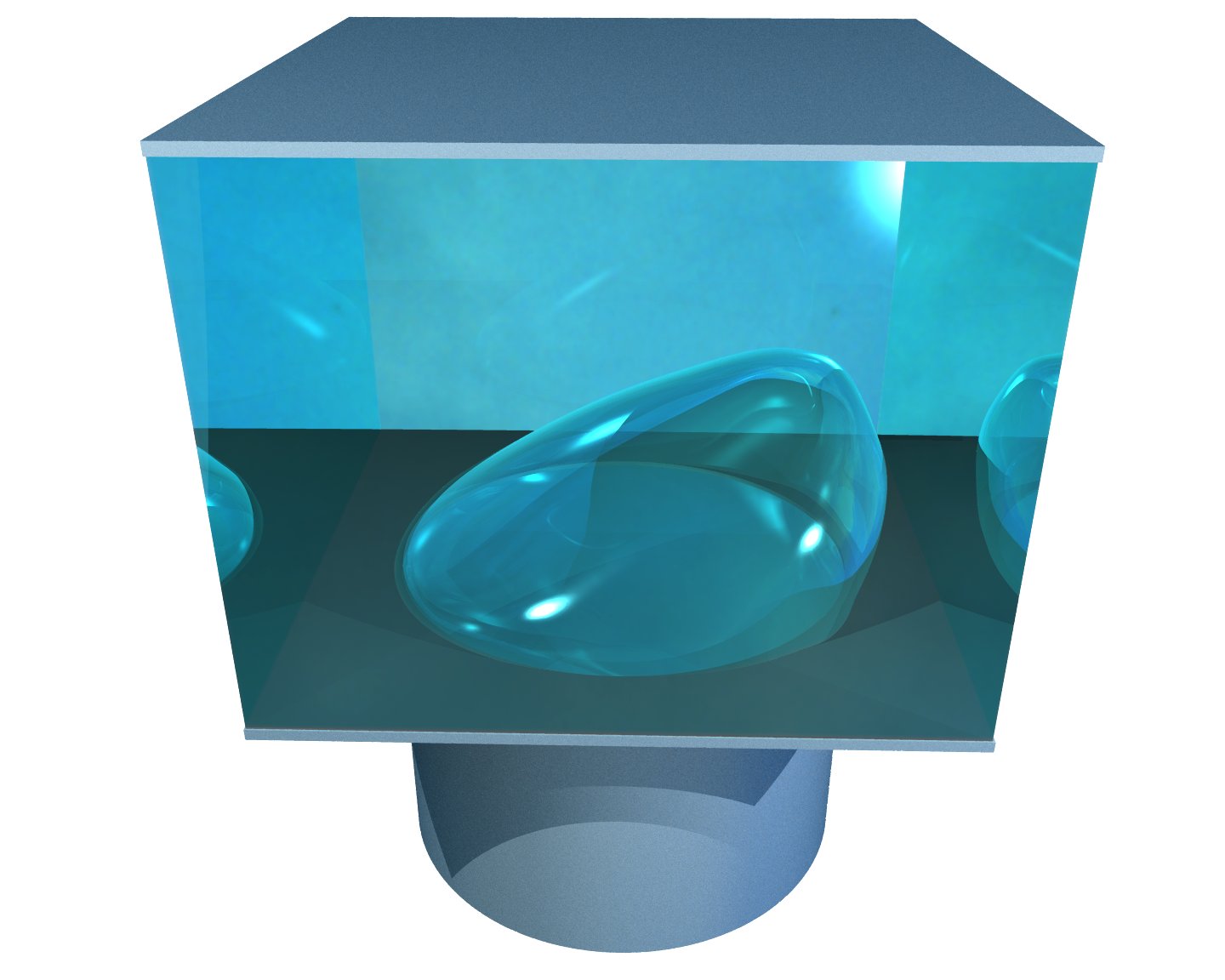
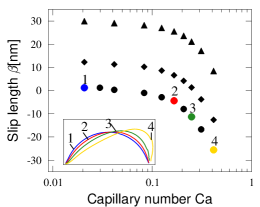
Next, the shear-rate dependence of the slip length is investigated. As the shear rate and thus the viscous stresses grow the bubbles are deformed (see Fig. 6, left) and the flow field is modified. In the central part of Fig. 6, we show the simulated slip length as a function of the Capillary number for three different protrusion angles. The Capillary numbers chosen are in higher end of the experimentally available range. Our results show shear-rate dependent slip, but the behavior is opposite to that found in some experiments: in fact, the slip lengths measured by us decrease with increasing shear due to a deformation of the bubbles. In the experiments, surface force apparatuses are used (see, e.g., Ref. bib:zhu-granick-01 ), where a strong increase in the slip is observed after some critical shear rate. This shear-rate dependence has been explained, e.g., with formation and growth of bubbles bib:degennes-02 ; lauga-brenner-04 . In our simulations, there is no formation or growth of the bubbles as we only simulate a steady case for given bubbles. The experiments on the other hand are dynamic. However, our results indicate that the changes in the flow field which occur due to the deformation of the bubbles cannot be an explanation for the shear-rate dependence observed in some experiments. Our results are consistent with bib:jens-kunert:2007b and the previous section, where it is shown that smaller roughness leads to smaller values of a detected slip. In the present case, the shear reduces the average height of the bubbles and thus the average scale of the roughness decreases as well.
Finally, we consider a surface patterned with grooves. Cylindrical bubbles protrude to the flow channel from these holes with protrusion angle , and the area fraction of slots is 0.53. We apply shear both parallel and perpendicular to the slots. The slip length is strongly dependent on the flow direction bib:jens-jari:2008 . For parallel flow the slip length is positive, but for the perpendicular case it becomes negative. Flow direction affects also greatly on the shear-rate dependence (cf. Fig. 6, right). When flow is parallel to the grooves no shear-rate dependence is observed, but for the perpendicular case this dependence is similar to that seen on hole arrays. These results can be understood on the basis of deforming bubbles. For perpendicular flow the bubbles are able to deform, but for the parallel case the bubbles retain their shape regardless of the shear rate.
5 Conclusion
In this paper we review applications of the lattice Boltzmann method to microfluidic problems. The main focus of the paper is on our own research related to the validation of the no-slip boundary condition. By introducing a model for hydrophobic fluid-surface interactions and studying pressure-driven flow in microchannels, we show that an experimentally detected slip can have its origin in hydrophobic interactions, but is constant with varied shear rates and decreases with increasing pressure. Another effect that was not fully understood so far is the influence of surfaces roughness. We are able to apply our simulations to surface data obtained from AFM measurements of experimental samples. We show that ignoring roughness can lead to large errors in a detected slip. In fact, we propose that roughness alone could often be the reason for apparent boundary slip.
Microscale bubbles at surfaces allow to tailor the slip properties of a surface. Such a surface with bubbles may yield negative slip, i.e., increased resistance to flow, if bubbles are strongly protruding to the channel. The lattice Boltzmann simulations capture the deformability of bubbles and thus allow to study the influence of the shear rate on the deformation of the interface and it’s effect on the measured slip. We find that the slip decreases with increasing shear rate demonstrating that shear induced bubble deformation cannot explain recent experimental findings where slip increases with increasing shear rate.
In the current review, we also demonstrate the suitability of the lattice Boltzmann method for modeling microfluidic applications: in contrast to molecular dynamics, it is able to reach experimentally available time and length scales. This allows one to compare simulation results to experimental data directly as demonstrated in the case of simulations of flow along surface data obtained from AFM measurements of “real” samples.
ACKNOWLEDGEMENTS
This work was financed within the DFG priority program “nano- and microfluidics”, the collaborative research center 716, the German academic exchange service (DAAD), and by the “Landesstiftung Baden-Württemberg”. We thank the Neumann Institute for Computing, Jülich and the Scientific Supercomputing Center, Karlsruhe for providing the computing time and technical support for the presented work. Jyrki Hokkanen (CSC – Scientific Computing Ltd., Espoo, Finland) is gratefully acknowledged for the bubble visualizations. Christian Kunert acknowledges fruitful discussions with P. Szymczak.
References
- (1) P. Tabeling. Introduction to microfluidics. Oxford University Press, 2005.
- (2) E. Lauga, M. P. Brenner, and H. A. Stone. Microfluidics: the no-slip boundary condition, in handbook of experimental fluid dynamics, chapter 15. Springer, 2005.
- (3) M. Knudsen. Experimentelle Bestimmung des Druckes gesättigter Quecksilberdämpfe bei 0o und höheren Temperaturen. Ann. d. Phys., 29:179, 1909.
- (4) V. S. J. Craig, C. Neto, and D. R. M. Williams. Shear dependent boundary slip in an aqueous Newtonian liquid. Phys. Rev. Lett., 87(5):054504, 2001.
- (5) D. C. Tretheway and C. D. Meinhart. A generating mechanism for apparent fluid slip in hydrophobic microchannels. Phys. Fluids, 16(5):1509, 2004.
- (6) J. T. Cheng and N. Giordano. Fluid flow throug nanometer scale channels. Phys. Rev. E, 65:031206, 2002.
- (7) C. H. Choi, K. J. Westin, and K. S. Breuer. Apparent slip in hydrophilic and hydrophobic microchannels. Phys. Fluids, 15(10):2897, 2003.
- (8) J. Baudry and E. Charlaix. Experimental evidance for a large slip effect at a nonwetting fluid-solid interface. Langmuir, 17:5232, 2001.
- (9) C. Cottin-Bizonne, S. Jurine, J.Baudry, J. Crassous, F. Restagno, and E. Charlaix. Nanorheology: an investigation of the boundary condition at hydrophobic and hydrophilic interfaces. Eur. Phys. J. E, 9:47, 2002.
- (10) O. I. Vinogradova and G. E. Yakubov. Dynamic effects on force mesurements. 2. lubrication and the atomic force microscope. Langmuir, 19:1227, 2003.
- (11) O. I. Vinogradova. Drainage of a thin film confined between hydrophobic surfaces. Langmuir, 11:2213, 1995.
- (12) P. Gennes. On fluid/wall slippage. Langmuir, 18:3413, 2002.
- (13) S. Succi. Mesoscopic modeling of slip motion at fluid-solid interfaces with heterogeneous catalysis. Phys. Rev. Lett., 89(6):064502, 2002.
- (14) J. L. Barrat and L. Bocquet. Large slip effect at a nonwetting fluid interface. Phys. Rev. Lett., 82(23):4671, 1999.
- (15) M. Cieplak, J. Koplik, and J. R. Banavar. Boundary conditions at a fluid-solid interface. Phys. Rev. Lett., 86:803, 2001.
- (16) P. A. Thompson and S. Troian. A general boundary condition for liquid flow at solid surfaces. Nature, 389:360, 1997.
- (17) D. C. Tretheway, L. Zhu, L. Petzold, and C. D. Meinhart. Examination of the slip boundary condition by micro-PIV and lattice Boltzmann simulations. Proc. of IMECE, 2002.
- (18) C. Neto, D. R. Evans, E. Bonaccurso, H. J. Butt, and V. S. J. Craig. Boundary slip in Newtonian liquids: a review of experimental studies. Rep. Prog. Phys., 68:2859, 2005.
- (19) L. Bocquet and J. L. Barrat. Flow boundary conditions from nano- to micro-scales. Soft Matter, 3:685, 2007.
- (20) N. V. Churaev, V. D. Sobolev, and A. N. Somov. Slippage of liquids over lyophobic solid surfaces. J. Colloid Int. Sci., 97:574, 1984.
- (21) Y. Zhu and S. Granick. Rate-dependent slip of Newtonian liquid at smooth surfaces. Phys. Rev. Lett., 87:096105, 2001.
- (22) C. L. M. H. Navier. Mémoire sur les lois du mouvement de fluids. Mem. Acad. Sci. Ins. Fr., 6:389, 1823.
- (23) J. Koplik, J. R. Banavar, and J. F. Willemsen. Molecular dynamics of fluid flow at solid-surfaces. Phys. Fluids, 1:781, 1989.
- (24) P. A. Thompson and M. O. Robbins. Shear flow near solids: epitaxial order and flow boundary conditions. Phys. Rev. A, 41:6830, 1990.
- (25) G. Nagayama and P. Cheng. Effects of interface wettability on microscale flow by molecular dynamics simulation. Int. J. Heat Mass Transfer, 47:501, 2004.
- (26) D. C. Tretheway and C. D. Meinhart. Apparent fluid slip at hydrophobic microchannel walls. Phys. Fluids, 14:L9, 2002.
- (27) O. I. Vinogradova. Possible implications of hydrophopic slippage on the dynamic measurements of hydrophobic forces. J. Phys. Condens. Matter, 8:9491, 1996.
- (28) C. Cottin-Bizonne, C. Barentin, E. Charlaix, L. Bocquet, and J. L. Barrat. Dynamics of simple liquids at heterogeneous surfaces: molecular dynamics simulations and hydrodynamic description. Eur. Phys. J. E, 15:427, 2004.
- (29) N. V. Priezjev, A. Darhuber, and S. Troian. Slip behavior in liquid films on surfaces of patterned wettability: comparison between continuum and molecular dynamics simulations. Phys. Rev. E, 71:041608, 2005.
- (30) S. Succi. The lattice Boltzmann equation for fluid dynamics and beyond. Oxford University Press, 2001.
- (31) D. Tretheway, L. Zhu, L. Petzold, and C. Meinhart. Examination of the slip boundary condition by u-piv and lattice Boltzmann simulation. In 2002 ASME International Mechanical Engineering Congress & Exposition, New Orleans, Louisiana, 2002.
- (32) G. H. Tang, W. Q. Tao, and Y. L. He. Lattice Boltzmann method for gaseous microflows using kinetic theory boundary conditions. Phys. Fluids, 17:058101, 2005.
- (33) M. Sbragaglia and S. Succi. Analytical calculation of slip flow in lattice Boltzmann models with kinetic boundary conditions. Phys. Fluids, 17:093602, 2005.
- (34) S. Ansumali and I. V. Karlin. Kinetic boundary conditions in the lattice boltzmann method. Phys. Rev. E, 66:026311, 2002.
- (35) V. Sofonea and R. F. Sekerka. Diffuse-reflection boundary conditions for a thermal lattice Boltzmann model in two dimensions: Evidence of temperature jump and slip velocity in microchannels. Phys. Rev. E, 71:066709, 2005.
- (36) X. D. Niu, C. Shu, and Y. T. Chew. A lattice Boltzmann BGK model for simulation of micro flows. Europhys. Lett., 67:600, 2004.
- (37) Z. Guo, B. Shi, T. S. Zhao, and C. Zheng. Discrete effects on boundary conditions for the lattice boltzmann equation in simulating microscale gas flows. Phys. Rev. E, 76:056704, 2007.
- (38) X. Nie, G. D. Doolen, and S. Chen. Lattice-Boltzmann simulations of fluid flows in mems. J. Stat. Phys., 107(112):279, 2002.
- (39) L. Zhu, D. Tretheway, L. Petzold, and C. Meinhart. Simulation of fluid slip at 3d hydrophobic microchannel walls by the lattice Boltzmann method. J. Comp. Phys., 202:181, 2005.
- (40) R. Benzi, L. Biferale, M. Sbragaglia, S. Succi, and F. Toschi. Mesoscopic two-phase model for describing apparent slip in micro-channel flows. Europhys. Lett., 74:651, 2006.
- (41) J. Zhang and D. Y. Kwok. Apparent slip over a solid-liquid interface with a no-slip boundary condition. Phys. Rev. E, 70:056701, 2004.
- (42) R. Benzi, L. Biferale, M. Sbragaglia, S. Succi, and F. Toschi. Mesoscopic modeling of a two-phase flow in the presence of boundaries: the contact angle. Phys. Rev. E, 74:021509, 2006.
- (43) H. Huang, D. T. Thorne, M. G. Schaap, and M. C. Sukop. Proposed approximation for contact angles in shan-and-chen-type multicomponent multiphase lattice boltzmann models. Phys. Rev. E, 76:066701, 2007.
- (44) P. L. Bhatnagar, E. P. Gross, and M. Krook. Model for collision processes in gases. I. small amplitude processes in charged and neutral one-component systems. Phys. Rev., 94(3):511, 1954.
- (45) X. Shan and H. Chen. Lattice Boltzmann model for simulating flows with multiple phases and components. Phys. Rev. E, 47(3):1815, 1993.
- (46) X. Shan and H. Chen. Simulation of nonideal gases and liquid-gas phase transitions by the lattice Boltzmann equation. Phys. Rev. E, 49(4):2941, 1994.
- (47) J. Harting, C. Kunert, and H. Herrmann. Lattice Boltzmann simulations of apparent slip in hydrophobic microchannels. Europhys. Lett., pp 328–334, 2006.
- (48) J. Horbach and S. Succi. Lattice Boltzmann versus molecular dynamics simulation of nanoscale hydrodynamic flows. Phys. Rev. Lett., 96:224503, 2006.
- (49) S. Chibbaro, L. Biferale, F. Diotallevi, S. Succi, K. Binder, D. Dimitrov, A. Milchev, S. Girardo, and D. Pisignano. Evidence of thin-film precursors formation in hydrokinetic and atomistic simulations of nano-channel capillary filling. Europhys. Lett., 84:44003, 2008.
- (50) C. Neto, V. S. J. Craig, and D. R. M. Williams. Evidence of shear-dependent boundary slip in Newtonian liquids. Eur. Phys. J. E, 12:71, 2003.
- (51) C. Kunert and J. Harting. On the effect of surfactant adsorption and viscosity change on apparent slip in hydrophobic microchannels. Progress in CFD, 8:197, 2008.
- (52) C. Kunert and J. Harting. Simulation of fluid flow in hydrophobic rough micro channels. Int. J. Comp. Fluid Dyn., 22:475, 2008.
- (53) S. Richardson. On the no-slip boundary condition. J. Fluid Mech., 59:707, 1973.
- (54) G. McHale and M. I. Newton. Surface roughness and interfacial slip boundary condition for quarzcrystal microbalances. J. Appl. Phys., 95:373, 2004.
- (55) A. Jabbarzadeh, J. D. Atkinson, and R. I. Tanner. Effect of the wall roughness on slip and rheological properties of hexadecane in molecular dynamics simulation of couette shear flow between two sinusoidal walls. Phys. Rev. E, 61:690, 2000.
- (56) M. Sbragaglia, R. Benzi, L. Biferale, S. Succi, and F. Toschi. Surface roughness-hydrophobicity coupling in microchannel and nanochannel flows. Phys. Rev. Lett., 97:204503, 2006.
- (57) A. Al-Zoubi and G. Brenner. Simulating fluid flow over sinusoidal surfaces using the lattice boltzmann method. Computers & Mathematics with Applications, 55:1365, 2008.
- (58) F. Varnik and D. Raabe. Scaling effects in microscale fliuid flows at rough solid surfaces. Modelling Simul. Mater Sci Eng., 14:857, 2006.
- (59) F. Varnik, D. Dorner, and D. Raabe. Roughness-induced flow instability: a lattice Boltzmann study. J. Fluid Mech., 573:191, 2006.
- (60) C. Kunert and J. Harting. Roughness induced apparent boundary slip in microchannel flows. Phys. Rev. Lett., 99:176001, 2007.
- (61) N. Lecoq, R. Anthore, B. Cickhocki, P. Szymczak, and F. Feuillebois. Drag force on a sphere moving towards a corrugated wall. J. Fluid Mech., 513:247, 2004.
- (62) O. I. Vinogradova and G. E. Yakubov. Surface roughness and hydrodynamic boundary conditions. Phys. Rev. E, 73:045302(R), 2006.
- (63) J. Hyväluoma and J. Harting. Slip flow over structured surfaces with entrapped microbubbles. Phys. Rev. Lett., 100:246001, 2008.
- (64) C. Cottin-Bizonne, J. L. Barrat, L. Bocquet, and E. Charlaix. Low-friction flows of liquid at nanopatterned interfaces. Nature Materials, 2:237, 2003.
- (65) O. J. Perot and J. P. Rothstein. Laminar drag reduction in microchannels using ultrahydrophobic surfaces. Phys. Fluids, 16:4635, 2004.
- (66) A. Steinberger, C. Cottin-Bizonne, P. Kleimann, and E. Charlaix. High friction on a bubble mattress. Nature Materials, 6:665, 2007.
- (67) H. Kusumaatmaja, J. Leopoldes, A. Dupuis, and J. M. Yeomans. Drop dynamics on chemicaly patterned surfaces. Europhys. Lett., 73:740, 2006.
- (68) H. Kusumaatmaja and J. M. Yeomans. Modeling contact angle hysteresis on chemically patterned and superhydrophobic surfaces. Langmuir, 23:6019, 2007.
- (69) C. Pirat, M. Sbragaglia, A. M. Peters, B. M. Borkent, R. G. H. Lammertink, M. Wesseling, and D. Lohse. Multiple time scale dynamics in the breakdown of superhydrophobicity. Europhys. Lett., 81:66002, 2008.
- (70) J. Hyväluoma, A. Koponen, P. Raiskinmäki, and J. Timonen. Droplets on inclined rough surfaces. Eur. Phys. J. E, 23:289, 2007.
- (71) A. M. J. Davis and E. Lauga. Geometric transition in friction for flow over a bubble mattress. Phys. Fluids, 21:011701, 2009.
- (72) E. Lauga and M. P. Brenner. Dynamic mechanism for aparrent slip on hydrophobic surfaces. Phys. Rev. E, 70:026311, 2004.