Multi-twist optical Möbius strips
Abstract
Circularly polarized Gauss-Laguerre and laser beams that cross at their waists at a small angle are shown to generate a quasi-paraxial field that contains an axial line of circular polarization, a C line, surrounded by polarization ellipses whose major and minor axes generate multi-twist Möbius strips with twist numbers that increase with distance from the C point. These Möbius strips are interpreted in terms of Berry’s phase for parallel transport of the ellipse axes around the C point.
OCIS codes: 260.0260, 260.5430, 260.6042, 140.3460.
We show here how to create quasi-paraxial, elliptically polarized light fields in which the major and minor axes of the polarization ellipses generate Möbius strips with radially increasing numbers of half-twists; to our knowledge, these polarization structures are unique.
The polarization ellipses in elliptically polarized paraxial fields lie in parallel planes (here the -plane) oriented normal to the propagation direction (-axis). The generic point polarization singularity in any plane of such a field is a C point, an isolated point of circular polarization embedded in a field of polarization ellipses []. The azimuthal orientation of a circle is undefined (singular), and as a result the polarization ellipses surrounding a C point rotate about the point, generically with winding number (net rotation angle/) . As the beam propagates in space the C point traces out a line, a C line [].
When the beam opens up and is no longer paraxial, the polarization ellipses are no longer constrained to lie in parallel planes; C lines, however, remain. In any plane pierced by a C line a C point appears, and the projections onto the plane of the surrounding ellipses continue to rotate about the point with winding number, or topological charge, .
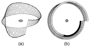
What is the full, three-dimensional (3D) arrangement of the ellipses that surround a C line in a non-paraxial field? The (possibly surprising) answer is that the major and minor axes of these ellipses generate Möbius strips []. The canonical Möbius strip has a single half-twist, and can be either right-handed (RH) or left-handed (LH). Such strips have recently been shown [] to occur naturally in random fields. Illustrated in Fig. 1 is an example of a left-handed Möbius strip. In random fields left- and right-handed strips are equally probable.
Möbius strips with a larger, odd number of half-twists are possible, and strips with three half-twists are also found in random fields []; in such fields of all Möbius strips have one half-twist, the remainder three half-twists. Optical Möbius strips with more than three half-twists, although not forbidden topologically, do not occur naturally.
Can such strips be generated? The answer is yes, and we show here how to combine two laser beams to create a quasi-paraxial, elliptically polarized beam containing a C line surrounded by polarization ellipses whose major and minor axes generate Möbius strips with large numbers of half-twists.
An elliptically polarized paraxial laser beam containing an axial C line can be generated by a coaxial, coherent superposition of a circularly polarized RH (LH) Gauss-Laguerre mode and a circularly polarized LH (RH) mode. The LH (RH) mode contains a central optical vortex (phase singularity) at which the amplitude vanishes [], so at that point the polarization in the combined beam is RH (LH) circular. At other points in the beam RH and LH components combine to produce elliptical polarization.
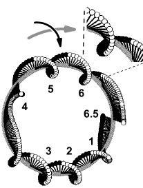
Within the paraxial approximation, at the waists of the individual beams, and therefore at the waist of the combined beam, there exist only the two transverse field components and . However, if the two beams are made to intersect in the -plane at small angles relative to the -axis, a third field component develops. At its waist, the resulting field, described quantitatively below, has the following unique property: Surrounding the central C point are circular rings of radius on which the major and minor axes of the polarization ellipses generate multi-twist Möbius strips that contain an odd number of half-twists; these strips have the unique property that the number of half-twists increases with radial distance from the C point!
In Fig. 2 we show an example of such a Möbius strip. In principle, , and therefore the number of half-twists, increases without limit; in practice, of course, the Gaussian envelope of the beam reduces the intensity to immeasurably small levels far from the beam center.
We turn now to a quantitative description of these multi-twist optical Möbius strips. For the sake of definiteness, we take the mode to be to be RH and the vortex containing mode to be left handed. We assume that both beams have the same wavelength , and the same waist parameter , and that they intersect maximally at their waists which are centered on the origin. Although there are a number of different experimental approaches to generating such beams, the one most likely to be used involves liquid crystal modulators. These are usually addressed as a Cartesian grid of pixels, and so in what follows we use Cartesian coordinates.
We define a Gaussian envelope function for a beam, , by
| (1) |
where . Writing for the angle that the beam makes with the -axis,
| (2) |
The field components of the combined beam , with unit vectors along the corresponding coordinate axes, are
| (3) |
where
| (4a) | ||||
| (4b) | ||||
| (4c) | ||||
In Eqs. (4b) and (4c) () for a positive (negative) vortex. For all figures presented here, , , and .
The major axis and minor axis of the ellipses surrounding the C point in Figs. 1 and 2 (and Figs. 3 and 4 below), are obtained from Berry’s formulas []: , .
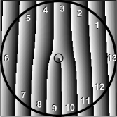
The exact dependence of the number of half-twists and handedness of the Möbius strips requires an analyses that is too complicated to describe here. Instead, insight into what happens can be obtained by considering the angle shown in Fig. 3, where and are the -components of . Because is a line, not a vector, it is plotted modulo . On the small circle at the center of the figure winds around the central C point, which in such plots appears as a vortex, with winding number : because along a counterclockwise, by convention positive, circuit, decreases by .
The corresponding Möbius strip, shown in Fig. 1, can be interpreted in terms of Berry’s phase []: as one moves along the circle surrounding the C point, undergoes parallel transport, rotating through during one complete circuit; this leads to winding number in the -projection, and the one-half-twist Möbius strip in 3D.
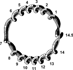
In addition to the central C point, Fig. 3 contains a number of -fringes that are analogous to the -fringes in the forked-fringe method for measuring vortices []. Each time passes through a -fringe it rotates through , so that the total number of half-twists equals the total number of fringes traversed during a circuit about the C point. The large circle in Fig. 3 that passes through -fringes corresponds to the Möbius strip in Fig. 2, which has half-twists. Similar considerations apply to axis , and in Fig. 4 we show a Möbius strip generated by this axis which has half-twists ( full twists).
The forgoing leads to a simple, heuristic expression for twist number , the number of full twists, as a function of the radial distance from the C point. For , far from the C point the fringe spacing along the here horizontal -axis, is , so that the number of fringes traversed by a line of length , the circle diameter, is . On a circle centered on the C point the circumference passes through each fringe twice, and upon adding in the extra -fringe induced by the C point we obtain
| (5) |
In Fig. 1, , , in Fig. 2, , , and in Fig. 4, , in each case in agreement with Eq. (5). We find Eq. (5) to be in general agreement with our computer simulations for ; for larger , begins to decrease significantly with increasing due to wavefront curvature and the Gouy phase shift, and Eq. (5) underestimates the twist number.
To be reported on elsewhere are the twist number and handedness of the Möbius strips as a function of and other system parameters, the -foil knots generated by the axis endpoints of -twist Möbius strips, the strips (twisted ribbons) with an even number of half-twists that appear on circles that do not enclose a C point, the multi-twist optical Möbius strips that are generated by other combinations of laser modes, and by other beam configurations, and the dependence of these structures.
In summary, we have shown how to combine two circularly polarized laser beams, one of which contains a vortex, to create a quasi-paraxial field containing a central C point surrounded by polarization ellipses whose major and minor axes generate multi-twist optical Möbius strips with twist numbers that increase radially from the C point. These Möbius strips are structurally stable, changing unimportantly when, for example, noise is added to the simulation. Coherent nanoprobe techniques [] capable of determining the field structure on subwavelength scales should permit experimental measurements of these highly unusual objects. As for possible applications, we note, inter alia, that the Möbius strips could be embedded in polarization sensitive photoresists to create devices with unique optical properties.
email address: freund@mail.biu.ac.il (I. Freund).
References
[1] J. F. Nye, Natural Focusing and Fine Structure of Light (IOP Publ., Bristol, 1999).
[2] J. F. Nye, Proc. Roy. Soc. Lond. A 389, 279290 (1983).
[3] M. V. Berry and M. R. Dennis, Proc. Roy. Soc. Lond. A 457, 141155 (2001).
[4] M. R. Dennis, Opt. Commun. 213, 201221 (2002).
[5] M. V. Berry, J. Opt. A 6, 675678 (2004).
[6] I. Freund, “Optical Möbius strips in three-dimensional ellipse fields: I. Lines of circular polarization,” Opt. Commun. in press, doi:10.1016/j.optcom.2009.09.042 (2009).
[7] M. S. Soskin and M. V. Vasnetsov, “Linear theory of optical vortices,” in Optical Vortices, M. Vasnetsov and K. Staliunas Eds., Horizons in World Physics 228, 135 (Nova Science Publs., Commack, New York, 1999).
[8] An excellent review of Berry’s phase in optics in given in E. J. Galvez, “Applications of geometric phase in optics,” available from Wikipedia (Berry’s phase), or http://departments.colgate.edu/physics/faculty/galvez.htm.
[9] N. B. Baranova, B. Ya Zel’dovich, A. V. Mamaev, N. Pilipetskii, and V. V. Shkukov, JETP Lett. 33, 195199 (1981).
[10] I. V. Basistiy, M. S. Soskin, and M. V. Vasnetsov, Opt. Commun. 119, 604612 (1995).
[11] R. Dandliker, I. Marki, M. Salt, and A. Nesci, J. Optics A 6, S189S196 (2004).
[12] P. Tortora, R. Dandliker, W. Nakagawa, and L. Vaccaro, Opt. Commun. 259, 876882 (2006).
[13] C. Rockstuhl, I. Marki, T. Scharf, M. Salt, H. P. Herzig, and R. Dandliker, Current Nanoscience 2, 337350 (2006).
[14] P. Tortora, E. Descrovi, L. Aeschimann, L. Vaccaro, H. P. Herzig, and R. Dandliker, Ultramicroscopy 107, 158165 (2007).
[15] K. G. Lee, H. W. Kihm, J. E. Kihm, W. J. Choi, H. Kim, C. Ropers, D. J. Park, Y. C. Yoon, S. B. Choi, H. Woo, J. Kim, B. Lee, Q. H. Park, C. Lienau C, and D. S. Kim, Nature Photonics 1, 5356 (2007).
[16] Z. H. Kim and S. R. Leone, Opt. Express 16, 17331741 (2008).
[17] R. J. Engelen, D. Mori, T. Baba, and L. Kuipers, Phys. Rev. Lett. 102, 023902 (2009);Erratum: ibid. 049904 (2009).
[18] M. Burresi, R. J. Engelen, A. Opheij, D. van Oosten, D. Mori, T. Baba, and L. Kuipers, Phys. Rev. Lett. 102, 033902 (2009).
References with titles
[1] J. F. Nye, Natural Focusing and Fine Structure of Light (IOP Publ., Bristol, 1999).
[2] J. F. Nye, “Lines of circular polarization in electromagnetic wave fields,” Proc. Roy. Soc. Lond. A 389, 279290 (1983).
[3] M. V. Berry and M. R. Dennis, “Polarization singularities in isotropic random vector waves,” Proc. Roy. Soc. Lond. A 457, 141155 (2001).
[4] M. R. Dennis, “Polarization singularities in paraxial vector fields: morphology and statistics,” Opt. Commun. 213, 201221 (2002).
[5] M. V. Berry, “Index formulae for singular lines of polarization,” J. Opt. A 6, 675678 (2004).
[6] I. Freund, “Optical Möbius strips in three-dimensional ellipse fields: I. Lines of circular polarization,” Opt. Commun. in press, doi:10.1016/j.optcom.2009.09.042 (2009).
[7] M. S. Soskin and M. V. Vasnetsov, “Linear theory of optical vortices,” in Optical Vortices, M. Vasnetsov and K. Staliunas Eds., Horizons in World Physics 228, 135 (Nova Science Publs., Commack, New York, 1999).
[8] An excellent review of Berry’s phase in optics in given in E. J. Galvez, “Applications of geometric phase in optics,” available from Wikipedia (Berry’s phase), or http://departments.colgate.edu/physics/faculty/galvez.htm.
[9] N. B. Baranova, B. Ya Zel’dovich, A. V. Mamaev, N. Pilipetskii, and V. V. Shkukov, “Dislocations of the wave-front of a speckle-inhomogeneous field (theory and experiment),” JETP Lett. 33, 195199 (1981).
[10] I. V. Basistiy, M. S. Soskin, and M. V. Vasnetsov, “Optical wavefront dislocations and their properties,” Opt. Commun. 119, 604612 (1995).
[11] R. Dandliker, I. Marki, M. Salt, and A. Nesci, “Measuring optical phase singularities at subwavelength resolution,” J. Optics A 6, S189S196 (2004).
[12] P. Tortora, R. Dandliker, W. Nakagawa, and L. Vaccaro, “Detection of non-paraxial optical fields by optical fiber tip probes,” Opt. Commun. 259, 876882 (2006).
[13] C. Rockstuhl, I. Marki, T. Scharf, M. Salt, H. P. Herzig, and R. Dandliker, “High resolution interference microscopy: A tool for probing optical waves in the far-field on a nanometric length scale,” Current Nanoscience 2, 337350 (2006).
[14] P. Tortora, E. Descrovi, L. Aeschimann, L. Vaccaro, H. P. Herzig, and R. Dandliker, “Selective coupling of HE11 and TM01 modes into microfabricated fully metal-coated quartz probes,” Ultramicroscopy 107, 158165 (2007).
[15] K. G. Lee, H. W. Kihm, J. E. Kihm, W. J. Choi, H. Kim, C. Ropers, D. J. Park, Y. C. Yoon, S. B. Choi, H. Woo, J. Kim, B. Lee, Q. H. Park, C. Lienau C, and D. S. Kim, “Vector field microscopic imaging of light,” Nature Photonics 1, 5356 (2007).
[16] Z. H. Kim and S. R. Leone, “Polarization-selective mapping of near-field intensity and phase around gold nanoparticles using apertureless near-field microscopy,” Opt. Express 16, 17331741 (2008).
[17] R. J. Engelen, D. Mori, T. Baba, and L. Kuipers, “Subwavelength Structure of the Evanescent Field of an Optical Bloch Wave,” Phys. Rev. Lett. 102, 023902 (2009); Erratum: ibid. 049904 (2009).
[18] M. Burresi, R. J. Engelen, A. Opheij, D. van Oosten, D. Mori, T. Baba, and L. Kuipers, “Observation of Polarization Singularities at the Nanoscale,” Phys. Rev. Lett. 102, 033902 (2009).