Waveguide-based OPO source of entangled photon pairs
Abstract
In this paper we present a compact source of narrow-band energy-time entangled photon pairs in the telecom regime based on a Ti-indiffused Periodically Poled Lithium Niobate (PPLN) waveguide resonator, i.e. a waveguide with end-face dielectric multi-layer mirrors. This is a monolithic doubly resonant Optical Parametric Oscillator (OPO) far below threshold, which generates photon pairs by Spontaneous Parametric Down Conversion (SPDC) at around 1560 nm with a 117 MHz (0.91 pm)-bandwidth. A coherence time of 2.7 ns is estimated by a time correlation measurement and a high quality of the entangled states is confirmed by a Bell-type experiment. Since highly coherent energy-time entangled photon pairs in the telecom regime are suitable for long distance transmission and manipulation, this source is well suited to the requirements of quantum communication.
1 Introduction
Long distance quantum communication is based on the transmission of entangled photons between remote parties. The transmission distance is currently limited by photonic absorption in optical fibre, which increases exponentially with distance. In order to overcome this limitation, quantum repeater protocols have been proposed [1, 2]. These protocols consist in the partition of the communication distance into smaller segments across which two quantum memories [3] can be efficiently entangled. By performing entanglement-swapping operations on the intermediate nodes, the entanglement is then transferred over the entire distance.
In such a scheme, a narrow-band entangled photon pair source is highly desirable. First of all, it allows the use of atomic quantum memories, whose spectral linewidths are at the MHz level. A further advantage of photons with a coherence time larger than typical detector resolution is that entanglement swapping can be performed between cw sources, i.e. without the need of synchronization [4]. Moreover, a high photons’ coherence time increases the tolerance of fibre length fluctuations and chromatic dispersion.
In order to generate efficient sources of entangled photon pairs, SPDC in nonlinear crystals is more practical with respect to other techniques, such as intracavity atomic ensembles [5] and bi-exciton cascade emission of quantum dots [6, 7]. However, since SPDC sources produce broad frequency spectra (of the order of THz), the photons’ bandwidth needs to be reduced. Placing a nonlinear crystal inside an optical cavity, in order to realize OPO-based sources of narrow-band entangled photon pairs, is a recent approach for overcoming the limits of SPDC ([8, 9, 10, 11, 12, 13, 14]). In these systems the bandwidth of the emitted photons is limited by the cavity and, at the same time, the down conversion process is enhanced with respect to the single pass scheme [8, 9].
The OPO sources reported so far produced photon pairs in the visible regime between 700 and 900 nm with bandwidths in the MHz level, comparable to the typical linewidth of atomic quantum memories. In [13] a narrow band single-mode polarization-entangled photon source with a linewidth of 9.6 MHz at 780 nm was reported. Only recently [14] the first long-term stable photon pairs OPO source, with a linewidth of 3 MHz at 894.3 nm, was made. The schemes reported so far generate polarization entangled photons in the visible spectrum, which are not suitable for long distance quantum communication.
In this paper we present a source of narrow-band energy-time entangled photon pairs at telecom wavelength based on a Ti-indiffused PPLN waveguide resonator, i.e. a waveguide with end-face dielectric multi-layer mirrors reflective at telecom wavelengths. Our system is the first realization of a monolithic waveguide-based OPO far below threshold. The integrated optics approach has significant advantages with respect to bulk OPOs: due to the high intensity of the pump field with a good overlap to signal and idler modes even over long distances without any diffraction, a high non linear efficiency results, which may surpass that of a bulk source by orders of magnitude. Moreover, no cavity alignment is necessary and the resonant frequency can be kept stable by controlling the temperature of the waveguide [15]. In the first part of this paper we describe in detail the photon source, paying attention to the features of the frequency spectrum of the generated photons and to the stabilization of the double resonance condition. Then, we describe the performance of the photon pair source and characterize the generated energy-time entangled photon pairs by performing a Bell-type experiment in the configuration proposed by Franson [16]. The results are discussed in the conclusion.
2 The source
2.1 The Ti:PPLN waveguide resonator
A 3.6 cm long waveguide was fabricated by indiffusing (per 9 hours at a temperature of 1060 ∘C) a 6 m wide vacuum-deposited Ti-stripe of 98 nm thickness into the -Z- face of a Z-cut Lithium Niobate (LN) substrate [15]. These parameters were chosen to get a single mode waveguide (at around 1.55 m of wavelength) of low propagation losses ( 0.1 dB/cm) and a TM-mode distribution (4.3 2.9 m2, see Figure 1) of good overlap with the mode of standard telecom fibres. The latter enables low loss fibre coupling and would even allow fibre butt coupling in the future.
After waveguide fabrication, the sample was periodically poled with a periodicity of =16.6 m to get Quasi Phase-Matching (QPM) for SPDC at a pump wavelength of 780 nm and signal and idler wavelengths at 1.55 m.
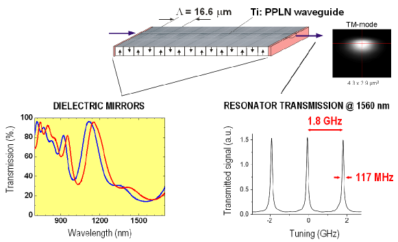
Figure 1 shows a photograph of the surface of such a waveguide; it is slightly etched to make the domain structure visible. The nearly 1:1 duty cycle of the domain pattern guarantees a high nonlinear efficiency.
Finally, a stable monolithic waveguide resonator was formed by depositing dielectric mirrors on the waveguide end-faces. They consist of alternating SiO2 and TiO2-layers with thicknesses defined by a Monte-Carlo optimization to get a high reflectivity at signal and idler wavelengths (here: 85%), but simultaneously a high transmission for the pump (here: 80%). Figure 1 shows on the lower left the two mirror characteristics measured on LN-substrates simultaneously coated with the waveguide end-faces.
The resonator was investigated by measuring its transmission versus the frequency of a tunable extended cavity laser ( 1560 nm). Figure 1 shows on the lower right a corresponding result. We observe a Free Spectral Range (FSR) of 1.8 GHz (14 pm) and a Full Width at Half Maximum (FWHM) of 117 MHz (0.91 pm), resulting in a finesse of 15.4. This value allows to evaluate the waveguide propagation losses as dB/cm at 1560 nm. The frequency spectrum of the resonator can be simply tuned by changing its temperature. In this way its length and the effective index of refraction are changed leading to a significant shift of the spectrum. We estimate a wavelength change of 44.5 pm/∘C (5.7 GHz/∘C). In other words, the shift from one cavity mode to another in the telecom region implies a change of about 0.3 ∘C at 1560 nm.
2.2 Setup
An external-cavity cw diode laser (Toptica DL100), stabilized on a Rubidium transition (D2 of 85Rb) at 780,027 nm, is used as a pump for producing photon pairs by SPDC from the PPLN waveguide resonator (Figure 2).
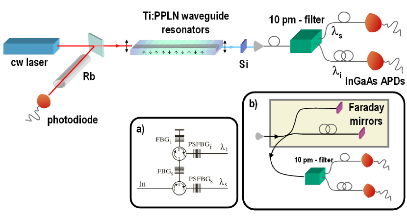
At a temperature of 128.6 ∘C the conditions of QPM and energy conservation (for which , where (j=p,s,i) refers respectively to the pump, signal and idler frequency) are fulfilled for the generation of photon pairs at around 1560 nm. Signal and idler photons are preferentially emitted only if their frequencies also match the resonant modes of the cavity. Crucial for this goal is the possibility of properly adjusting the transmission spectrum of the resonator by changing the temperature of the sample. The constraint of double resonance affects the frequency spectrum of the photons emitted by the source. In the next subsection we shall describe in detail this spectrum and the method for achieving the double resonance condition at around 1560 nm.
The pump and the created photons are vertically polarized (type I eee coupling) and exit the waveguide resonator collinearly. A bulk high-pass Silicon filter (Si) is placed before coupling into the fibre in order to block the remaining pump light and has a transmission of 91% of the created photons. The signal and the idler photon are each in a distinct resonant cavity mode. We distinguish them using a filter (AOS GmbH) which selects two wavelengths symmetrically around the SPDC degeneracy wavelength (=1559.5 nm and =1561.5 nm) with a bandwidth of 10 pm (1.2 GHz). This value allows us to select only one cavity mode, as the FSR between them is about 14 pm (1.8 GHz). For the selection of each wavelength (see Figure 2, inset a)) a standard Fibre Bragg Grating (FBG) reflects the desired wavelength with a bandwidth of 1 nm and a circulator directs the reflected light to a Phase-Shifted Fibre Bragg Grating (PSFBG), which transmits the wavelength with a 10 pm-bandwidth, as already explained in detail in [17]. The insertion losses of this filter are 2.8 and 3.8 dB for the two selected wavelengths.
After being filtered, the photons are detected by two InGaAs Avalanche PhotoDiodes (APDs). One APD is in a free-running mode with 2.1% quantum efficiency, at which it has 600 dark-counts s-1, and 30 s dead time for reducing after-pulses, whereas the other one operates in gated mode (ID200, idQuantique) with a quantum efficiency of 7.8% and a dark-count probability of 8.0 ns-1. The detected signals are sent to a Time to Digital Converter (TDC) for measuring coincidences between them.
In order to characterize the energy-time entangled states generated by the source, both signal and idler photons pass through a single folded Franson interferometer (see Figure 2, inset b)) before being separated by the filter and detected. The folded Franson interferometer consists of one fibre coupler (50:50 beam splitter) which splits photons into the two interferometric arms which have Faraday mirrors at the ends [18]. Only the signal coming from one output of the coupler is considered. The interferometer is thermally isolated and its path difference is L 2 m, corresponding to a temporal delay of about 10 ns between the long and the short arm. This value is smaller than the coherence time of the pump and larger than the coherence time of the photons , such that single-photon interference is negligible.
2.3 The emitted frequency spectrum and the double resonance condition
The parametric radiation has to satisfy four different conditions (energy conservation, quasi phase-matching and resonance for signal and idler photons), which affect the frequency spectrum of the degenerate photons emitted by the waveguide resonators. For an SPDC source, degenerate photons are spectrally emitted according to a bell-shape distribution around the frequency . In an OPO system the emission of photons is instead allowed only within specific spectral intervals. This effect is called cluster emission [19, 20, 21]. A typical envelope of the unfiltered frequency spectrum of emitted photons is shown in Figure 3 (a). Its asymmetry is essentially due to the decrease of the detection efficiency at wavelengths above 1600 nm.
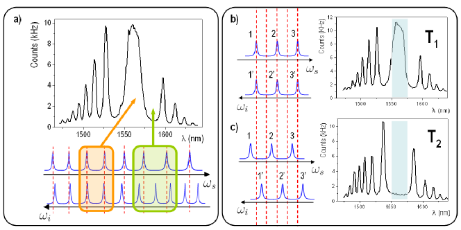
Signal and idler photons can be emitted by the OPO if their frequencies are symmetric with respect to (condition of energy conservation) and also match two distinct modes of the resonator. Emission is thus possible only when the cavity modes for the signal and the idler are symmetric with respect to /2. However, since the spectral range on which the photons can be emitted by SPDC is tens of nanometers wide, it includes thousands of resonant modes. Their relative spacings can vary considerably within this spectral range because of dispersion. Thus, cavity modes for signal and idler photons are symmetric with respect to /2 only in some spectral regions, called clusters [20]. Figure 3 (a) shows this effect for the cluster around 1560 nm. The Giordmaine and Miller diagram ([19, 20]) is also shown. The cavity resonances are plotted for the signal and the idler photon. The signal frequency increases from left to right, while the idler goes in the opposite direction. When the transmitted modes of the resonator for the signal and the idler lie along a vertical line, energy conservation is satisfied and the corresponding pairs of photons can be emitted. This is possible only in some intervals, where a cluster is formed. By changing the temperature of the sample the sequence of the cavity modes moves and the resonance condition is automatically lost for certain clusters of frequencies, but it is obtained for others.
We are interested in the stabilization of the double resonance condition in the region of frequencies around 1560 nm, at which photons are filtered. Figure 3 (b) and (c) show the loss of the double resonance in this spectral region by changing the temperature. In Figure 3(b) a situation of double resonance at a certain temperature is shown: resonant modes for idler and signal lie on the same vertical lines. The corresponding frequency spectrum, displaying a cluster in the region around 1560 nm, is shown on the right. If we change the temperature to (such that T2-T 0.07∘C), the modes move to the left for the signal, and to the right for the idler (Figure 3 (c)). Their superposition on the same vertical lines is lost and double resonance disappears around 1560 nm. If the change of temperature is such that signal and idler modes move by half their FSR (about 0.15 ∘C), the double resonance is restored and we again observe a cluster around 1560 nm. In order to maintain the double resonance at 1560 nm, unlike previous sources, only an accurate control of the temperature is required. A thermal stability of better than is guaranteed by performing a P.I.D. regulation of the temperature using feedback directly from the signal detected by the free-running detector. Since this is a side-of-fringe method, we can not lock on the maximum available signal.
3 Experimental results
3.1 Features of the source
For measuring the coincidences between the photon pairs generated by the source, the free-running detector provides a start signal on the TDC and triggers the other detector, which gives the stop signal. By injecting into the waveguide resonator an effective pump power of 1.6 mW (power effectively coupled in the waveguide), we registered 3400 counts s-1 on the first detector and 5.2 coincidences s-1. From these values we estimate 17 dB of overall losses for the photons directed to the second detector, in other words only 2% of the photons generated inside the resonator reach the second detector. The overall losses for the photons directed to the first detector are a little smaller because of the different insertion losses in the 10-pm filter for the two selected wavelengths. The first source of photons’ losses is inside the waveguide resonator, which we will try to quantify later on. After being emitted, photons undergo 0.4 dB of losses because of the passage through the silicon filter and 5.2 dB for the coupling into the single mode fibre. The internal losses of the 10-pm filter are of 2.8 and 3.8 dB for the photons directed to the first and the second detector respectively. We estimated supplementary losses of 2.4 dB because of how we lock the temperature of the system. By summing all the mentioned values, we have 10.8 and 11.8 dB of losses for the photons directed respectively to the first and the second detector.
Subtracting, for the second photon, the sum of the above mentioned losses (11.8 dB) from the total measured losses (17 dB), we estimate that the losses due to the oscillation of the radiation inside the resonator are 5.2 dB, that is the 30% of the generated photons exit the waveguide resonator. In order to verify this quantity, we computed the probability that a photon, whose frequency matches one resonant mode of the cavity, exits the resonator. By assuming that photons are generated in the middle of the resonator, the probability of exiting after a certain number of round-trips is given by , where represents the absorption losses for a single pass inside the cavity and the reflectivity of the mirrors. Therefore, the probability that each photon exits the cavity can be calculated as:
| (1) |
which gives a value of 0.43 for R=0.85. This calculation takes in consideration only photons in perfect resonance with the cavity, negliging their lorentzian linewidth. This can explain the discrepancy between the calculated value and the one estimated by subtracting the overall losses.
Knowing the detection rates and the total losses in the system we calculate that the source generates 6.6 106 photon pairs per second in the 10-pm window. The photon coherence time is 2.7 ns (as we will see in the next paragraph), so the number of photons per coherence time is 0.02. We keep the pump power low in order to minimize the emission of double pairs [22]. The spectral brightness of the source, calculated considering the overall losses of the system, corresponds to 17 pairs of photons emitted per second, per MHz of bandwidth and per mW of effective pump power (2.2 103 pairs /(s pm mW)) and coupled in a single mode fibre. Therefore, the signal rate of the source is not limited by the pump power, but it is highly affected by the overall losses of the system.
Part of the signal is lost because of the oscillation of the parametric radiation inside the waveguide resonator. These losses are related to the time the photons spend in the resonator before exiting from it. Unfortunately, the resonator bandwidth is related to this time, therefore we cannot reduce the total losses for a constant bandwidth. However, the signal rate can be increased without changing the bandwidth. For example, a single high reflectivity mirror could be used to reduce the signal which exits from the wrong side of the resonator. In this case the reflectivity of the second mirror should be reduced to keep the finesse, and so the bandwidth constant. Otherwise, one can use a smaller resonator. In this way the FSR would be increased and, for keeping the bandwidth constant, the finesse should be increased properly by improving the mirror reflectivities, allowing to exploit the cavity enhancement of the signal [9].
A large part of the signal is also lost in the external optical components. The integrated optics approach could allow to drastically reduce these losses, by integrating filters directly in the waveguide and by fibre butt coupling.
3.2 Detection of high coherence photons
.
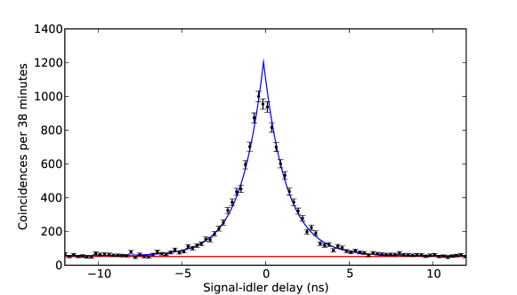
In order to characterize our narrow-band photon pair source, we performed a time correlation measurement with a TDC. For a single-mode doubly resonant OPO the cross correlation function can be expressed, up to multiplicative factors, as [9], where is the time delay between the idler and signal photons and the bandwidth of the down-converted photons. By fitting the coincidences peak, plotted in Figure 4, with the function mentioned above, we obtain MHz. Defining the correlation time between the idler and signal photons as the FWHM of the cross correlation function, that is [9], we find ns. The width of the cross correlation function can also be interpreted in terms of coherence of the down converted photons, which is confirmed by the interference measurement described in the following section. The coherence time is , corresponding to ns. This value is almost an order of magnitude higher than previously reported sources in the telecom regime [17].
The red line in Figure 4 indicates the measured level of the accidental coincidences registered by the TDC, which is in good agreement with the base-line of the fit. This is due to to three main factors. One is the contribution due to the noise of the detectors: accidental coincidences can be registered between the electronic signals corresponding to the dark-counts of the two detectors, between a dark-count of one detector and a real detection on the other detector and viceversa. Accidental coincidences can also arise because of after-pulses in the first detector. Another contribution is due to coincidences between photons of independent pairs. This term is related to the number of double photon pairs per mode that are generated inside the crystal. We measured accidental coincidences of 4.7 Hz ns-1 due to the noise of the detectors, 0.1 Hz ns-1 for after-pulses in the first detector and we estimated 3.4 Hz ns-1 accidental coincidences for independent photon pairs.
3.3 Characterization of energy-time entangled states
Since our source is cw pumped, it generates energy-time entangled photon pairs. Photon pairs may be created at a random time within the coherence time of the pump, but the uncertainty in the difference of the emission times of photons of the same pair is the coherence time of the photons (). In other words, the individual energy values of the down-converted photons are unknown, but their sum is well defined (within the bandwidth of the pump) by energy conservation.
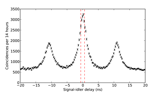
The energy-time entangled states produced by the source can be characterized by performing a Bell-type experiment in the configuration proposed by Franson [16] and measuring the two-photon interference visibility. In our case, instead of sending the two photons to two separated analyzer systems based on equally unbalanced Mach-Zehnder type interferometers, we send them, as shown in Figure 2 (inset b)), to only one interferometer, after which they are filtered and then detected. This scheme corresponds to a folded Franson interferometer [18]. Figure 5 shows the number of coincidences as a function of the signal-idler delay. The three peaks have a temporal separation of approximately 10 ns, as expected from the value of L. The events corresponding to the cases where both the down-converted photons take the short or the long arm of the interferometer give rise to coincidences in the central peak. The indistinguishability of these events provides an interference effect. Side peaks correspond to coincidences between one photon of the pairs which takes the short arm while the other takes the long arm, and viceversa.
By selecting only the coincidences which fall in the temporal interval corresponding to the central peak, as shown in Figure 5 by the dashed red 1.2 ns wide window, and by scanning the temperature of the interferometer, we measure the interference fringes in the coincidence count rate (Figure 6). It is to be noticed that in the folded Franson interferometer, if we change the temperature we vary the sum of the phases of both the photons.
.
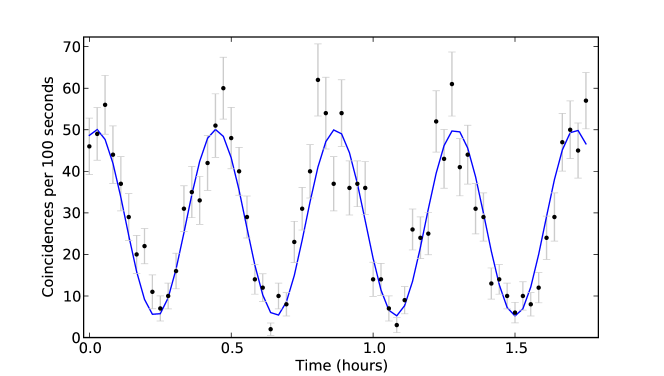
The integration time of each point in Figure 6 is 100 s. The raw fringe visibility is (81.25.5)%, sufficient for violating the limit of given by Bell inequalities. If we subtract the accidental coincidences due to the noise of the detectors we obtain a fringe visibility of (94.45.8)%. These results confirm the good quality of the energy-time entangled states generated by the source.
4 Conclusions
The source of energy-time entangled photon pairs presented in this paper consists of a monolithic doubly resonant OPO system based on a PPLN waveguide resonator that generates photons by SPDC at telecom wavelength with a 117 MHz-bandwidth. We measured a photons’ coherence time of 2.7 ns and a spectral brightness of 17 emitted photon pairs per second, per MHz of bandwidth and per mW of effective pump power (2.2 103 pairs /(s pm mW)) coupled in a single mode fibre. The good quality of the energy-time entangled states we generate is confirmed by the raw visibility of the interference fringes in the coincidence rate after a folded Franson interferometer. The signal rate of the source is highly affected by the overall losses of the system. Losses due to external optical components could be, instead, drastically reduce by integrating filters directly in the waveguide and by fibre butt coupling. Although waveguide-based OPO technology requires further optimization, this source represents the first compact and OPO system at telecom wavelength and a first step towards integrated narrow-band sources of entangled photon pairs.
Acknowledgment
We would like to thank Mikael Afzelius and Hugues de Riedmatten for useful discussions. This work was supported by the EU projects QAP and SINPHONIA and by the Swiss NCCR Quantum Photonics.
References
References
- [1] H. J. Briegel, W. Dür, J. I. Cirac, and P. Zoller. Quantum repeaters: The role of imperfect local operations in quantum communication. Physical Review Letters, 81(26):5932–5935, Dec 1998.
- [2] Christoph Simon, Hugues de Riedmatten, Mikael Afzelius, Nicolas Sangouard, Hugo Zbinden, and Nicolas Gisin. Quantum repeaters with photon pair sources and multimode memories. Physical Review Letters, 98(19):190503+, 2007.
- [3] Hugues de Riedmatten, Mikael Afzelius, Matthias U. Staudt, Christoph Simon, and Nicolas Gisin. A solid-state light-matter interface at the single-photon level. Nature, 456(7223):773–777, December 2008.
- [4] Matthaus Halder, Alexios Beveratos, Nicolas Gisin, Valerio Scarani, Christoph Simon, and Hugo Zbinden. Entangling independent photons by time measurement. Nat Phys, 3(10):692–695, October 2007.
- [5] James K. Thompson, Jonathan Simon, Huanqian Loh, and Vladan Vuletic. A high-brightness source of narrowband, identical-photon pairs. Science, 313(5783):74–77, July 2006.
- [6] Oliver Benson, Charles Santori, Matthew Pelton, and Yoshihisa Yamamoto. Regulated and entangled photons from a single quantum dot. Physical Review Letters, 84(11):2513–2516, Mar 2000.
- [7] R. M. Stevenson, R. J. Young, P. Atkinson, K. Cooper, D. A. Ritchie, and A. J. Shields. A semiconductor source of triggered entangled photon pairs. Nature, 439(7073):179–182, January 2006.
- [8] Z. Y. Ou and Y. J. Lu. Cavity enhanced spontaneous parametric down-conversion for the prolongation of correlation time between conjugate photons. Physical Review Letters, 83(13):2556–2559, Sep 1999.
- [9] Y. J. Lu and Z. Y. Ou. Optical parametric oscillator far below threshold: Experiment versus theory. Physical Review A, 62(3):033804+, Aug 2000.
- [10] Hayato Goto, Yasuo Yanagihara, Haibo Wang, Tomoyuki Horikiri, and Takayoshi Kobayashi. Observation of an oscillatory correlation function of multimode two-photon pairs. Physical Review A, 68(1):015803+, Jul 2003.
- [11] Christopher E. Kuklewicz, Franco N. C. Wong, and Jeffrey H. Shapiro. Time-bin-modulated biphotons from cavity-enhanced down-conversion. Physical Review Letters, 97(22):223601+, 2006.
- [12] J. S. Neergaard-Nielsen, B. M. Nielsen, H. Takahashi, A. I. Vistnes, and E. S. Polzik. High purity bright single photon source. Opt. Express, 15(13):7940–7949, June 2007.
- [13] Xiao H. Bao, Yong Qian, Jian Yang, Han Zhang, Zeng B. Chen, Tao Yang, and Jian W. Pan. Generation of narrow-band polarization-entangled photon pairs for atomic quantum memories. Physical Review Letters, 101(19):190501+, 2008.
- [14] Matthias Scholz, Lars Koch, and Oliver Benson. Statistics of narrow-band single photons for quantum memories generated by ultrabright cavity-enhanced parametric down-conversion. Physical Review Letters, 102(6):063603+, 2009.
- [15] G. Schreiber, D. Hofmann, W. Grundkötter, Y. L. Lee, H. Suche, V. Quiring, R. Ricken, and W. Sohler. Nonlinear integrated optical frequency converters with periodically poledti:linbo3 waveguides. Proceedings SPIE, 4277:144+, 2001.
- [16] J. D. Franson. Bell inequality for position and time. Physical Review Letters, 62(19):2205–2208, May 1989.
- [17] Matthaus Halder, Alexios Beveratos, Robert T. Thew, Corentin Jorel, Hugo Zbinden, and Nicolas Gisin. High coherence photon pair source for quantum communication. New Journal of Physics, 10(2):023027+, February 2008.
- [18] R. T. Thew, S. Tanzilli, W. Tittel, H. Zbinden, and N. Gisin. Experimental investigation of the robustness of partially entangled qubits over 11 km. Physical Review A, 66(6):062304+, Dec 2002.
- [19] J. A. Giordmaine and R. C. Miller. Optical parametric oscillation in linbo_3. In P. L. Kelley, B. Lax, and P. E. Tannenwald, editors, Physics of Quantum Electronics, 1966.
- [20] Robert C. Eckardt, C. D. Nabors, William J. Kozlovsky, and Robert L. Byer. Optical parametric oscillator frequency tuning and control. J. Opt. Soc. Am. B, 8(3):646–667, March 1991.
- [21] A. Henderson. Doubly-resonant optical parametric oscillators: tuning behaviour and stability requirements. Optics Communications, 119(1-2):256–264, August 1995.
- [22] V. Scarani, H. de Riedmatten, I. Marcikic, H. Zbinden, and N. Gisin. Four-photon correction in two-photon bell experiments. The European Physical Journal D - Atomic, Molecular, Optical and Plasma Physics, 32(1):129–138, January 2005.