Alignment of graphene nanoribbons by an electric-field
Abstract
In this paper, we develop an analytical approach to predict the field-induced alignment of cantilevered graphene nanoribbons. This approach is validated through molecular simulations using a constitutive atomic electrostatic model. Our results reveal that graphene’s field-oriented bending angle is roughly proportional to the square of field strength or the graphene length for small deformations, while is roughly independent of graphene width. The effective bending stiffness and the longitudinal polarizability are also found to be approximately proportional to the square of graphene length. Compared with carbon nanotubes, graphene nanoribbons are found to be more mechanically sensitive to an external electric field.
1 Introduction
Graphene’s electronic gap tunable in external electromagnetic fields [1, 2, 3, 4] makes it promising for a number of potential applications in nanoelectronic devices [5, 6, 7]. Since graphene is often supposed to work in a transverse electric field in such devices and its electronic transport properties strongly depend on its atomic structure [8, 9, 10], understanding of graphene’s mechanical behaviors in an electric field is of great importance for nanoelectromechanical systems based on graphene. However, as a novel issue, the mechanical response of graphene to an external field has not yet been reported up to date. How does graphene deform in response to applied electric fields? To answer this question, we developed a simple model to predict the field-induced alignment of cantilevered graphene nanoribbons (GNRs), demonstrating the coupling between the graphene’s field-induced bending, molecular stiffness and electric polarization. This model is validated through molecular simulations, in view of the difficulties of experimental quantification of this electromechanical effects in nanoscale.
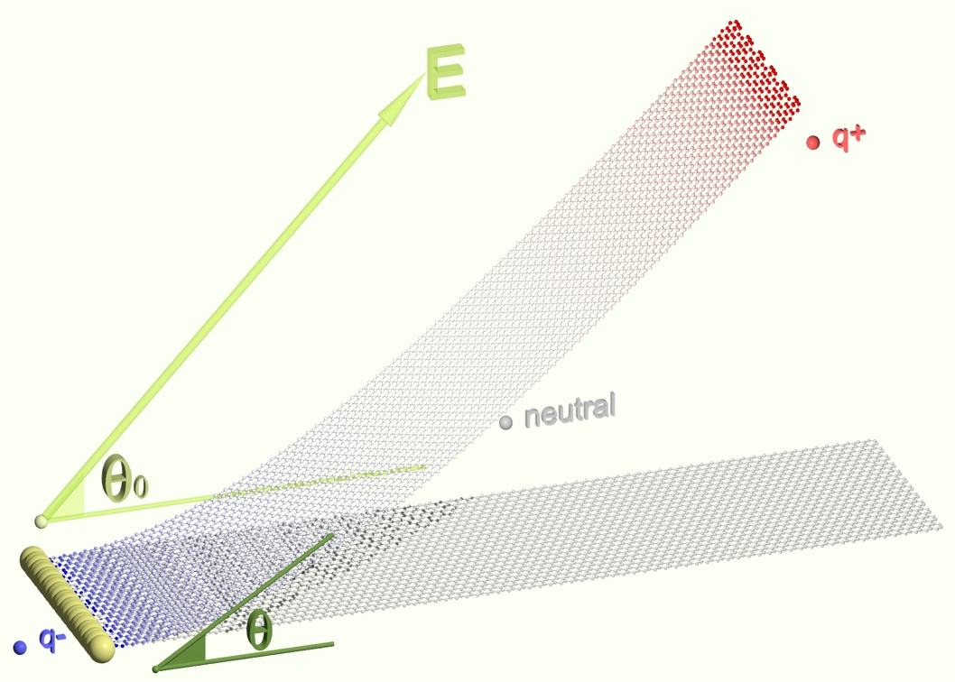
If a thin nanostructure is brought into an electric field, electric polarization effects will induce a moment of force, which tends to orient the nanostructure toward the field direction [11]. This moment will make the nanostructure bent if one end of the nanostructure is fixed on a substrate (see Fig. 1). This alignment has been observed on carbon nanotubes (CNTs) in early experiments [12], and then exploited in designing nanorelays [13] and field emission devices [14]. As can be expected in view of the large similarity in their atomic structures and mechanical properties [15], graphene nanoribbons (GNRs) should exhibit similar mechanical behaviors in an electric field. Furthermore, unlike CNTs, graphene exhibits strong mechanical anisotropy in its transverse direction, with a lateral stiffness about 30 times lower than that in the longitudinal direction [16, 17]. This high lateral structural flexibility makes GNRs ideal field-sensing materials in resonators [5], transistors [18] or sensors [19].
2 Simulations
In this work, molecular simulations were performed to compute equilibrium structures of cantilevered GNRs in an electric field, using an energy optimization method (full details of the simulation techniques can be found elsewhere [20, 21]). The principle of this method is to minimize the potential energy of each atom, which consists of an internal potential due to the C-C chemical bonds and the long-range interaction, and of an external potential induced by applied electrostatic fields. The internal potential is calculated using the adaptive interatomic reactive empirical bond order (AIREBO) potential function [22], which has been used in recent studies on mechanical properties of CNTs [23] and GNRs [24]. The external potential describes the electrostatic interaction between the charges, the dipoles and the external field, it is computed using an atomic charge-dipole interacting model [25, 27, 28], which has been validated through charge-injection experiments using an atomic force microscope [29].
3 Modeling
The main reason of the field-induced alignment of a GNR is the effect of electric polarization, by which a quantity of positive and negative charges are shifted to opposite directions in graphene (see Fig. 1). A moment of a force pair arises from the electrostatic interactions between the field and the induced charges, and makes the graphene bent into the field direction. This field-driving moment highly correlated with the GNR’s polarizability is resisted by the mechanical lateral stiffness of graphene, due to the repulsive interactions between electrons and the rotation of bonds. Considering the correlations between the electric polarizability, the bending stiffness, and the geometry of GNRs, the curvature of a cantilevered GNR in an electric field can be calculated as follows:
| (1) |
where is the bending moment induced by the electric polarization [30], denotes the effective bending stiffness of GNR, stands for the graphene length, is the deflection angle of GNR, , and represent the strength and the direction of the electric field, respectively, and stand for the longitudinal and the transverse molecular polarizabilities of GNR, respectively. is defined as the angle between the initial axis of graphene and the vector from one graphene end to another after deformation. Since the curvature can be approximated as and usually , the governing equation can therefore be written as
| (2) |
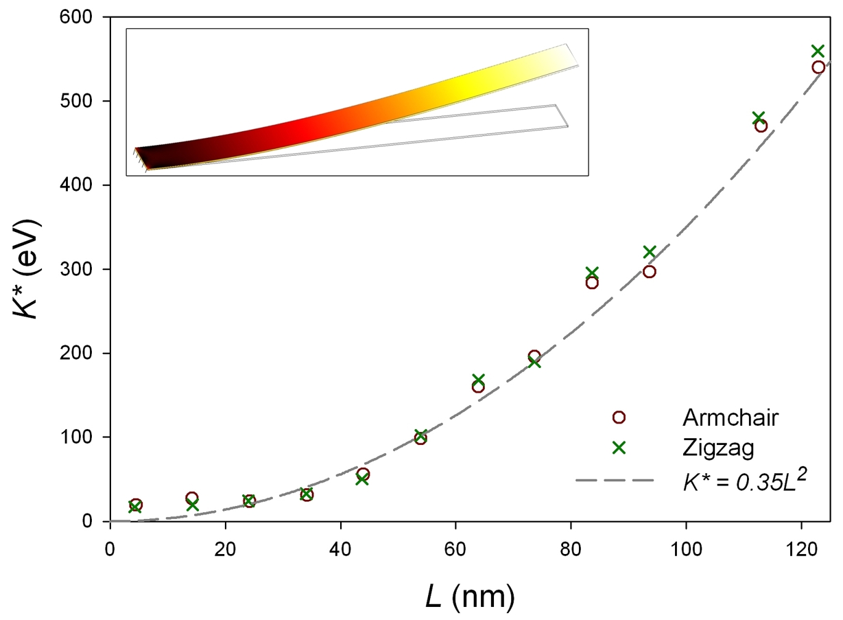
where and stand for the quantities of and per unit width, respectively. In Eq. 2, the parameter representing the mechanical resistance of a GNR is the effective bending stiffness . Here its values were directly computed from atomic simulations by applying a mechanical force at the free end of the GNRs in absence of electric field , instead of using a conventional formula for macroscopic continuous media as the product of the elastic modulus and the area moment of inertia, in order to avoid the problem of definition of the wall-thickness of a one-single-atom thick layer [31]. Note that previous studies showed that the bending stiffness of a CNT is an independent parameter not necessarily related to the representative thickness by the classic formula [32]. Our simulation results show that is about eV when nm and is roughly proportional to when GNRs get longer (see Fig. 2). These simulation data can be fitted using a simple equation as
| (3) |
where eVnm-2 for GNRs with either armchair or zigzag edges. For comparison, we also calculated the effective bending stiffness of CNTs. It is found that the value of of a GNR (nm, eVnm) is about 20 times smaller than that of a (5, 5) CNTs of the same length (eVnm). This large difference in the transverse (lateral) stiffness implies that the alignment of GNRs can be much more significant than that of CNTs for a given magnitude of electric polarization.
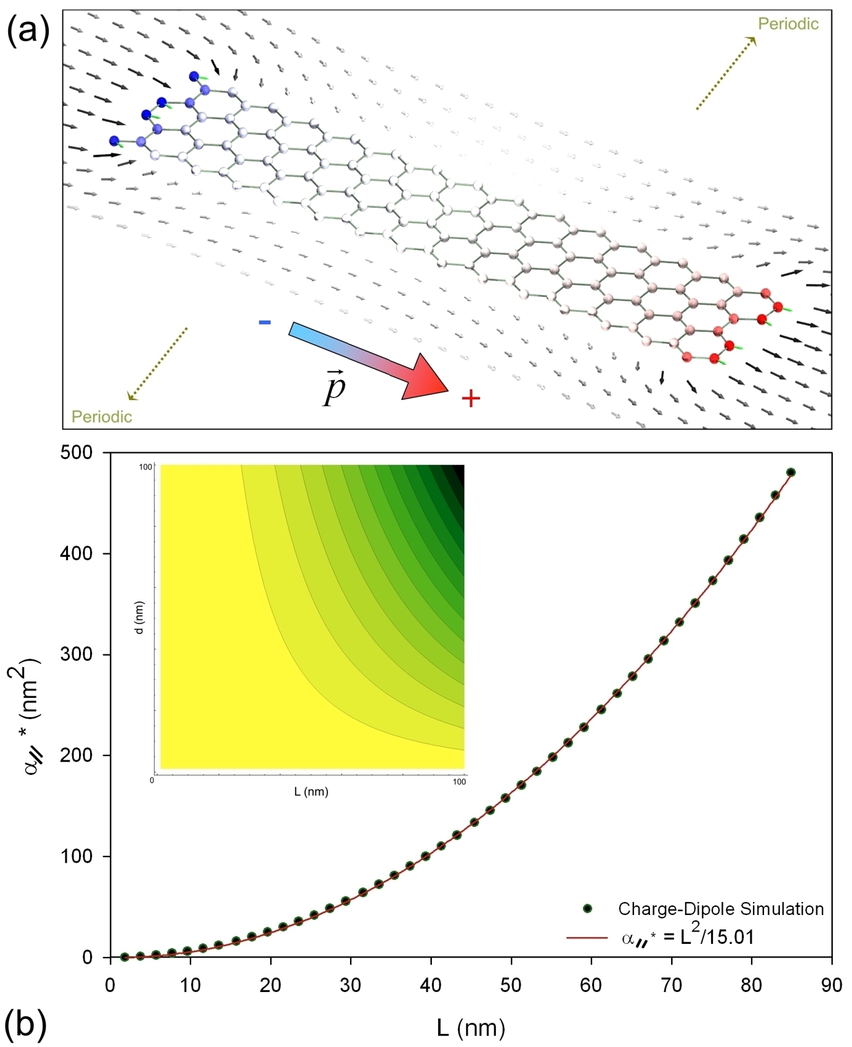
Another important parameter in Eq. 2 is . Its value was determined using electrostatic simulations based on the atomic charge-dipole model [25]. In these simulations, the value of was calculated from the definition , where is the the matrix of molecular polarizability, and stand for the vectors of the induced molecular dipole (see Fig. 3 (a)) and the applied electric field, respectively. As shown in Fig. 3 (b), our simulation results suggest that is roughly proportional to .
| (4) |
where is a constant for either armchair or zigzag GNRs, since no large difference has been found between of these two types of graphene. Since Eq. 4 shows a typical metallic behavior of graphene, we note that of semi-conducting graphene (minimum lateral dimension nm [26]) should hold a linear relationship with . Putting the empirical fits to and into Eq. 2, we finally obtain the governing equation of the electrostatic alignment of GNRs as follows:
| (5) |
where eVnm-2. We note that, since the geometry periodic condition was applied in the width direction in our calculations, we effectively simulated graphene of infinite width. Thus, the edge disorder effects on structural [33] and mechanical properties [24] of graphene were neglected.
4 Results and discussions
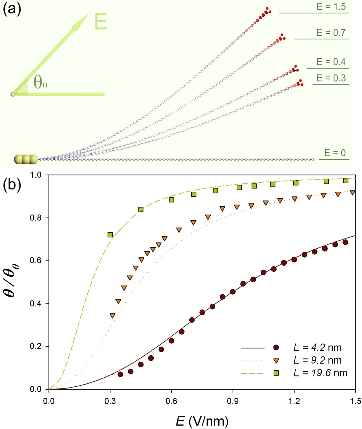
We can see from Eq. 5 that, in small deformation region, is roughly proportional to , or . In Fig. 4, we plot data of the alignment ratio as a function of from molecular simulations in which periodic geometry condition is applied in width direction. A quantitative agreement was obtained between the simulation data and the analytical prediction using Eq. 5. The main inaccuracy can be considered to be contributed from the geometry approximations and the possible slight change of polarizability due to the curvature of graphene. We can see that the S-shaped curve of tends to be flat near the maximal value when the GNRs are well aligned to the field direction. In such a case that , Eq. 5 can be simplified to
| (6) |
for large deformation. Compared with GNRs in same sizes, CNTs were found to be less flexible in an electric field, e.g., a (5,5) SWCNT (nm) can be bent to in an electric field (V/nm and ), while required field strength for producing the same amplitude of alignment for a GNR with the same width and length is about 7 times smaller (V/nm). Analysis on the amplitudes of induced polarization in a GNR and a CNT shows that this difference is mainly due to the fact that the bending stiffness of the GNR is much lower than that of the CNT. Furthermore, we can predict that a multi-layered graphene should be less sensitive to an electric field than a single-layered one is, because of the electric screening effects and the friction between the layers [20].
5 Conclusion
In conclusion, we have developed an analytical model to predict the alignment of cantilevered GNRs to an electrostatic field. Parameters used in this model such as the polarizability and the bending stiffness were determined from numerical fits to the data of simulations using an atomic electrostatic charge-dipole model and an empirical pseudo-chemical potential. This model showed that the alignment angle roughly follows a linear relationship with the square of field strength and the graphene length when the deformation remains small. It was also found that, for GNRs with either armchair or zigzag edges, their effective bending stiffness and longitudinal polarizability are both approximately proportional to the square of graphene length. Comparison showed that a GNR can be more easily oriented to electric fields than a CNT does, due to the GNR’s low transverse bending stiffness.
Acknowledgments
We gratefully thank S. J. Stuart and R. Langlet for help with the numerics. D. Stewart, A. Mayer, M. Devel and W. Ren are acknowledged for fruitful discussions.
References
- [1] Novoselov KS, Geim AK, Morozov SV, Jiang D, Zhang Y, Dubonos SV, et al. Electric field in atomically thin carbon films. Science 2004; 306(5696):666.
- [2] Zhang Y, Tan YW, Stormer HL, Kim P. Experimental observation of the quantum hall effect and berry’s phase in graphene. Nature 2005; 438(7065):201.
- [3] Castro EV, Novoselov KS, Morozov SV, Peres NMR, Dos Santos JMBL, Nilsson J, et al. Biased bilayer graphene: Semiconductor with a gap tunable by the electric field effect. Phys Rev Lett 2007; 99(21):216802.
- [4] Novikov DS. Transverse field effect in graphene ribbons. Phys Rev Lett 2007; 99(5):056802.
- [5] Bunch JS, Van Der Zande AM, Verbridge SS, Frank IW, Tanenbaum DM, Parpia JM, et al. Electromechanical resonators from graphene sheets. Science 2007; 315(5811):490.
- [6] Oostinga JB, Heersche HB, Liu X, Morpurgo AF, Vandersypen LMK. Gate-induced insulating state in bilayer graphene devices. Nature Mater 2008; 7(2):151.
- [7] Son YW, Cohen ML, Louie SG. Energy gaps in graphene nanoribbons. Phys Rev Lett 2006; 97(21):216803.
- [8] Morozov SV, Novoselov KS, Katsnelson MI, Schedin F, Elias DC, Jaszczak JA, et al. Giant intrinsic carrier mobilities in graphene and its bilayer. Phys Rev Lett 2008; 100(1):016602.
- [9] Duplock EJ, Scheffler M, Lindan PJD. Hallmark of perfect graphene. Phys Rev Lett 2004; 92(22):225502.
- [10] Wakabayashi K, Takane Y, Yamamoto M, Sigrist M. Edge effect on electronic transport properties of graphene nanoribbons and presence of perfectly conducting channel. Carbon 2009; 47:124.
- [11] Joselevich E, Lieber CM. Vectorial growth of metallic and semiconducting single-wall carbon nanotubes. Nano Lett 2002; 2:1137.
- [12] Poncharal P, Wang ZL, Ugarte D, de Heer WA. Electrostatic deflections and electromechanical resonances of carbon nanotubes. Science 1999; 283:1513.
- [13] Kinaret JM, Nord T, Viefers S. A carbon-nanotube-based nanorelay. Appl Phys Lett 2003; 82:1287.
- [14] Purcell ST, Vincent P, Journet C, Binh VT. Tuning of nanotube mechanical resonances by electric field pulling. Phys Rev Lett 2002; 89:2761031.
- [15] Lee C, Wei X, Kysar JW, Hone J. Measurement of the elastic properties and intrinsic strength of monolayer graphene. Science 2008; 321(5887):385.
- [16] Bosak A, Krisch M, Mohr M, Maultzsch J, Thomsen C. Elasticity of single-crystalline graphite: Inelastic x-ray scattering study. Phys Rev B 2007; 75(15):153408.
- [17] Lu JP. Elastic properties of carbon nanotubes and nanoropes. Phys Rev Lett 1997; 79(7):1297.
- [18] Meric I, Han MY, Young AF, Ozyilmaz B, Kim P, Shepard KL. Current saturation in zero-bandgap, top-gated graphene field-effect transistors. Nature Nano 2008; 3(11):654.
- [19] Ang PK, Chen W, Wee ATS, Kian PL. Solution-gated epitaxial graphene as ph sensor. J Am Chem Soc 2008; 130(44):14392.
- [20] Wang Z, Devel M. Electrostatic deflections of cantilevered metallic carbon nanotubes via charge-dipole model. Phys Rev B 2007; 76:195434.
- [21] Wang Z, Philippe L. Deformation of doubly-clamped nanotubes in an electrostatic field. Phys Rev Lett 2009; 102:215501.
- [22] Stuart SJ, Tutein AB, Harrison JA. A reactive potential for hydrocarbons with intermolecular interactions. J Chem Phys 2000; 112:6472.
- [23] Ni B, Sinnott SB, Mikulski PT, Harrison JA. Compression of carbon nanotubes filled with C60, CH4, or Ne: Predictions from molecular dynamics simulations. Phys Rev Lett 2002; 88:2055051.
- [24] Shenoy VB, Reddy CD, Ramasubramaniam A, Zhang YW. Edge-stress-induced warping of graphene sheets and nanoribbons. Phys Rev Lett 2008; 101(24):245501.
- [25] Mayer A. Formulation in terms of normalized propagators of a charge-dipole model enabling the calculation of the polarization properties of fullerenes and carbon nanotubes. Phys Rev B 2007; 75:045407.
- [26] Ritter KA, Lyding JW. The influence of edge structure on the electronic properties of graphene quantum dots and nanoribbons. Nature Mater 2008; 8(3):235.
- [27] Wang Z. Effects of substrate and electric fields on charges in carbon nanotubes. Phys Rev B 2009; 79:155407.
- [28] Langlet R, Devel M, Lambin Ph. Computation of the static polarizabilities of multi-wall carbon nanotubes and fullerites using a Gaussian regularized point dipole interaction model. Carbon 2006; 44:2883.
- [29] Wang Z, Zdrojek M, Melin T, Devel M. Electric charge enhancements in carbon nanotubes: Theory and experiments. Phys Rev B 2008; 78:085425.
- [30] Kozinsky B, Marzari N. Static dielectric properties of carbon nanotubes from first principles. Phys Rev Lett 2006; 96:166801.
- [31] Huang Y, Wu J, Hwang KC. Thickness of graphene and single-wall carbon nanotubes. Phys Rev B 2006; 74(24):245413.
- [32] Ru CQ. Effective bending stiffness of carbon nanotubes. Phys Rev B 2000; 62(15):9973.
- [33] Fasolino A, Los JH, Katsnelson MI. Intrinsic ripples in graphene. Nature Mater 2008; 6:858.