Ultranarrow resonance peaks in the transmission and reflection spectra of a photonic crystal cavity with Raman gain
Abstract
The Raman gain of a probe light in a three-state -scheme placed into a defect of a one-dimensional photonic crystal is studied theoretically. We show that there exists a pump intensity range, where the transmission and reflection spectra of the probe field exhibit simultaneously occurring narrow peaks (resonances) whose position is determined by the Raman resonance. Transmission and reflection coefficients can be larger than unity at pump intensities of order tens of W/cm2. When the pump intensity is outside this region, the peak in the transmission spectrum turns into a narrow dip. The nature of narrow resonances is attributed to a drastic dispersion of the nonlinear refractive index in the vicinity of the Raman transition, which leads to a significant reduction of the group velocity of the probe wave.
pacs:
42.50.Gy, 42.55.Sa, 42.65.Dr, 42.70.QsMicro- and nano-defects in photonic crystals (PC) are capable of localizing light within a volume smaller than ( being the wavelength) with a high quality-factor of defect modes (see Bravo-Abad et al. (2007); Lalanne et al. (2008) and references therein). Such structures are often referred to as photonic crystal cavities or micro- and nano-cavities Vahala (2003). They find an important application in many different fields such as photonics McCall et al. (1992), nonlinear optics Bravo-Abad et al. (2007), quantum electrodynamics Vernooy et al. (1998) and others. These structures also underlie the design of low-threshold micro- and nanolasers Englund et al. (2008) and Raman lasers Yang and Wong (2007); McMillan et al. (2006). Inserting a resonant medium (atoms or quantum wells) into a defect results in a significant modification of spectral properties of the PC Ivchenko et al. (1996); Khitrova et al. (1999); John and Florescu (2001). Even more intriguing effects can arise from combining PC properties with the properties of electromagnetically induced transparency (EIT) Soljacic and Joannopoulos (2004). It has been shown recently that in a PC with a defect containing a EIT material Fleischhauer et al. (2005), the defect mode Q-factor for the probe radiation noticeably increases under EIT Soljacic et al. (2005); Arkhipkin and Myslivets (2009), whereas the width of the transmission spectrum narrows. The increase factor can be of order as under EIT it is quite possible that Soljacic et al. (2005) ( is the light velocity in vacuum and is the group velocity of a probe wave in a EIT-medium). A noticeable reduction of the group velocity (slow light) occurs as well under conventional Raman interaction of a probe (Raman) radiation with a strong pump (driving field) Payne and Deng (2001); Inouye et al. (2000); Lee and Lawandy (2001); Sharping et al. (2005), and it occurs with a smaller loss and over a broader spectral range than under EIT Payne and Deng (2001).
In this Letter we suggest a new approach to reduce the width of the transmission (reflection) spectrum of a PC. Our technique is based on the effect of Raman gain Klyshko (1986); Akhmanov and Koroteev (1981) of a probe wave in a defect layer containing a three-level medium (Fig. 1). A probe (Raman) wave with frequency undergoes amplification when interacting with a coherent pump (driving) wave with frequency as the difference between the two frequencies comes close to the Raman transition frequency . The pump intensity is chosen so as to ensure enhancement of the probe wave without however exceeding the stimulated Raman scattering (SRS) threshold. Here, unlike spontaneous Raman scattering, phasing of atomic oscillations occurs throughout the entire volume occupied by light waves, just as it happens under SRS, but without uncontrollable instabilities and with the spectral resolution being determined by the spectral width of applied laser radiation. This scheme is weakly sensitive to pump field intensity fluctuations Akhmanov and Koroteev (1981). We note that Raman gain is being extensively used in high resolution Raman spectroscopy in gases and liquids Akhmanov and Koroteev (1981) as well as in designing high-efficiency continous-wave Raman amplifiers and lasers Repasky et al. (1999); Poelker and Kumar (1992).
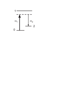
Consider a one-dimensional photonic crystal having a (HL)MHDH(LH)M-type structure. Here and refer to different dielectric layers with a high and low refractive index, and , and thicknesses and , respectively; D is the defect layer with a thickness and the refractive index ; M is the number of periods. The defect layer is filled with three-level atoms. Figure 1 shows the energy level diagram and relevant laser couplings for the present study. The concentration of atoms is such that we can assume that there is no interaction between atoms. Parameters of the PC are chosen to allow excitation of just one defect mode whose spectral width is much larger than that of the allowed transitions and of the Raman transition (in contrast to Yang and Wong (2007); McMillan et al. (2006) and references therein).
Two monochromatic plane waves (the pump and probe) with are normally incident on the PC and propagate along -axis ( at the first layer boundary), which is perpendicular to the PC layers. The frequency difference is close to the Raman transition frequency . The pump field interacts with the transition and the probe field with the adjacent transition . The transition is dipole-forbidden. Only the lower ground state is initially populated. Both waves are assumed to fall within the transmission band of the photonic crystal, i.e. the transition frequency is less than the defect mode width. For simplicity, a unity refractive index is assumed for the medium containing the photonic crystal.
The complex refractive index of the defect layer for a probe field in the presence of a pump wave is given by:
where is the linear nonresonant susceptibility for the probe field; is the complex amplitude of the pump wave; is the concentration of atoms; is the Raman susceptibility Yariv (1975)
Here and are the frequencies of atomic transitions; is the Raman transition halfwidth; is the matrix dipole moment of the transition; is the Plank constant.
The formula for was obtained in the third-order of perturbation theory under the following conditions: and , , and are Rabi frequencies of the pump and the probe wave, respectively, and is the halfwidth of transition. Population of the lower state can be considered unaffected under these conditions. For simplicity, we neglect the Doppler broadenings because the one-photon detuning is sufficiently large and the residual Doppler broadening of Raman transition is small.
Note that in the given approximation, , and the only effect of is to shift the resonant frequency of the defect mode. Therefore the contribution of into the refractive index will be neglected in our further consideration. It is essential that the imaginary part of is negative in the vicinity of the Raman resonance, which implies the probe wave enhancement due to energy transfer from the pump to the probe field. The real part of the refractive index has normal dispersion () Boyd (1992) in this region, therefore the group velocity of the probe wave can be smaller than the light velocity in vacuum Payne and Deng (2001).
In a steady-state approximation, a field in an arbitrary th layer (j = H,L,D) can be treated as a superposition of counter-propagating waves
where and are amplitudes of the forward (incident) and backward (reflected) waves; ; is the refractive index of a -th layer. Note that the refractive index of a defect layer for the probe wave depends on the spatial coordinate since distribution of fields in a defect is non-uniform due to the effect of localization.
Amplitudes and for each layer were found from wave equations by means of recurrent relations Arkhipkin and Myslivets (2009); Balakin et al. (2001) using the continuity of tangential components of the electric and magnetic fields at the interface of adjacent layers. The transmission and reflection spectra were determined as
where and are the input () and output ( is the photonic crystal length) amplitudes of the probe wave, respectively, and is the amplitude of the probe wave reflected from the input face of the photonic crystal.
For the purpose of numerical simulation, we used sodium atomic parameters as a Raman medium. Wavelengths of the probe and the pump fields were chosen to be close to -line and to be 1.8 GHz. The photonic crystal had the following parameters: , , , , . The probe wavelength was chosen so that its frequency under Raman resonance would match the defect mode resonance frequency, the pump detuning being , s-1, , cm-3. For the chosen parameters, calculation of field distribution in the empty defect layer yields a virtually complete spatial overlapping of the pump and the probe field. Intensities of both fields in the defect layer appear to be times as strong as the input ones. Since we assume that in a defect layer , simulation of the transmission and reflection coefficients for the probe field was performed in the undepleted-pump approximation.
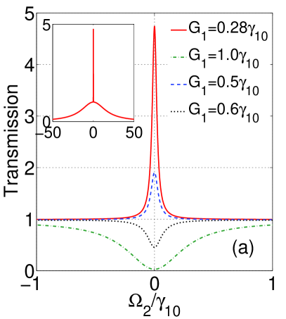
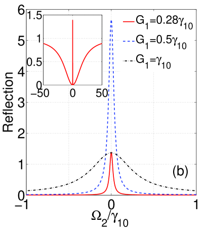
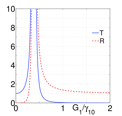
Figure 2a shows typical PC transmission and reflection spectra calculated for the probe wave at different intensities of the driving field. Narrow structures (a peak or a dip) due to the Raman resonance can be observed in the center on the background of a broad transmission band (Fig. 2a). The transmittance can be larger than unity. A narrow peak is also observed in the center of the dip in the reflection spectrum (Fig. 2b) and again the reflectance can be larger than unity. So in a PC with a defect producing the Raman gain, narrow peaks are observed simultaneously in both the transmission and the reflection spectrum. In Fig. 3 transmittance and reflectance maxima are plotted as a function of the Rabi frequency of the driving field. It is seen that the amplitude of the transmission and reflection peaks enhances with the growing pump intensity until the Rabi frequency reaches a threshold, whose value depends on the system parameters. Once this frequency goes beyond the threshold, the amplitude of the transmission peak decreases and the narrow peak is replaced by a dip while the reflectance tends to unity.
A qualitative interpretation of the features of the transmission and reflection spectra of a probe field becomes possible if we look at the problem in terms of a Fabri-Perot cavity (FPC) Lalanne et al. (2008) with the length equal to the thickness of the defect layer , which is filled with a Raman medium. The FPC transmittance for a probe wave ( is the light intensity as it enters FPC and is the transmitted light intensity) can be found from the formula
where and are the transmission and reflection coefficients of mirrors; is the Raman gain factor of the probe wave; is the phase shift after two passes through the cavity; and are effective imaginary and real parts of the refractive index ; is the pump field amplitude in FPC; is the spatial overlapping integral of the pumping wave and the probe field Repasky et al. (1998).
The requirement that determines a resonance frequency of the cavity, for which maximum transmission is observed
| (1) |
For , formula (1) can be rewritten as
| (2) |
From formula (2) it follows that at the transmission coefficient grows with the pump intensity () and can become . In an opposite situation, when , the transmittance decreases as the pump field grows (Fig. 3), and when a dip is formed in the transmission curve. A similar approach can be applied to analyze the reflection coefficient.
The width (at half-maximum) of the narrow transmission peak is given by the expression:
| (3) |
where ; is the resonance frequency of the empty cavity; . A frequency derivative is taken at . For , the formula for turns into a familiar expression for a transmission bandwidth of the empty FPC Yariv (1976). Note that when , the value of equals the group velocity index for a probe wave under Raman interaction Payne and Deng (2001), which can be much larger than unity if dispersion is high (at small width of the Raman transition).
It is seen from (3) that the width of the transmission peak for is a factor of narrower than that of the empty cavity, i.e. there appears a narrow transmission peak. The value of is determined by Raman susceptibility dispersion and depends on the pump intensity. Analysis reveals that the resonance width can be less than the width of the Raman transition . The intensity required for these effects to be observed depends on a number of factors (one-photon pump frequency detuning, Raman resonance width, quality-factor of defect modes) and can be anything from several to hundreds W/cm2 and less.
To summarize the above, we have studied theoretically light propagation through a photonic crystal with a defect, filled with a Raman gain medium and shown that narrow peaks can arise simultaneously in the transmission and reflection spectra of the probe radiation. The position of resonant peaks is determined by the Raman resonance. Transmission and reflection coefficients can be larger than unity. The nature of narrow resonances is attributed to dispersion of the nonlinear refractive index near a Raman transition. Narrow band lasers are required to be able to observe the described effects. We believe that the predicted effects can be also observed in cold atoms, including single atoms, placed into a PC defect, similar to EIT in a cavity Shimizu et al. (2002); Zhang et al. (2008). A combination of the Raman gain effect with the advantages of photonic crystal cavities can be useful for various applications. For example this could help to further reduce the group velocity and obtain longer pulse delays thereby facilitating the designing of Raman lasers of a new generation and atomic clock.
This work was supported in part by the Presidium of the RAS (project no. 27.1), by the Department of Physical Sciences, RAS (project no. 9.1), and also by Federal Task Programm (g/c 02.740.11.0220).
References
- Bravo-Abad et al. (2007) J. Bravo-Abad, A. Rodriguez, P. Bermel, S. G. Johnson, J. D. Joannopoulos, and M. Soljacic, Opt. Express 15, 16161 (2007).
- Lalanne et al. (2008) P. Lalanne, C. Sauvan, and J. Hugonin, Laser and Photonics Review 2, 514 (2008).
- Vahala (2003) K. J. Vahala, Nature 424, 839 (2003).
- McCall et al. (1992) S. L. McCall, A. F. J. Levi, R. E. Slusher, S. J. Pearton, and R. A. Logan, Applied Physics Letters 60, 289 (1992).
- Vernooy et al. (1998) D. W. Vernooy, A. Furusawa, N. P. Georgiades, V. S. Ilchenko, and H. J. Kimble, Phys. Rev. A 57, R2293 (1998).
- Englund et al. (2008) D. Englund, H. Altug, B. Ellis, and J. Vucković, Laser and Photonics Review 2, 264 (2008).
- Yang and Wong (2007) X. Yang and C. W. Wong, Opt. Express 15, 4763 (2007).
- McMillan et al. (2006) J. F. McMillan, X. Yang, N. C. Panoiu, R. M. Osgood, and C. W. Wong, Opt. Lett. 31, 1235 (2006).
- Ivchenko et al. (1996) E. L. Ivchenko, M. A. Kaliteevski, A. V. Kavokin, A. I. Nesvizhskii, and A. F. Ioffe, J. Opt. Soc. Am. B 13, 1061 (1996).
- Khitrova et al. (1999) G. Khitrova, H. M. Gibbs, F. Jahnke, M. Kira, and S. W. Koch, Rev. Mod. Phys. 71, 1591 (1999).
- John and Florescu (2001) S. John and M. Florescu, Journal of Optics A: Pure and Applied Optics 3, S103 (2001).
- Soljacic and Joannopoulos (2004) M. Soljacic and J. D. Joannopoulos, Nat Mater 3, 211 (2004).
- Fleischhauer et al. (2005) M. Fleischhauer, A. Imamoglu, and J. P. Marangos, Rev. Mod. Phys. 77, 633 (2005).
- Soljacic et al. (2005) M. Soljacic, E. Lidorikis, L. V. Hau, and J. D. Joannopoulos, Phys. Rev. E 71, 026602 (2005).
- Arkhipkin and Myslivets (2009) V. G. Arkhipkin and S. A. Myslivets, Quantum Electron 39, 157 (2009).
- Payne and Deng (2001) M. G. Payne and L. Deng, Phys. Rev. A 64, 031802(R) (2001).
- Inouye et al. (2000) S. Inouye, R. F. Löw, S. Gupta, T. Pfau, A. Görlitz, T. L. Gustavson, D. E. Pritchard, and W. Ketterle, Phys. Rev. Lett. 85, 4225 (2000).
- Lee and Lawandy (2001) K. Lee and N. M. Lawandy, Applied Physics Letters 78, 703 (2001).
- Sharping et al. (2005) J. Sharping, Y. Okawachi, and A. Gaeta, Opt. Express 13, 6092 (2005).
- Klyshko (1986) D. Klyshko, Physical basics of quantum electronics [in Russian] (Moscow: Nauka, 1986).
- Akhmanov and Koroteev (1981) S. A. Akhmanov and N. I. Koroteev, Methods of Nonlinear Optics in Light Scattering Spectroscopy [in Russian] (Moscow: Nauka, 1981).
- Repasky et al. (1999) K. S. Repasky, L. Meng, J. K. Brasseur, J. L. Carlsten, and R. C. Swanson, J. Opt. Soc. Am. B 16, 717 (1999).
- Poelker and Kumar (1992) M. Poelker and P. Kumar, Opt. Lett. 17, 399 (1992).
- Yariv (1975) A. Yariv, Quantum Electronics, 2d ed. (New York: Wiley, 1975).
- Boyd (1992) R. Boyd, Nonlinear optics (London: Academic Press, 1992).
- Balakin et al. (2001) A. V. Balakin, V. A. Bushuev, B. I. Mantsyzov, I. A. Ozheredov, E. V. Petrov, A. P. Shkurinov, P. Masselin, and G. Mouret, Phys. Rev. E 63, 046609 (2001).
- Yariv (1976) A. Yariv, Introduction to optical electronics, 2d ed. (New York, 1976).
- Repasky et al. (1998) K. S. Repasky, J. K. Brasseur, L. Meng, and J. L. Carlsten, J. Opt. Soc. Am. B 15, 1667 (1998).
- Shimizu et al. (2002) Y. Shimizu, N. Shiokawa, N. Yamamoto, M. Kozuma, T. Kuga, L. Deng, and E. W. Hagley, Phys. Rev. Lett. 89, 233001 (2002).
- Zhang et al. (2008) J. Zhang, G. Hernandez, and Y. Zhu, Opt. Lett. 33, 46 (2008).