Phase Compensation Enhancement of Photon Pair Entanglement Generated from Biexciton Decays in Quantum Dots
Abstract
Exciton fine-structure splittings within quantum dots introduce phase differences between the two biexciton decay paths that greatly reduce the entanglement of photon pairs generated via biexciton recombination. We analyze this problem in the frequency domain and propose a practicable method to compensate the phase difference by inserting a spatial light modulator, which substantially improves the entanglement of the photon pairs without any loss.
pacs:
03.67.Bg 78.55.Cr 42.50.-pEntangled photon pairs play a crucial role in much of quantum information processing Spe1998 ; A1991 ; C1992 ; C1993 . The most widely used methods for generating entangled photon pairs involve nonlinear optical processes, such as spontaneous parametric down conversion (SPDC) White1998 ; cfli2006 . However, high multi-photon probabilities and low quantum efficiencies associated with SPDC pose serious limitations on their applications in quantum information processing.
As an alternative, biexciton decays in single quantum dots (QDs) have been proposed as good sources of “on-demand” entangled photon pairs Benson2000 . QDs also have the advantages of a mature fabrication technology and ease of integration into larger structures to make monolithic devices. However, “which-path” information provided by the fine-structure splitting (FSS) of the intermediate exciton state destroys the entanglement of photon pairs Santori2002 . To overcome this problem, the energy splitting is tuned to near zero either by rapid thermal annealing Young2005 , or optionally applying in-plane electric fields Electric2007 , magnetic fields Magnetic2006 ; Young2006Na , uniaxial stresses Stress2006 or light fields Light2009 . Such “triggered” entangled photon pair sources can also be engineered by simply selecting appropriate QDs with small FSSs Hafenbrak2007 , by energy-resolved post-selection Petroff2006 , and by using highly-symmetric, site-controlled quantum dots grown in inverted pyramids Mohan2010 .
In considering the photon emission distribution in the time domain, the two-photon state created in a QD is Young2007
| (1) |
where denotes the FSS energy, is the time delay between the first (biexciton) and the second (exciton) photon emission events, is the exciton photon emission probability distribution, and is the exciton lifetime. Thus time integration will reduce the overall degree of entanglement, and even lead to classically correlated states Young2008 .
In this Report, we analyze this problem in the frequency domain and propose an optical arrangement to compensate the phase difference. Given the maximally entangled state , the fidelity is greatly improved and in our method is accompanied without photon losses, thus surpassing previous schemes that apply timing gates Young2008 and employ energy-resolved post selection Petroff2006 .
By Fourier Transformation, we can re-express the two-photon state in the frequency domain
| (2) |
with
The polarization density matrix is given by
| (7) |
with and is the phase difference. The fidelity with Bell state is
| (8) |
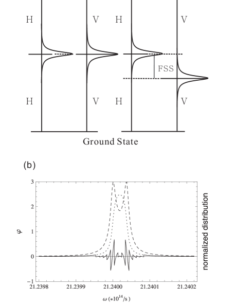
FSS limits the degree of entanglement in two ways, as illustrated in Figure 1. First, the phase difference between H- and V-polarized photons reduces the fidelity after time integration. Second, the overlap between their photon frequency distributions decreases as the FSS energy increases. We concentrate first on the phase difference.
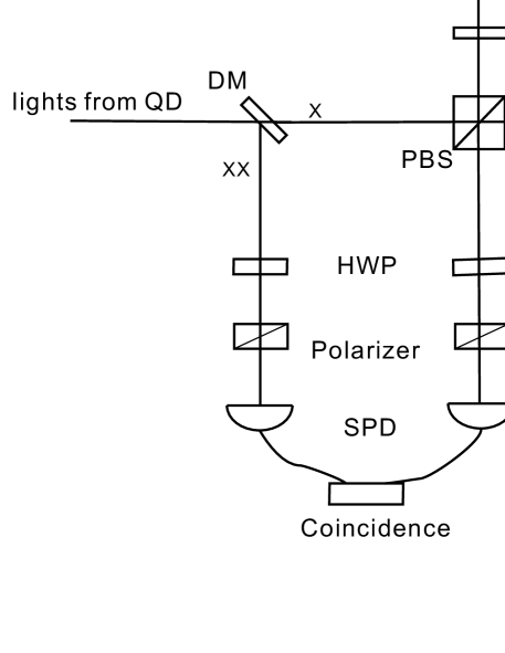
Phase compensation is generally difficult to realize in the time domain, because it requires an accurate phase delay () rapidly varying with time. As shown in Fig. 1(b), the phase distribution is clearly a non-monotonic function of frequency, so it is also impossible to realize this compensation by simply using a dispersive element. The proposed experimental setup is shown in Fig. 2. The light from the QDs should initially be collimated and focused. For widely-used self-assembled QDs, the separation between biexciton (XX) and exciton (X) emission lines is generally several meV because of the biexciton binding energy Michio2006 , that then enables the use of a dichroic mirror (DM) to separate them. The emitted XX photon goes directly to a single photon detector (SPD). The X photon enters a polarization beam splitter (PBS), which reflects the V polarization and transmits the H polarization. The two parallel gratings distribute the photons in a spatial mode depending on their wavelengths. The diffraction angle is determined by , where is the incident angle and is the photon’s wavelength. The last mirror reflects the photon back. The quarter-wave plate (QWP) is placed. Passing through the QWP twice changes H (V) polarization to V (H) polarization. The half-wave plate (HWP) and the polarizer placed before the detectors are used to choose the polarization state for coincidence detection. All gratings, incident angles, and optical paths are identical in both arms of H and V polarization. As shown in Fig. 1(b), the phase difference is driven close to zero after which is divided in many small steps. Here each step corresponds to an angular frequency bandwidth of . Some parameters have been chosen, the vertical distance between the two parallel gratings is 0.29 meters, the gratings’ constant m, and the incident angles satisfy = 0.18. The angular frequency , corresponds to a wavelength of 0.887 m. We choose the length of each step in front of the mirror as m, which is much larger than the photon wavelengths.
Based on equation (4), the variation fidelity with FSS energy is shown in Fig. 3, where the dotted line corresponds to the phase difference as mentioned above, and produces exactly the same results as obtained in the time domain Young2007 . The solid line corresponds to the ideal case without phase difference (i.e, ). Here the QD exciton lifetime is set to 0.77 ns which is consistent with experimental observations Young2007 .
Several methods can be used to realize this sectionalized compensation spatially, such as an optical coating with varying thickness, a medium of varying refractive index, or Fiber Bragg Grating (FBG) which is the standard dispersion compensation techniques used in optical fiber communications K1994 . However the more appropriate method would be to use a phase-only spatial light modulator (SLM), which can change the phase delay distribution spatially pixel by pixel with an electric signal. This is important in this scheme as different QDs have different FSS energies, and hence their phase distributions differ. The advantages is that while other methods may require completely new fabrication to adapt to certain QDs, here with a SLM, different QDs just require changes in the electric signal for each pixel of the SLM. The phase range shown in Fig. 1(b) can never be larger than , therefore the phase compensation can be easily realized with a SLM. Moreover, SLMs with pixel resolution of 20 m are commercially available, and even 5 m resolution can be achieved. A higher resolution will give finer compensations, and thus obtain the fidelity closer to the ideal altough at the expense of photon loss due to diffraction. With 20 m length steps, corresponding to the bandwidth , the result is already very close to the ideal case as shown in Fig. 3. The dashed line gives the result after phase compensation and the solid line shows the ideal case when . Furthermore, for , diffraction effects are negligible. The photon loss caused by diffraction can be estimated as , which is vanishingly small in this case.

As shown in Fig. 3, with a FSS energy of 2.5 eV, the fidelity increases from 0.553 to 0.764 after phase compensation. Even with of 3.8 ev, the fidelity is still over 0.7 after phase compensation. We have noted that in a published report that with of 2.5 eV obtained by applying a timing gate, the fidelity increases from 0.46 with a gate width of 2 ns to 0.73 with a gate width of 49 ps Young2008 . A simple calculation gives a theoretical collective efficiency of 0.925 with the 2 ns gate, but rapidly declines down to 0.061 with the 49 ps gate. It is obvious that to get higher fidelity more photons have to be rejected by the timing gate. In contrast, we improve the fidelity by a factor of 0.21 without any photon loss theoretically. Considering the practical performance of the gratings (efficiency 90%) and the SLM (efficiency 95% ), we estimate the experimental efficiency of 62% in performing phase compensation. The bare postselection in energy Petroff2006 is even more wasteful than applying a timing gate Young2008 , since one has there to select a small fraction of photons with overlapping frequencies, and further ensure that the phase difference does not change much in the selected frequency band.
Even after phase compensation, the fidelity unfortunately cannot attain unity, because it is limited by the photons outside the overlapping part of the frequency. Further improvements in fidelity can be achieved by rejecting these photons. For example, an even better performance than that of the ideal case shown with solid line in Fig. 3, can be achieved in cooperation energy-resolved postselection as reported in Ref. Petroff2006 . With phase compensation, this postselection can be more efficient and result in a much enhanced performance in fidelity. To illustrate the point, let S=2 eV, if the angular frequency bandwidth is set at , then after phase compensation, the fidelity increases from 0.578 to 0.9 with a theoretical efficiency of 0.2 (still much higher than that obtained by applying a timing gate). Our result means that if a relative low efficiency can be tolerated, even a non-zero FSS is acceptable and required no magnetic or other fields to tune the FSS to zero, thus greatly simplifying the experimental setup. As reported previously CFLi2008 , calculations reveal that InAs/InP QDs offer smaller FSSs with only a little flux around zero for individual QDs. Very recently, Mohan et al. Mohan2010 reported that highly symmetric, site-controlled quantum dots show FSS energies of several eV. Utilizing these types of QDs, our scheme may lead to a practical entangled photon pairs source that is efficient and easy to control.
Another advantage of this setup is that it is easy to control the output phase, an aspect that is highly desirable in a multitude of contexts in quantum information processings. This is achieved simply by either allowing the SLM to introduce a constant delay, or changing the optical path in one of the arms.
It should be noticed that we have not considered the effect of spin flipping and background light here, which in practice may slightly degrade the experimental results. Further studies would need to include the evolution of these effects and others, and try to solve them in the frequency domain.
To summarize, we have analyzed the degradation in entanglement of photon pairs emitted from QDs with non-zero FSS, and proposed a phase compensation scheme with the insertion of a SLM to greatly enhance entanglement gaining theoretical efficiencies approaching 100%. An even better performance in fidelity can be achieved in cooperation with frequency post-selection.
This work was supported by National Fundamental Research Program, National Natural Science Foundation of China (Grant No. 60621064, 10874162, and 10734060).
References
- (1) Special issue of Proc. R. Soc. London A 454, No.2921 (1998).
- (2) A. K. Ekert, Phys. Rev. Lett. 67, 661 (1991).
- (3) C. H. Bennett, and S. J. Wiesner, Phys. Rev. Lett. 69, 2881 (1992).
- (4) C. H. Bennett, G. Brassard, C. Crépeau, R. Jozsa, A. Peres, and William K. Wootters, Phys. Rev. Lett. 70, 1895 (1993). D. Boschi, S. Branca, F. De Martini, L. Hardy, and S. Popescu, Phys. Rev. Lett. 80, 1121 (1998).
- (5) Andrew G. White, Daniel F. V. James, Philippe H. Eberhard, and Paul G. Kwiat, Phys. Rev. Lett. 83, 3103 (1999).
- (6) Jin-Shi Xu, Chuan-Feng Li, and Guang-Can Guo, Phys. Rev. A 74, 052311 (2006).
- (7) Oliver Benson, Charles Santori, Matthew Pelton, and Yoshihisa Yamamoto, Phys. Rev. Lett. 84, 2513 (2000).
- (8) Charles Santori, David Fattal, Matthew Pelton, Glenn S. Solomon, and Yoshihisa Yamamoto, Phys. Rev. B. 66, 045308 (2002).
- (9) R. J. Young, R. M. Stevenson, A. J. Shields, P. Atkinson, K. Cooper, D. A. Ritchie, K. M. Groom, A. I. Tartakovskii, and M. S. Skolnick, Phys. Rev. B. 72, 113305 (2005).
- (10) B.D. Gerardot, S. Seidl, P.A. Daigarno, R. J. Warburton, D. Granados, J.M. Garcia, K. Kowalik, and O. Krebs, Appl. Phys. Lett, 90, 041101 (2007).
- (11) R. M. Stevenson, R. J. Young, P. See, D. G. Gevaux, K. Cooper, P. Atkinson, I. Farrer, D. A. Ritchie, and A. J. Shiedlds, Phys. Rev. B. 73, 033306 (2006).
- (12) R. M. Stevenson, R. J. Young, P. Atkinson, K. Cooper, D. A. Ritchie, and A. J. Shiedlds, Nature 439, 12 (2006).
- (13) S. Seidl, M. kroner, A. Högele, K. Karrai, R. J. Warbuton, A. Badolato, and P. M. Petroff, Appl. Rhys. Lett. 88, 203113 (2006).
- (14) Andreas Muller, Wei Fang, John Lawall, and G. S. Solomon, Phys. Rev. Lett. 103, 217402 (2009).
- (15) R. Hafenbrak, S. M. Ulrich, P Michler, L Wang, A Rastelli and O. G. Schmidt, New J. Physics. 9,315 (2007).
- (16) N. Akopian, N. H. Lindner, E Poem, Y. Berlatzky, J. Avron, D. Gershoni, B. D. Gerardot and P. M. Petroff, Phys. Rev. Lett. 96, 130501 (2006).
- (17) A. Mohan, M. Felici, P. Gallo, B. Dwir, A. Rudra, J. Faist, and E. Kapon, Nature Photonics (7 March 2010) doi:10.1038/nphoton.2010.2 Letter
- (18) A. J. Hudson, R. M. Stevenson, A. J. Bennett, R. J. Young, C. A. Nicoll, P. Atkinson, K. Cooper, D. A. Ritchie, and A. J. Shields, Phys. Rev. Lett. 99, 266802 (2007).
- (19) R. M. Stevenson, A. J. Hudson, A. J. Bennett, R. J. Young, C. A. Nicoll, D. A. Ritchie, and A. J. Shields, Phys. Rev. Lett. 101, 170501 (2008).
- (20) Michio Ikezawa, Selvakumar V. Nair, Hong-Wen Ren, Yasuaki Masumoto, and Harry Ruda, Phys. Rev. B 73, 125321 (2006).
- (21) K. O. Hill, F. Bilodeau, B. Malo, T. Kitagawa, S. Thériault, D. C. Johnson, and J. Albert, Opt. Lett. 19, 1314 (1994).
- (22) Lixin He, Ming Gong, Chuan-Feng Li, Guang-Can Guo, and Alex Zunger, Phys. Rev. Lett. 101, 157405 (2008).