Computational study of microwave oscillations in absence of external field in nonstandard spin valves in the diffusive transport limit
Abstract
An anomalous (inverse) spin accumulation in the nonmagnetic spacer may build up when the spin valve consists of magnetic films having different spin asymmetries. This leads to wavy-like dependence of spin-transfer torque on the angle between magnetizations, as predicted by spin-dependent diffusive transport model, and also confirmed experimentally. Making use of these predictions, we have numerically studied the magnetization dynamics in presence of such a wavy torque in Co(8 nm)/Cu(10 nm)/Py(8 nm) nanopillar, considering geometry with extended and etched layer. In both cases we specify conditions for the out-of-plane precession to appear in absence of external magnetic field and neglecting thermal fluctuations. We prove the assumption of wavy-like torque angular dependence to be fully consistent with experimental observations. We also show that some features reported experimentally, like nonlinear slope of frequency vs. current behavior, are beyond the applicability range of macrospin approximation and can be explained only by means of full micromagnetic analysis.
pacs:
67.30.hj,75.60.Jk,75.70.Cn,78.20.BhI Introduction
The concept of spin transfer was introduced in pioneering works by SlonczewskiSlonczewski1996:JMMM and BergerBerger1996:PRB . They have shown that spin polarized current can exert torque on a thin magnetic film due to transfer of spin angular momentum, influencing the magnetic state of the layer. The spin-transfer torque (STT) originates from spin asymmetries of the two independent transport channels, and its well known manifestation is current induced magnetic switching (CIMS)AlHajDarwish:PRL ; Tsoi2004:PRB as well as generation of microwave oscillationsSlavin:PRB ; Kiselev2003:Nature . Properties of STT are related to the sample design and material parameters. This also implies that CIMS and current-perpendicular-to-plane giant magnetoresistance (CPP-GMR) phenomena are correlatedGmitra2009:PRB and depend on the same structural parameters. By considering two well-defined conduction spin-channels, Valet and FertValet:PRB incorporated most of these parameters into CPP-GMR model based on spin diffusion transport equations. Generalization of Valet-Fert approachBarnas2005:PRB includes STT and provides an unified description of STT and CPP-GMR in the diffusive transport limit. For symmetric spin valves, with fixed and free layer made of the same material, such as Co/Cu/Co, this model predicts standard behavior of STT, which does not vary qualitatively from Slonczewski’s result obtained in the ballistic transport limitSlonczewski1996:JMMM . In this case, current of one orientation drives switching to antiparallel configuration while opposite current stabilizes parallel stateKatine:PRL . In presence of applied fields higher than the coercive field, the generation of microwave oscillations is possibleKiselev2003:Nature . Similar behavior has been recently observed also in Py/Cu/Py (Py = Permalloy), both experimentallyKrivorotovScience:Science ; KrivorotovPRB2008:PRB and theoretically KrivorotovPRB2007:PRB . Moreover, standard STT associated precession was also reported at high perpendicular magnetic field in an asymmetric spin valveKiselev2004:PRL , where the magnetic layers are made of different materials (Co(40 nm)/Cu(10 nm)/Py(3 nm)).
However in such asymmetric structures, provided that spin asymmetries and spin diffusion lengths differ markedly and the thickness obeys certain conditions, qualitatively different situation may arise. The STT vanishes and changes sign in a certain noncollinear magnetic configuration (wavy-like STT) due to the appearance of an inverse spin accumulation in the nonmagnetic spacer. Therefore, current flowing in one direction destabilizes both collinear magnetic configurations, whereas the opposite current stabilizes both of them. The first case is of particular interest as it leads to excitation of stationary oscillation modes in absence of external magnetic field.
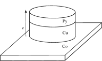
In this paper we present a systematic study of dynamic response of a magnetic film to such wavy-like STT. The asymmetric pillar under study is a spin valve consisting of a fixed layer, nonmagnetic spacer and a free magnetic layer, Co(8 nm)/Cu(10 nm)/Py(8 nm) respectively, with the elliptical cross-section of . The polarization of the fixed layer is assumed to be along the ellipse major axis. Recently, such asymmetric structures have been investigated theoreticallyBarnas2005:PRB ; Gmitra2006:APL ; Gmitra2007:PRL as well as experimentally at low and zero applied fieldsBoulle2007:NP ; Boulle2008:PRB . To authors’ best knowledge, no micromagnetic analysis of such structures in the diffusive transport limit has been performed so far. Moreover, the reported macrospin (referred to in the following also as single domain) study does not describe correctly the dynamics at low applied magnetic fieldsBoulle2008:PRB . Here, starting with the single domain approximation, and extending study to the full micromagnetic model, we explain the origin of out-of-plane precession (OPP). In particular, we show that only full micromagnetic model can successfully reproduce magnetization dynamics at low applied magnetic field.
The paper is organized as follows. Section II describes briefly the torque calculations in the diffusive transport limit. The methodology of simulations is presented in section III. The results of numerical study and their discussion are to be found in section IV, whereas final conclusions in section V.
II Spin torque in an asymmetric pillar
As mentioned in the introduction, structure of a pillar determines the dependence of STT on the angle between magnetization vectors. Generally, STT consists of two components, , where is the in-plane (IP) component, while is the out-of-plane (OP) one. These two components can be written asBarnas2005:PRB
| (1a) | ||||
| (1b) | ||||
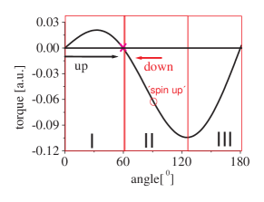
where denotes the normalized (unit) vector along the magnetization of the free layer, is the normalized magnetization of the fixed layer, and is the current density. The prefactors and are independent of current , but they generally depend on the angle between and . These parameters have been computed from the diffusive transport modelBarnas2005:PRB . First, from the boundary conditions for spin current and spin accumulationBrataas:EPJ we calculate the spin current. The torque is then calculated from the normal component of the spin current in the nonmagnetic film at the interface with the magnetic layer. Most of the parameters used in this description, like interface and bulk spin asymmetry coefficients, interface resistances, layer resistivitiesBassJMMM:JMMM , and spin diffusion lengthsBassJPCM:JPCM are provided by the corresponding CPP-GMR experiments. The two remaining parameters, i.e. the real and imaginary part of the mixing conductanceBrataas2006:PR have been extracted from spin current interface transmission calculationsStiles:JAP . The variation of normalized (to ) STT with the angle for symmetric and asymmetric spin valve is shown in Fig. 1.
In the system under considerations (Fig. 1), the OP torque is roughly 2 orders of magnitude smaller than the IP component, which means that the latter will not markedly influence the magnetization dynamics. Comparing the angular dependence for the standard (Fig. 1a) pillar structure with that for the nonstandard one (Fig. 1b), the uniqueness of the latter is clearly visible – at some critical angle the IP component of the torque vanishes. This gives rise to interesting dynamics at zero and low magnetic fields. Above certain threshold current both collinear states of the magnetization are unstable for one current orientation, and the only solution of the Landau-Lifshitz-Gilbert (LLG) equation is then the steady state precession or a noncollinear static magnetization stateBarnas2006:MSEB .


III Simulation methodology
Magnetic dynamics of the free layer is described by the Landau-Lifshitz-Gilbert (LLG) equation with the STT included. This equation, when written as the equation for time evolution of the unit vector , takes the form
| (2) |
where , , is the effective field normalized to the saturation magnetization of the free layer, is the damping constant, is the thickness of the free layer, and with being the gyromagnetic ratio and standing for the magnetic vacuum permeability. Since is a small parameter, in numerical simulations we assumed and .
In our convention the current flowing from the fixed towards the thin (free) layer defines the positive current direction, . Note, that in this convention the positive current triggers switching to the antiparallel configuration, whereas negative current stabilizes parallel alignment in standard spin valves. On the other hand, negative current in nonstandard spin valves supports oscillatory regime, while positive current stabilizes both collinear configurations.
Only the dynamics of the free layer is resolved, while magnetization of the fixed layer is assumed to remain uniform in the film plane. Apart for this, we have neglected all thermal effects. In the macrospin analysis, the effective field is assumed to include the self-magnetostatic termAharoni:JAP , the uniaxial anisotropy field, and the external magnetic field. The uniform magnetostatic coupling field (with the fixed layer) can also be taken into account. In the micromagnetic study, on the other hand, the magnetic field is modified with respect to macrospin case. First, the self-magnetostatic term is computed using the Fast Fourier Transform technique assuming that the magnetization is uniform in each computational cellNewell:JGR . Second, six-neighbor dot product representation is used to compute the exchange field. Unless stated differently in the text, the following values of the relevant parameters have been chosen for the systematic study: the anisotropy constant , exchange constant , damping constant , , and . As follows from this choice for permalloy, the corresponding exchange length equals , and therefore we choose discretization mesh. Further refinement of the cell size in the -direction does not lead to any substantial difference in system frequency response. Fourth-order Runge-Kutta scheme was employed for the time integration of Eq. III, and the stability analysis was carried out for the chosen mesh to assign appropriate time integration step.
IV Results and discussion
Before comparing results obtained from macrospin approximation with those from full micromagnetic study, one should consider that the concept of single domain magnetic particle in many situations is not justified. We shall explain how the difference between the results of macrospin and micromagnetic analysis arises from the appearance of an inhomogeneous magnetization and a finite exchange field. The exchange energy density of a closed configuration increases as the particle size decreases, and this could, in principle, justify macrospin approach below certain critical size of the system, even though spin torque makes the estimation of this critical size difficultBerkovJMMM:JMMM . However, as reported in [BerkovPRB71:PRB, ], steady state precession of a thin square nanoelement exhibits complicated transition from quasi-macrospin to chaotic behavior already at the size of 30 nm, which invalidates single domain approximation for most of experimentally studied systems. Moreover, on the basis of micromagnetic analysis Berkov and GornBerkovPRB72:PRB identified some artifacts of macrospin model in the ballistic transport limit. These artifacts might cause misleading interpretation of the origin of some observed phenomenaKiselev2003:Nature . Aware of that, we cannot however deny that macrospin dynamics is very rich and in many cases can serve as a tool for the basic understanding of physics behind.
Since the precessional states appear for negative current (according to the definition introduced in section III), we limit the following considerations to negative current. For sake of simplicity, the current denotes the absolute value of the negative current.
IV.1 Extended geometry
We start our numerical study with a pillar structure having an extended fixed layer, like the one shown schematically in Fig. 2a. In this case, the influence of interlayer magnetostatic coupling field (ICF) can be neglected. Since the anisotropy of Py is also small, one concludes that it is mainly the self-magnetostatic field that drives the system dynamics. In the following we consider the role of initial magnetic state of the system, and begin with the parallel magnetic configuration.

IV.1.1 Initial P state
Assume the system is initially in the parallel configuration and increase the current step-like (with the step ) in order to identify possible oscillatory regimes. As the initial state for simulation at a given current we assume the state the systems arrived at in the preceding step of simulations, i.e. for current . Simulation results from both macrospin approximation and micromagnetic model reveal that an in-plane precession (IPP) is supported at zero applied field, which is consistent with previous study [Gmitra2006:APL, ; Gmitra2007:PRL, ]. The associated frequency redshift with current is a well known phenomenon and is attributed to the increase of the oscillation amplitude. Interestingly the redshift in the micromagnetic model turns out to be much slower than in the macrospin approximation, which is opposite to the results obtained in the ballistic transport limitBerkovJMMM:JMMM . We shall explain this effect later on.
As follows from Fig. 3, the precessional states in the macrospin model disappear above a certain ’cut-off’ current (I=35 mA), where a stable static ’spin-up’ (normal to the film plane) magnetization state is formed. Existence of this static state has been recently reported in [Gmitra2006:APL, ; Balaz2009:PRB, ; Balaz2008:APP, ], where it was found that the LLG equation has just two possible solutions – self-sustained precession or a stable static state (above the ’cut-off’ current). The appearance of the latter can be explained with the help of Fig. 4. As the current is applied and the system is initially in the P state, the STT counterbalances the damping, and steady state is obtained in region I. When the current is increased, the oscillation amplitude increases and therefore the critical angle (marked as cross), at which the torque vanishes, is reached. The magnetization starts then aligning along the effective magnetic field, and finally the stable ’spin-up’ state is reached. No such static state has been reported in micromagnetic simulations. Assume now that the system in macrospin simulations is in the static ’spin-up’ state and then the current is decreased (region II). The self-magnetostatic field in the static point together with the STT may trigger the OPP in some current range, as shown in Ref. [Gmitra2007:PRL, ]. Again, no OPP appears in the micromagnetic simulations. In general, when the angle between magnetizations of the free and fixed layer is lower than the critical angle (region I), only IPP is observed. As the critical angle is crossed (region II) the OPP can be triggered in the macrospin model, as shown in Refs. [Jaromirska:tbp, ; Gmitra2006:APL, ]. However, we point again that the ’spin-up’ state is not reached in micromagnetic simulations because of the inhomogeneous character of the magnetization. Therefore, even though single domain model predicts OPP, which was also reported experimentallyBoulle2008:PRB , the interpretation of its origin requires further considerations.
IV.1.2 Initial AP state
As we have seen above, two factors play crucial role in the excitation of precessional states in the system. These are the magnetization state which imposes the initial self-magnetostatic field, and the initial angle between the magnetic layers, which determines the initial torque sign and strength. The IPP is supported in region I (Fig. 4), whereas in region II the static state has been found in the macrospin approximation so far.
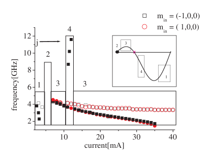
In order to investigate modes supported in region III, we assume AP configuration as the initial state. As the current is increased, micromagnetic simulations give a fast red-shifting branch corresponding to (precession around the axis) – marked as 1 in Fig. 5 (open squares). Fast amplitude increase with increasing current soon leads to switching towards the P state and damped oscillations stabilizing P state are observed (range 2). However, as certain threshold current is reached (P is now the initial state), the STT (region I) counterbalances the damping and the second red-shifting branch, , is observed (range 3). Micromagnetically, the only difference between starting with initial P or AP state (open circles and open squares respectively) is the appearance of first fast red-shifting branch.
Analogous comparison (see full circles for initial P state and full squares for initial AP states, Fig. 5) in the macrospin approximation leads to similar conclusions, but now an additional mode is visible. When current is high enough and assuming the AP state as the simulation is initialized, the system might be forced to move into region II leading to the appearance of OPP marked as 4 (full squares). Earlier in this section it was shown that after crossing from region I through the critical angle into region II, the static state was observed. Here, however, dynamics in region II is forced by the initial configuration and therefore the OPP can be observed. In other words, in the single domain approximation the region I supports , region II supports static state or OPP (depending on the preceeding configuration), whereas in region III the mode can be observed. This result is consistent with the one reported in [Gmitra2006:APL, ].
IV.2 Etched geometry
In the extended structures (Fig. 2a) as discussed above, the interlayer coupling field (ICF) could be neglected, and the initial self-magnetostatic field together with the STT determined the induced dynamics (region I, II or III). However in the etched geometry, schematically shown in Fig. 2b, the ICF can no longer be neglected. We have calculated this field micromagnetically, and by neglecting large OP edge values we have estimated -36mT IP as an average ICF. This is a significant contribution and therefore dynamics different from that obtained for extended structures is expected.
IV.2.1 Initial P state
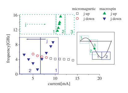
The dynamical response reveals now some new interesting features. The macrospin approximation with the initial P state leads to the steady OPP, which appears at 10.4 mA when the current is increased, as indicated in Fig. 6 (corresponding range for observed mode marked with dotted lines). As the threshold current for OPP is reached, the blue-shifting branch appears in range 2. This OPP is not preceded by any IPP oscillations – range 1, because the additional contribution from ICF places the system directly in region II. As the frequency of OPP oscillations increases with increasing current, the corresponding amplitude decreases and the angle between the magnetic moments of both layers approaches the critical angle. When this angle is reached, the static state discussed in the preceding subsection is observed (point 3). Now we start to decrease current. The system is initially in the static point and dynamic range is marked with solid lines in Fig. 6. The OPP appears then in the range 1, and the amplitude and increase as the current decreases. The torque minimum is then passed and the system moves to the region III, which results in mode in range 2, where the amplitude decrease (with decreasing current) results effectively in the frequency redshift with current. The asymmetry in the macrospin frequency response to increasing and decreasing current is clearly a consequence of the torque asymmetry, the existence of a critical angle, and irreversibility of the transition from region I to region II.
Dynamics in the micromagnetic model is simpler. Due to the effect of ICF, the system directly switches to the region III, and only one red-shifting branch is observed. This mode is qualitatively equivalent to the macrospin one in range 2 observed for decreasing current.
IV.2.2 Initial AP state
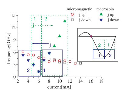
As discussed above, starting from the initial P state introduced in the macrospin approximation hysteretic dependence in frequency vs. current response. Clearly it is due to the asymmetric shape of the torque angular dependence. This effect, however, disappears when the initial state is AP. When the current is increased (dotted in Fig. 7), the system is directly placed in region III supporting red-shifting branch () in range 1 (inset Fig. 7). As the amplitude increases with increasing current, transition to range 2, where OPP oscillations are triggered, is observed. In the torque diagram this is equivalent to the transition from region III over the torque minimum to region II. Since the critical angle is not crossed, this transition stays reversible and no hysteretic behavior in the frequency response is observed.
As before, micromagnetically no OPP was found. This indicates that the system supports stable oscillations only in region III.
IV.3 Influence of the exchange field
IV.3.1 The extended geometry
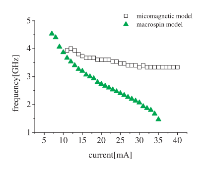
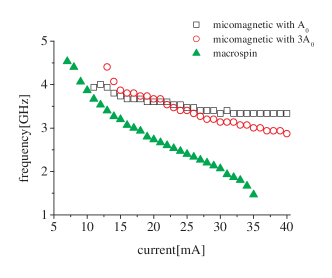
An open question is why the OPP modes obtained in the macrospin model and also reported experimentallyBoulle2008:PRB , have not been found in micromagnetic simulations. As has been shown, to observe the OPP-associated blueshift, one has to force the system dynamics in region II. Moreover, we have learnt that the appearance of the macrospin ’spin-up’ state was a consequence of system crossing over the critical angle. This has not been reached micromagnetically due to the inhomogenous nature of the magnetization (finite exchange field) in the model. Therefore, one should expect that the appearance of OPP in micromagentic model is hindered by the underestimated exchange field, and that increase of the exchange constant should lead to a convergence of both models. Using the bulk exchange constant for thin films might cause a great underestimation of exchange fields in these structures. Larger values of exchange constants, as compared to the standard bulk ones, have been reported in Py dotsLai:JMMM and thin films Scholl:PRB . Therefore, we have investigated magnetization dynamics in the extended geometry for the following values of the exchange constant: , , , , . The frequency-current behavior with is compared to the results of macrospin model in Fig. 8. Clearly increasing the exchange constant changes the slope of micromagnetic frequency redshift towards macrospin results. We conclude that the finite exchange energy favoring inhomogenous magnetization state causes this slope difference retarding the dynamics.
IV.3.2 Etched geometry
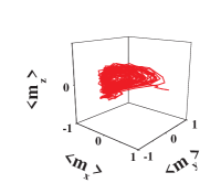
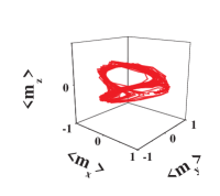
So far in this geometry (ICF included) we have found that as the current was increased micromagnetically induced dynamics in region III imposed frequency redshift and the macrospin dynamics in region II supported OPP-associated blueshift. Still we want to check whether micromagnetic dynamics can be shifted to region II by increasing the exchange constant. The micromagnetic temporal evolution of the averaged magnetization component at I=13 mA for and results in different orbits, Fig. 9a and Fig. 9b, respectively. Clearly in the first case the ICF places the system in region III forcing dynamics. However, as the exchange field is increased, which favors uniform magnetization, an open clamshell orbit is formed (Fig. 9b) shifting the dynamics towards the border between region III and II. One should note that the cross-over between the regions is impossible in this geometry since the ICF has a significant contribution to the effective field and hinders the appearance of OPP.
IV.4 Comparison to experimental data

Still no OPP (supported in the dynamic region II) has been predicted micromagnetically, although such modes were reported experimentallyBoulle2008:PRB in extended structure. However previous paragraphs have given some important clues. We have learnt about the importance of the underestimation of the exchange field. Therefore, we assume for further study. Secondly, as the magnetization always stays inhomogeneous to some extend, the toruqe calculated locally (cell by cell) inherits this inhomogeneity and we shall scale the torque strength by a factor of 0.5 to counterbalance this effect. Thirdly, micromagnetically the transition from dynamic region I to II was impossible. Thus in order to observe OPP one has to force dynamics in region II by forcing the transition from region III to II (i.e. imposing AP initial state). As presented in Fig. 10, indeed under all above mentioned assumptions both models converge. Micromagnetic dynamics is forced first in region III supporting , then switching towards P state takes place (range of current where no sustained oscillations are observed, as discussed before), and then branch (region I) is triggered. At a certain threshold, however, the dynamics in region II supporting blueshift can be obtained. The threshold of this OPP coincides with the experimental one from [Boulle2008:PRB, ]. The magnitude of the frequency jump associated with the transition IPP-OPP in the macrospin approximation does not fit to the experimental values, and micromagnetic approach proves to be more accurate. The fact that experimentally OPP was reported by starting from P state (opposite to our results) means that transition between region I and II prohibited micromagnetically is experimentally possible due to thermal activation. As our simulations neglect the effect of thermal fluctuations, the dynamic region II can be only reached by transition from region III.
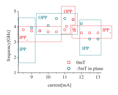
One should note that not all regimes (dynamics in all regions I, II, III) predicted by the simulations for the extended geometry were observed experimentally. Low angle IPP does not provide enough output power to be measured via GMR effect. Therefore in order to conduct meaningful comparison we have concentrated on the OPP regime (region II), which was both predicted numerically and observed experimentally. In the absence of external field satisfactory qualitative agreement has been reached (Fig. 11, compare to Fig. 6a in Ref. [Boulle2008:PRB, ]). Not only the threshold current ( mA compared to mA) but also the agility (0.6 GHz/mA and 0.7 GHz/mA respectively) are in good agreement. The remaining quantitative difference in frequency values is a consequence of uncertain estimation of the factors entering micromagnetic model, like saturation magnetization and/or damping. Moreover, the dynamics at -5mT IP field reveals that OPP threshold current is smaller with respect to 0mT case, which is again consistent with the experimental results. Interestingly, both approximately linear at 0mT and nonlinear at -5mT behavior of the frequency as a function of current, are well reproduced in frames of micromagnetic model. Note that this feature was not reported in single domain model. Furthermore, micromagnetic model predicts experimentally observed saturation at -5mT, i.e. in a certain current range the frequency stays relatively constant. In the model it is associated with the large angle orbit stabilization around the torque minimum, i.e. the system approaches the border of dynamic regions II and III, and the torque shape becomes flat around its minimum. Furthermore, current increase leads to transition between OPP (region II) and (region III) and reappearance of the clamshell orbit. However, since neither was the IPP reported in the experiment prior to the appearance of OPP, as predicted micromagnetically, nor it could have been detected following OPP regime (because of low output power) so obviously the experimental cut off current refers to the threshold current for IPP reappearance in the model. Note that micromagnetically the main mode (supported over largest range of currents) in case of 0mT was the , whereas even low applied field of -5mT IP forced the dynamics in region III and therefore the was observed as the main mode. In other words in the absence of external field the increased exchange constant enabled direct dynamics in region II (and associated linear frequency vs. current slope) and additional field forced the transition from region III to region II resulting in the appearance of the saturation regime. Clearly the OPP in both cases is preceded by different dynamics.
V Conclusions
The results emerging from the macrospin and micromagnetic model very often do not converge. Lack of this convergence is attributed to a couple of factors. It was shown that the discrepancies arise from the inhomogenous magnetization state and finite exchange field. We concluded that the OPP in the macrospin model might appear as a consequence of the ’spin-up’ static state state, which seems to be characteristic of the macrospin model. On the other hand, the absence of OPP in the micromagnetic model was identified as a combined consequence of the underestimation of the exchange constant and the role of the initial self-magnetostatic field. By setting the initial state and the exchange constant favoring the appearance of the OPP, a good qualitative agreement was reached between the predictions of both models. Thus, only micromagnetic model has proven to predict correctly dynamics reported experimentally.
Acknowledgment
This work was supported by EU Training Network SPINSWITCH (MRTN-CT-2006-035327). JB also acknowledges support by funds from the Ministry of Science and Higher Education as a research project in years 2006-2009 within the EUROCORES Programme FoNE (project SPINTRA).
References
- (1) J.C. Slonczewski. J. Magn. Magn. Mater., 159, 1996.
- (2) L. Berger. Phys. Rev. B, 54, 9353, 1996.
- (3) M. AlHajDarwish; H. Kurt; S. Urazhdin. Phys. Rev. Lett., 93, 157203, 2004.
- (4) M. Tsoi; J.Z. Sun; M.J. Rooks. Phys. Rev. B., 69, 100406, 2004.
- (5) A.N. Slavin; V.S. Tiberkevich. Phys. Rev. B, 72, 094428, 2005.
- (6) S.I. Kiselev; J.C. Sankey; I.N. Krivorotov; N.C. Emley; R.J. Schoelekopf; R.A. Buhrman. Nature, 425, 2003.
- (7) M. Gmitra; J. Barnaś. Phys. Rev. B, 79, 012403, 2009.
- (8) T. Valet; A. Fert. Phys. Rev. B, 48, 10, 1993.
- (9) J. Barnaś; A. Fert; M. Gmitra; I. Weymann; V. Dugaev. Phys. Rev. B, 72, 024426, 2005.
- (10) J.A. Katine; F.J. Albert; R.A. Buhrman; E.B. Myers; D.C. Ralph. Phys. Rev. Lett., 84, 3149, 2000.
- (11) I.N. Krivorotov; N.C. Emley; J.C. Sankey; S.I. Kiselev; D.C. Ralph; R.A. Buhrman. Science, 307, 2005.
- (12) I.N. Krivorotov; N.C. Emley; R.A. Buhrman; D.C. Ralph. Phys. Rev. B, 77, 054440, 2008.
- (13) I.N. Krivorotov; D.V. Berkov; N.L. Gorn; N.C. Emley; J.C. Sankey; S.I. Kiselev; D.C. Ralph; R.A. Buhrman. Phys. Rev. B, 76, 024418, 2007.
- (14) S.I. Kiselev; J.C. Sankey; I.N. Krivorotov; N.C. Emley; M. Rinkoski; C. Perez; R.A. Buhrman; D.C. Ralph. Phys. Rev. Lett., 93, 3, 2004.
- (15) M. Gmitra und J. Barnaś. App. Phys. Lett., 89, 223121, 2006.
- (16) M. Gmitra und J. Barnaś. Phys. Rev. Lett., 99, 097205, 2007.
- (17) O. Boulle; V. Cros; J. Grollier; L.G. Pereira; C. Deranlot; F. Petroff; G. Faini; J. Barnaś; A. Fert. Nature Phys., 3, 2007.
- (18) O. Boulle; V. Cros; J. Grollier; L.G. Pereira; C. Deranlot; F. Petroff; G. Faini; J. Barnaś; A. Fert. Phys. Rev. B, 77, 174403, 2008.
- (19) A. Brataas; Yu. V. Nazarov; G.E.W. Bauer. Eur. Phys. J. B, 22, 99, 2001.
- (20) J. Bass; W.P. Jr. Pratt. J. Magn. Magn. Mat, 200, 274, 1999.
- (21) J. Bass; W.P. Jr. Pratt. J. Phys. Cond. Mat., 19, 183201, 2007.
- (22) A. Brataas; G.E.W. Bauer; P.J. Kelly. Phys. Rep., 427, 2006.
- (23) M.D. Stiles; A. Zangwill. J. App. Phys, 91, 6812, 2002.
- (24) J. Barnaś; A. Fert; M. Gmitra; I. Weymann; V. Dugaev. Mat. Sci. Eng. B, 126, 2006.
- (25) A. Aharoni. J. App. Phys., 1998.
- (26) A.J. Newell; W. Williams; D.J. Dunlop. J. Geophys. Res., 1993.
- (27) D.V. Berkov; J. Miltat. J. Magn. Magn. Mat., 320, 7, 2008.
- (28) D.V. Berkov; N.L. Gorn. Phys. Rev. B, 71, 052403, 2005.
- (29) D.V. Berkov; N.L. Gorn. Phys. Rev. B, 72, 094401, 2005.
- (30) P. Baláž; M. Gmitra; J. Barnaś. Phys. Rev. B, 79, 144301, 2009.
- (31) P. Baláž; M. Gmitra; J. Barnaś. Acta Phys. Pol., 115, 2008.
- (32) E. Jaromirska, P. Baláž, L. López Díaz und J. Barnaś. to be published.
- (33) M.F. Lai; Z.H. Wei; Ch.R. Chang; N.A. Usov; J.C. Wu; J.Y. Lai. J. Magn. Magn. Mat., 282, 2004.
- (34) D. Scholl; M. Donath; D. Mauri; E. Kay. Phys. Rev. B, 43, 16, 1991.