A Xenon Condenser with a Remote Liquid Storage Vessel
Abstract
We describe the design and operation of a system for xenon liquefaction in which the condenser is separated from the liquid storage vessel. The condenser is cooled by a pulse tube cryocooler, while the vessel is cooled only by the liquid xenon itself. This arrangement facilitates liquid particle detector research by allowing easy access to the upper and lower flanges of the vessel. We find that an external xenon gas pump is useful for increasing the rate at which cooling power is delivered to the vessel, and we present measurements of the power and efficiency of the apparatus.
keywords:
Xenon , Condenser , Recirculation pump1 Introduction
Particle detectors based on condensed noble gases have found wide application in high energy physics, astro-particle physics, and nuclear physics. Noble liquids are attractive candidates for particle detectors due to their ease of purification, good charge transport properties, high scintillation efficiency, and in the case of xenon, high density and short radiation length. Examples of recent rare-event searches based on cryogenic noble gases include CLEAN/DEAP [1], XMASS [2], ZEPLIN [3], XENON [4], LUX [5], WARP [6], ArDM [7], EXO [8], ICARUS [9], and MEG [10].
The experimental methods of liquid noble gas detectors have been developed in small prototype instruments whose liquid volumes range from a few cubic centimeters to tens of liters. In these prototypes, the system is typically cooled either by liquid nitrogen or by directly coupling the storage vessel to the cold head of a refrigerator. These techniques have several attractive features, including simplicity, robustness, and the availability of great cooling power. However, both of these cooling strategies typically require a significant amount of space above or below the storage vessel be devoted to the cryogenics. In contrast, room temperature detector technologies, such as gas proportional counters or plastic scintillator, are not burdened by a cryogenic system, which is particularly advantageous for prototyping work where the freedom to make maximal use of the space around the detector provides valuable flexibility.
In this article we describe a system for condensing and storing a noble gas (xenon) where the cooling system is spatially separate from the liquid storage vessel, leaving only the cryostat in the space surrounding the vessel. This configuration facilitates many common laboratory operations, particularly those which require access to the upper or lower flanges of the storage vessel. Examples include the installation of detector structures and the insertion and removal of material samples and radioactive sources. This setup also provides direct optical access to the interior of the vessel for viewing or for laser injection, and it simplifies the construction of a lead shield.
Our primary motivation for pursuing the remote cooling method discussed here is to allow the space above the liquid xenon vessel to be used for ion tagging and retrieval experiments in the context of the EXO double beta decay search. EXO has proposed to eliminate radioactive backgrounds by identifying the barium ion produced in the double beta decay of 136Xe [11]. The identification method may require that a device be inserted into the active volume of the double beta decay detector to retrieve the final state nucleus. The condenser and liquid xenon vessel described in this article will allow both a barium ion calibration source and an insertion and retrieval device to be coupled to the xenon vessel from above.
In the last decade pulse tube cryocoolers have attracted attention as convenient and reliable means to liquefy noble gases. For example, technology has been developed for the MEG and XENON experiments using a modified cryocooler integrated into a liquid xenon storage vessel [12]. Several other recent articles have reported on the development of a small-scale helium condenser based on a pulse tube cryocooler where the condenser is located directly in the neck of a liquid helium storage dewar [13][14][15]. In our system, we also employ a pulse tube cryocooler, and our condenser is conceptually similar to the helium condenser described in references [13]-[15], although in our case the remote storage vessel represents an additional complication. Note that we report here the results of cooling and liquefaction tests carried out with xenon. Similar results could likely be obtained with other heavy noble gases having lower saturation temperature, such as argon or krypton, provided that the heat leaks in the system are minimized.
2 Apparatus
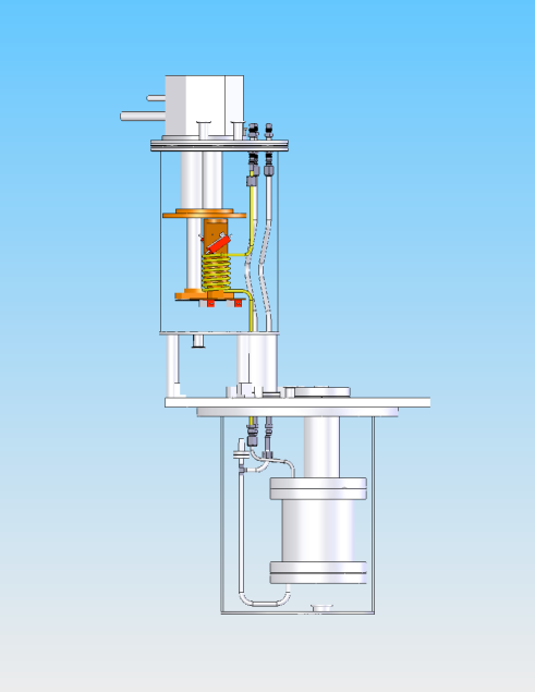
The system consists of two units: a helical copper condenser and a stainless steel liquid xenon (LXe) storage vessel. A system drawing and plumbing schematic are shown in Figures 1 and 2, respectively. The condenser is located above the vessel, and condensed liquid flows downward through a 1/4” stainless steel (SS) tube to the top of the vessel. The condenser is cooled by the cold head of a cryocooler, while the vessel is cooled only by the xenon. The entire system is enclosed in a vacuum-insulated cryostat composed of two SS cylinders connected by a bellows. The two cylinders and bellows form one vacuum volume for pump-out purposes. The radiative heat leak is reduced by wrapping the system components in super-insulation consisting of 10-15 alternating layers of aluminized mylar and fabric.

2.1 Condenser and Temperature Control
The condenser is a helical coil of 1/4” diameter Oxygen Free High Conductivity copper (OFHC) tube, which was chosen for its purity and thermal conductivity. The tubing is partially annealed; non-annealed tube was found to kink when coiled. The coil is brazed to a 2” diameter cylindrical shank of OFHC copper, which is mechanically attached to the coldhead of a pulse tube cryocooler [16]. The total length of the cooled portion of the tube is 30 inches (five turns).

As shown in Figure 3, the cold head has two stages, with base temperatures of 22 K and 8 K for the first and second stages, respectively. These base temperatures are far below what is required to liquefy xenon (triple point of 161 K), but should allow the system to condense the lighter noble gases. To ensure temperature uniformity in the condenser, and to achieve good thermal control, each end of the condenser is coupled to one of the two stages of the cold head. We refer to the upper half of the condenser (coupled to the first stage of the cold head) as the “pre-cooler”, and the lower half (second stage) as the “post-cooler”. The function of the pre-cooler is to cool the room temperature xenon gas to the saturation temperature, while the function of the post-cooler is to remove the latent heat of vaporization, thereby effecting the phase change.
The pre-cooler and the post-cooler are independently temperature controlled by trim heaters. The heaters are driven by a common 77 W regulated DC power supply, and each heater circuit is controlled by a PID temperature feedback unit [17]. The controllers adjust the current in each heater via the gate voltage on two power FETs.
The pre-cooler trim heaters are mounted on flats in the cylindrical shank of the condenser. These flats make a narrow “neck” between the coil and the upper cold stage, thus reducing the cooling power and allowing for more precise temperature control. A stainless steel shim between the condenser shank and the cold head further reduces the cooling power of the pre-cooler, which was found to be excessive for our purposes. The post-cooler trim heaters are attached to a plate on the bottom of the shank, which is itself attached to the second stage of the cold head via a flexible copper braid. The braid was chosen to provide a flexible thermal bridge so that the condenser is mechanically constrained at its upper end only. The control temperatures for the two PID feedback loops are measured by thermocouples located on the neck and on the plate for the pre-cooler and post-cooler, respectively.
In typical operation, the pre-cooler set point temperature is chosen to be 179.5 K, and the post-cooler temperature is chosen to be a few degrees cooler. In practice, however, the post-cooler temperature tends to stabilize around 193 K during condensation, and thus the post-cooler heater does not power on.222Nevertheless, the post-cooler was found to be crucial for maintaining a uniform temperature throughout the condenser; see Section 6. This reflects the fact that the thermal coupling between the post-cooler and the second stage of the cold head has too much thermal resistance. It is likely that this resistance limits the power and efficiency of the condenser, so we intend to modify this arrangement in the near future. Currently, the condensation that does occur is sufficient for our purposes.
The trim heaters on the pre-cooler allow the condenser to adjust for the effects of changes in the gas flow rate. At high flow rates, significant heat is delivered to the condenser by incoming room temperature xenon gas, so the pre-cooler trim heater reduces its power output to maintain the set point temperature. In some cases, the incoming heat was found to be sufficient to warm the condenser to one or two degrees above the PID set point. At zero flow or low flow rates, the heat delivered to the condenser by the gas is small, and the pre-cooler trim heater provides compensation to keep the condenser temperature above the freezing point of xenon. Consequently, one benefit of the pre-cooler PID feedback loop is that it prevents over-cooling in the event that a large gas flow suddenly stops.
We present some measurements of the cooling power of the second stage of the PT805 near LXe temperature. (Cryomech, the cryocooler manufacturer, does not report this data at such high temperatures.) We attached a known thermal resistance to the second stage of the cold head, applied heat from the opposite end, and measured the temperature at each end. Once thermal equilibrium is reached, the cooling power is equal to the power delivered by the heater, and can also be inferred from the temperature gradient across the known thermal resistance. These two methods give results in agreement with each other. We find that the cooling power is 25 W at 65 K, 26.2 W at 75 K, and 32.2 W at 152 K.
2.2 Xenon Vessel
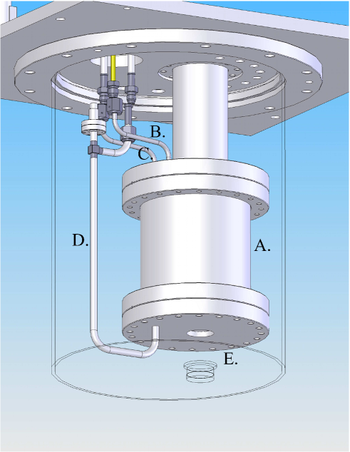
The xenon vessel, seen in Figure 4, is a 6” x 6” OD cylinder constructed from stainless steel, which was chosen for its purity and thermal mass. This volume is sufficient to hold 10 kg, or about 3 liters, of LXe, as well as a particle detector. The top and bottom of the vessel are 8” Conflat flanges. The vessel is suspended from a vertical 3” OD stainless steel tube, 6” in length, which penetrates its top flange. At its upper end, the 3” tube is welded to a 4 5/8” Conflat flange and a large stainless steel plate which provides mechanical support. The plate also acts as part of the cryostat. The 4 5/8” flange and tube allows direct access to the interior of the xenon vessel from the laboratory. With a glass viewport attached to this flange, the LXe can be seen inside the vessel. This access port can also be used to introduce detectors, materials, or radioactive sources. A smaller, fused-silica viewport is welded into the bottom of the vessel; it is paired with an identical viewport in the cryostat to admit laser light for use in LXe purity tests.
The vessel has three plumbing connections for xenon flow: a 1/4” SS liquid supply line that enters the vessel at the top, a 3/8” liquid return line that drains the vessel from the bottom, and a 1/4” gas return line that exits the vessel at the top; see Figures 2 and 4. LXe from the condenser runs down the liquid supply line and collects in the bottom of the vessel and in the liquid return line. A heater on the liquid return line is used to boil the liquid for re-circulation or for recovery. The gas return line at the top of the vessel allows gas to circulate freely through the vessel, especially when the vessel is filled with liquid. As discussed in Section 3 below, free recirculation of gas is important for system operation. All three plumbing lines have VCR fittings so they can be disconnected from the rest of the system, thus allowing the condenser to be removed for servicing.
2.3 Recirculation Pump
An external, custom gas recirculation pump is used to force xenon flow through the condenser and the xenon vessel. It can achieve controllable xenon flow rates of up to 10 SLPM. The pump is a bellows-type, made entirely of stainless steel, except for a teflon sleeve. The pump is driven by a 1/3-HP, three-phase motor [18]; the motor itself is controlled by an inverter [19], which allows flow control via adjustment of the repetition rate of the pump.
2.4 Level Meter
A capacitive level sensor is integrated into the liquid return line. It has a co-axial cylindrical geometry formed by suspending an 11.5” x 1/4” OD stainless steel tube inside the 3/8” OD liquid return line. The inner conductor is vented to allow the liquid to flow unimpeded. It is wrapped at the top and bottom with a small amount of Kapton tape to prevent electrical shorting. The sensor has a capacitance of 104 3 pF in vacuum (224 3 pF including cabling ). Because the level meter is in the liquid return line, rather than the vessel itself, it will only accurately read the liquid level in the vessel when the pressures are equal. This can be ensured by keeping the gas return valve in Figure 2 open.
Changes in capacitance are measured with a custom circuit. The level sensor is in series with a resistor, forming a low-pass RC filter. An AC voltage of amplitude 0.15 V and frequency 8 kHz is input to the filter, and the voltage across the capacitor is amplified and rectified for computer readout by a data acquisition board [20]. To maximize sensitivity and dynamic range, the resistor in the filter was chosen such that 8 kHz is near the knee frequency.
The response of the circuit output was calibrated with a set of known capacitances. A quadratic fit of this data is used to interpolate for future measurements. The capacitance can then be converted to a liquid level measurement based on the known dielectric constant of LXe. Changes in capacitance as small as 1 pF can be measured, corresponding to a height sensitivity of about 1 mm.
2.5 Alarm system
We have constructed an alarm system to notify lab personnel in the event of a serious system failure, such as a power outage. Three alarm conditions are considered: loss of electrical power to the cryocooler, loss of electrical power to the trim heater power supply and/or PID controllers, and an overpressure alarm. Each alarm is represented by a switch which closes if the alarm condition is present. The switch then activates a commerical pager unit [21], which dials a list of phone numbers until the alarm is acknowledged. The pager unit derives power from a UPS to ensure that it remains active in the event that electrical power is lost throughout the lab. Test alarms can be generated with a push button to confirm that the system is active.
3 The Effects of Gas Flow
During normal operation, the recirculation pump is used to force gas into the condenser, where some fraction of it condenses and travels with the remaining gas flow down into the vessel. The liquid either cools the vessel through evaporation or collects in the vessel, depending on the vessel temperature. The gas usually exits the system through the gas return line, although it can return through the liquid return line as well if no liquid is present. Cryo-pumping can also be used as a source of gas flow, but this is less convenient due to the consumption of liquid nitrogen.
We find that forced gas flow significantly increases the cooling power delivered from the condenser to the vessel. One possible explanation for this effect is that gas flow is necessary to transport the xenon “dew” from the cold surfaces of the condenser to the remote storage vessel. Regardless of the origin of the effect, however, the importance of gas flow for cooling purposes magnifies the role of the gas return line in the system. During the initial cool down, it makes no difference if the gas return valve is open or closed, because the liquid return line provides an alternate return path. But once liquid has collected, the valve must remain open, or else the liquid will block the flow of gas, preventing cooling power from being delivered to the vessel.
3.1 Gas flow during vessel cooldown
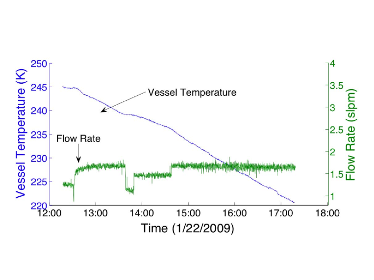
Starting with the system at room temperature and under vacuum, i.e., with no xenon gas present, the vessel temperature drops by only a few degrees when the cryocooler is activated, demonstrating that conductive cooling through the SS plumbing is negligible. Once xenon gas is introduced, the xenon vessel cools through convective heat exchange with the condenser, but the vessel temperature levels out at roughly 200 K in the absence of forced gas flow. We find that a minimum gas flow rate of about 1.2 SLPM is typically necessary to cool the xenon vessel from room temperature to the saturation temperature. At higher flow rates, from 2 to 4 SLPM, the vessel cools more quickly, as shown in Figure 5. The effects of increasing the flow rate even further are unclear. In one instance, increasing the flow rate to 5 SLPM decreased the vessel cooling rate, since the large amount of incoming warm gas heated the condenser above LXe temperature. However, in another instance, flows of 6.8 SLPM led to greater cooling rates in the vessel, so there may be other effects, such as pressure, that play a role. Cooling rates are discussed further in Section 5.2.
Forced gas flow may only be critical during the initial phase of vessel cooling. During one cool-down, gas flow and condensation were established, but the recirculation pump was unexpectedly halted, interrupting flow for 1 hour. Condensation continued during this time. Upon restarting the pump, the xenon gas pressure rose and would not stabilize until the pump was shut off again. However, condensation continued and the liquid level in the vessel rose without the forced flow. It is therefore not clear if the 1.2 SLPM flow rate is an absolute limit for vessel cooling; it may only be required to initialize condensation.
3.2 Gas flow during liquid maintenance
Once the vessel is cold and filled with liquid, it is easy to maintain at constant temperature and pressure for indefinite periods of time by forcing gas flow through the condenser and liquid vessel, using the gas return line as the exhaust. In this arrangement the gas circulates in a closed loop. This is generally our default configuration during liquid maintenance, and it allows for continuous purification of the xenon gas with a gas phase purifier. However, we have also studied the possibility of maintaining the liquid at constant temperature and pressure with the recirculation pump turned off. This situation could be important, for example, if the pump were to lose power unexpectedly. As detailed below, we find that it is possible, but more difficult, to achieve stability with the recirculation pump turned off.
Note that the xenon will thermodynamically recirculate at a small rate (a few SCCM) if the external gas plumbing allows gas to flow from the system output to the condenser input. This “thermal recirculation” is driven by the system heat leak, and it can be augmented by warming the liquid return line with its heater.
We achieve temperature and pressure stability most easily in the absence of forced gas flow by closing a valve in the external plumbing which prevents thermal recirculation. Under these conditions, we expect that no gas will enter the condenser input from the external system. Our flowmeter confirms this expectation. Nevertheless, we see through the large viewport that a steady stream of liquid drops falls into the vessel from above. This indicates that gas is counter-flowing up the liquid supply line from the vessel, liquefying, and falling back down, creating a closed heat exchange loop. This behavior is rather sensitive to the condenser temperature. For example, raising the pre-cooler temperature from 179.5 K to 180.5 K is enough to disturb the establishment of this heat exchange loop.
If we turn off the external recirculation pump without preventing thermal recirculation, then we usually find that condensing slows or stops, and that the system temperature and pressure slowly rise. Since the previous tests show that the system is able to condense the cold counter-flowing gas from the LXe vessel, this behavior could indicate that the extra heat load from the room temperature gas is too large. It is possible that this situation could be remedied by improving the cooling power of the condenser, particularly that of the post-cooler. Also note that if we encourage thermal recirculation with the heater, this makes the situation worse, increasing the rate of temperature and pressure rise.
On the other hand, if we establish the internal heat exchange loop by preventing external thermal recirculation, and we allow the system to run in this mode for several hours, we find that opening the external valve to allow thermal recirculation does not disturb the system stability. That is, the system behaves as if the valve were still closed.
4 Operation
The operation of the system is divided into four stages: preparation, vessel cool-down and filling, liquid maintenance, and recovery.
4.1 Preparation
To remove impurities in the system, the condenser and vessel are evacuated to 10-7 torr using a turbomolecular pump backed by a dry scroll pump. The cryostat is evacuated to 10-3 torr using a similar configuration, and it is pumped continuously while the cryocooler is running. A xenon gas supply bottle with a regulator is opened, and the regulator is set to introduce gas at a pressure between 1000 and 1400 torr. The recirculation pump is turned on and set to a flow rate of at least 1.2 SLPM. The gas circulates though the condenser, vessel, and external plumbing, and optionally through a zirconium getter for purification [22]. The pressure regulator on the xenon gas supply bottle is left open to allow additional gas to enter the system as needed. The pre-cooler set point temperature is set to 179.5 K. Once this is done, the system is prepared for cool-down.
4.2 Vessel cool-down and filling
During the vessel cool-down and filling phase, the gas continues to circulate through the condenser, vessel, and external plumbing. As the gas cools and becomes more dense, and later as the gas liquefies, additional gas is delivered from the supply bottle to the system as needed to maintain a constant pressure. The total amount of xenon in the liquid system can be monitored by measuring the remaining pressure in the supply bottle.
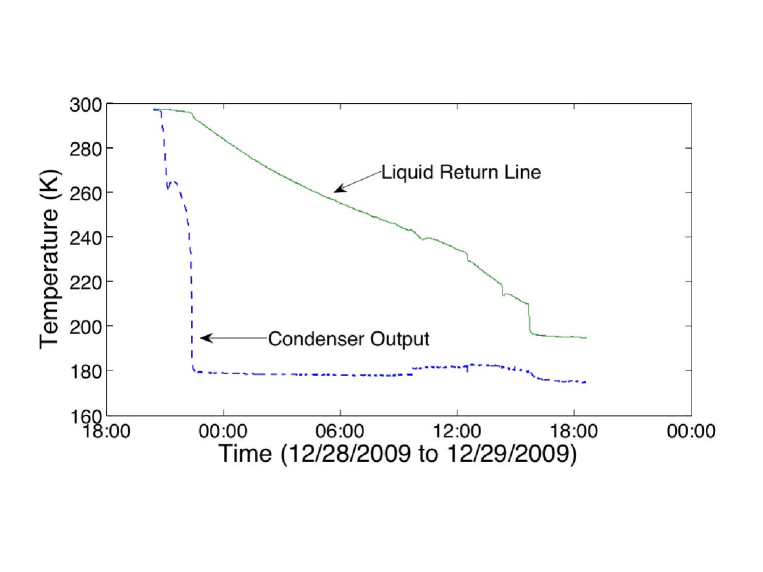
Figure 6 shows a temperature history of a typical cooldown as recorded by thermocouples at the output of the condenser and at the liquid return line near the bottom of the vessel. The cryocooler is activated to begin cooling the system, and the condenser temperature immediately drops. When the temperature reaches 260 K, the trim heaters turn on for the first time, momentarily warming the condenser. (The heaters are programmed to stay off when the condenser is above this temperature. This avoids overheating the cold head). After 1 hour, the temperature of the output of the condenser falls sharply, indicating LXe has formed and is pouring down into the vessel. After this sharp temperature decrease, drops of LXe can be seen via the viewport falling onto the bottom of the vessel and boiling away, and the temperature of the LXe return line decreases at about six times the previous rate. Note that this indicates that most of the cooling power is delivered to the vessel in the form of liquid xenon, rather than gaseous xenon.
The vessel cools this way for some time, typically about 8 hours, but it can be more or less depending on flow and pressure conditions. When the vessel temperature is low enough, liquid begins to collect in the bottom of the vessel. When enough liquid has collected, it overflows a small lip at the drain of the vessel that leads to the liquid return line. This “splash” brings the cold liquid into direct contact with the return line, causing the temperature there to quickly drop, as can be seen in Figure 6 around 16:00 on 12/29. This drop is correlated with a quick rise in the measured liquid level as the level meter is filled for the first time.
After the “splash” of liquid fills the return line, LXe continues to collect in the vessel. At this stage, the gas return bypass valve must be open to ensure that a high rate of gas flow can continue. (We typically keep this valve open through the entire process, from initial preparation through xenon recovery.) Condensing 1 kg of xenon takes 2-3 hours, depending on pressure and flow conditions.
4.3 Liquid Maintenance
Liquid can be maintained indefinitely in the vessel at constant temperature and pressure by keeping the pre-cooler set point temperature at 179.5 K, and by maintaining a nominal gas flow rate of 1-2 SLPM with the recirculation pump. As described in Section 3.2, the recirculation pump can also be turned off under certain conditions.
4.4 Xenon Recovery
The xenon is recovered by cryopumping. The room temperature gas supply bottle, which is made of aluminum, is placed in a liquid nitrogen bath, freezing any xenon inside. The supply bottle pressure regulator is fully opened to allow xenon gas to flow backwards through it. In addition, a bypass valve which is connected in parallel with the pressure regulator can be opened to reduce the pumping impedance further, but this is usually not necessary.
Finally the cryocooler is turned off and the LXe is allowed to warm, raising the vapor pressure. A hand valve between the liquid system and the cold supply bottle is used to manually regulate the gas flow rate. Care should be taken to avoid forming xenon ice by pumping too quickly. Recovery can be made quicker by heating the liquid return line directly with its integrated heater, or by filling the cryostat insulating vacuum with a dry gas such as nitrogen or helium to provide a thermal connection to the room temperature lab.
5 Measurements
5.1 Liquid Level
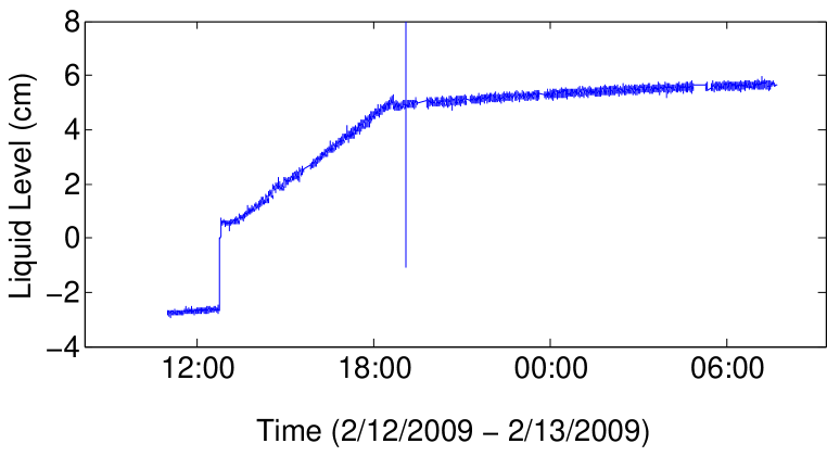
Figure 7 shows a sample plot of the height of LXe in the vessel during a cool-down. The gas pressure was 1000 torr. The recirculation pump forced a constant flow rate of 2.8 SLPM from 11:00 to 18:45 PM, after which it was turned off, and the xenon supply bottle was valved off. The initial rapid rise from -2.7 cm to 0.6 cm corresponds to the “splash” when liquid first overflows from the vessel into the return line. After that, a roughly linear increase in the height of the xenon can be seen as the storage vessel fills with liquid. A surprising feature is that from 6:45 PM until 9:00 AM the next day, the liquid level is seen to be rising slowly. This could indicate that the level sensor circuit has a slowly drifting systematic error.
5.2 Cooling Rate of the Vessel
The cooling rate of the stainless steel vessel was measured on two separate trials. During the first run, the flow rate was maintained at about 1.4 SLPM, with a xenon pressure of 1500 torr. The vessel cooled at 5.6 K/hr. During another run, the vessel cooled at 6.5 K/hr, with a much higher gas flow rate of 6.8 SLPM and pressure of 1500 torr. Using a specific heat for stainless steel of 500 J/kg/K, and estimating the vessel weight at 20 kg, we find that these cooling rates correspond to 15.5 W and 18.9 W of cooling power transferred to the vessel.
5.3 Condensation Rate
Two trials are presented in which the condensation rate is measured at various pressure and flow parameters. Condensation rate is measured during vessel filling in two ways. 1.) The mass of xenon remaining in the gas supply bottle is calculated from the known volume of the bottle, the measured pressure, and the density of xenon gas at that pressure. (The density of xenon gas has a non-linear relationship to the pressure at typical bottle pressures, and this dependence must be taken into account.) The rate of decrease of source mass was then calculated using central differencing and equated to the rate of condensation in the liquid system. 2.) The height of xenon in the vessel is measured, and converted into a volume and mass using the known cylindrical geometry of the system and the density of LXe. The rate of change in liquid height then equates to the condensation rate. These two methods give results in good agreement with each other, although the liquid height method is complicated by the volume displacement of the irregularly shaped particle detector in the LXe vessel. In the following, we quote results based on the bottle pressure method.
In the first trial, the xenon gas pressure was set to 1550 torr, and the gas flow rate was varied. The condensation rates were 0.54 kg/hr for a flow of 2.65 SLPM and 0.61 kg/hr for a flow 3.89 SLPM. In a second trial, the gas pressure was set to 1000 torr. The recirculation flow rate was set to 2.8 SLPM for the bulk of the trial. Condensation rates between 0.36 and 0.40 kg/hr were observed.
The largest rate of condensation, 0.61 kg/hr, was observed at a high pressure and large recirculation rate, 3.89 SLPM and 1550 torr. This implies that 44% of the circulating gas is condensed in a single pass. A condensation fraction of 58% was also achieved, but only at the cost of a lower condensation rate of 0.54 kg/hr. Tests at a lower pressure of 1000 torr indicate both lower condensation rate, 0.36 kg/hr, and a lower efficiency of 36%. Thus, the condensation fraction depends moderately on pressure and flow.
Using the latent heat of vaporization of xenon, 12.64 kJ/mol, and the specific heat of xenon gas, 20.8 J/mol/K, we can calculate the cooling power implied by our condensing rates. For the largest condensation rate, 0.61 kg/hr, we find a cooling requirement of 3.5 W and a latent heat removal of 16.4 W, for a total of 19.9 W. This is similar to the 18 W of cooling power we estimated is delivered to the stainless steel vessel during cooling.
6 Discussion
We find that for reliable operation of our condenser it is essential to control the temperature at both the top and bottom. Initial tests in which the condenser was cooled only at the top showed that a large temperature gradient would appear along its length. In this arrangement, the top of the condenser must be over-cooled to allow liquefaction to occur in the lower portion of the condenser. This leaves the condenser prone to ice formation, particularly if the gas flow rate suddenly decreases, removing a heat source.
With a dual control mechanism, both ends of the condenser are cooled, ensuring that temperature gradients are small. In addition, the two thermodynamic functions of the condenser (cooling warm gas and liquefaction) are separated spatially in the condenser, allowing for semi-independent temperature regulation with a pre-cooler and a post-cooler. This gives the condenser the flexibility to adjust to changing conditions, such as a change in the gas flow rate. In practice, our post-cooler temperature is usually above its set point temperature during condensation, and therefore its trim heater plays little role. Nevertheless, the additional cooling provided by the second stage of the cold head through the post-cooler improves temperature uniformity in the condenser, leading to more robust operation. To achieve greater control in the future, we intend to increase the cooling power of the post-cooler by reducing its thermal resistance.
Xenon ice formation is a dangerous problem for external condensers such as the one described here. Ice can block the flow of liquid and gas to the xenon vessel. Since the xenon flow is the only cooling mechanism for the vessel, its interruption can lead to a dangerous rise in system temperature and pressure. Our design is particularly sensitive to this problem, because the helical coil of the condenser has a cross-sectional outer diameter of only 1/4”. Therefore even a small amount of ice can lead to flow blockage. A condenser coil made from larger diameter tubing may improve the situation, or perhaps a condenser with an altogether different geometry may be better. For our purposes, however, the current design has proved to be adequate with appropriate safeguards.
Gas flow is essential for transferring the cooling power from the condenser to the xenon vessel, and a xenon gas return line from the top of the vessel greatly improves the effectiveness. There is a minimum flow rate necessary to cool the vessel to LXe temperature, and the condensation rate increases, albeit only slightly, with increasing flow. Cryopumping can serve as the method for forcing flow, but this is an awkward process that consumes large amounts of liquid nitrogen, and flow must be interrupted frequently to warm and cool the supply and recovery bottles. Therefore we find it is very useful to have a recirculation pump. Using the pump, gas flow can be easily maintained for days at a time, and with an inverter controller, the flow rate can be dialed to a desired value for easy testing. The main drawback to the pump is a loss of purity: our custom pump contains a teflon sleeve which is a source of outgassing and teflon debris in the system. These problems can be solved with purifiers and filters, however.
7 Conclusion
We have described a system for condensing and storing xenon where the source of cooling power has been removed from the vicinity of the liquid storage vessel, facilitating the introduction of instruments and materials to the vessel.
Condensation rates as high as 0.61 kg/hr were achieved, after an initial cool-down period of 8-10 hours. This corresponds to a condensation fraction of 44% and a cooling power of about 20 W. Changes in condenser design may be able to improve the condensation fraction and cooling power. Our design includes a two-stage cooling system for improved temperature uniformity and control. We find that a nominal gas flow rate is important for delivering cooling power to the vessel, and that a dedicated gas return line is useful for maintaining this flow when the vessel is filled with liquid.
8 Acknowledgments
We thank John Carriker for his many contributions to the system described in this article. This work was supported by award number 0652690 from the National Science Foundation.
References
- [1] W. H. Lippincott, et. al., “Scintillation time dependence and pulse shape discrimination in liquid argon”, Phys. Rev. C 78, 035801 (2008), arXiv:0801.1531[nucl-ex].
- [2] K. Abe et. al. “The XMASS experiment”, J. Phys.: Conf. Ser. 120 042022 (2008)
- [3] G.J. Alner, et. al. (ZEPLIN collaboration), “Limits on spin-dependent WIMP-nucleon cross-sections from the first ZEPLIN-II data”, Phys. Lett. B 653:161-166 (2007), arXiv:0708.1883v1.
- [4] J. Angle, et. al. (XENON collaboration), “First Results from the XENON10 Dark Matter Experiment at the Gran Sasso National Laboratory”, Phys. Rev. Lett. 100:021303 (2008), arXiv:0706.0039v2.
- [5] www.luxdarkmatter.org.
- [6] P. Benetti, et. al. (WARP collaboration), “First results from a Dark Matter search with liquid Argon at 87 K in the Gran Sasso Underground Laboratory”, Astropart. Phys. 28:495-507 (2008), arXiv:astro-ph/0701286v2.
- [7] M. Laffranchi and A. Rubbia (ArDM collaboration), “The ArDM project: a liquid argon TPC for dark matter detection”, arXiv:hep-ph/0702080v1.
- [8] C. Hall, “Searching for Double Beta Decay with the Enriched Xenon Observatory”, Proceedings of the 9th Conference on the Intersections of Particle and Nuclear Physics (CIPANP 2006), AIP Conf. Proc. 870:532-535, 2006.
- [9] A. Badertscher (ICARUS collaboration), “The ICARUS project: a 3000 t LAr TPC for neutrino physics and a search for nucleon decays” Nucl. Instr. Meth. A 535, 129 (2004).
- [10] S. Ritt (MEG collaboration), “Status of the MEG experiment ” Nucl. Phys. B Proc. Suppl. 162, 279 (2006).
- [11] M. Danilov, et. al. (EXO collaboration), “Detection of very small neutrino masses in double beta decay using laser tagging”, Phys. Lett. B 480, 12 (2000).
- [12] T. Haruyama, “Progress of xenon liquefaction technology by using a pulse tube cryocooler”, 2005 IEEE International Conference on Dielectric Liquids 26, 353 (2005).
- [13] C. Wang, “Helium liquefaction with a 4 K pulse tube cryocooler”, Cryogenics, 41, 491 (2001).
- [14] C. Wang, “Efficient helium recondensing using a 4K pulse tube cryocooler”, Cryogenics 45, 719 (2006).
- [15] C. Wang and R.G. Scurlock, “Improvement in performance of cryocoolers as condensers”, Cryogenics 48, 169 (2008).
- [16] Model PT805 from Cryomech, Inc., 113 Falso Drive, Syracuse, New York, 13211, www.cryomech.com.
- [17] Model Cni16D from Omega Engineering, Inc., One Omega Drive, Stamford, Connecticut, 06907-0047, www.omega.com.
- [18] Dayton model 3N694BA.
- [19] Frenic-Mini Type FRNF25C1S-6U from Fuji Electric, www.fujielectric.com.
- [20] Model PCI-6259 from National Instruments Corp., 11500 N Mopac Expwy, Austin, TX 78759-3504, www.ni.com.
- [21] Model 1512 Sentridial from Zetron, Inc., PO Box 97004, Redmond, WA 98073-9704, www.zetron.com.
- [22] SAES Monotorr purifier model PS4-MT3, www.saespuregas.com.