Viscous cavity damping of a microlever in a simple fluid
Abstract
We consider the problem of oscillation damping in air of a thermally actuated microlever as it is gradually approached towards an infinite wall in parallel geometry. As the gap is decreased from 20 down to 400 , we observe the increasing damping of the lever Brownian motion in the fluid laminar regime. This manifests itself as a linear decrease with distance of the lever quality factor accompanied by a dramatic softening of its resonance, and eventually leads to the freezing of the CL oscillation. We are able to quantitatively explain this behavior by analytically solving the Navier-Stokes equation with perfect slip boundary conditions. Our findings may have implications for microfluidics and micro/nano-electromechanical applications.
pacs:
47.61.Fg, 47.15.Rq, 85.85.+j, 07.79.LhMicro-
and nano-scale mechanical levers are increasingly used as sensors
and actuators in a large variety of fundamental studies and
applications. Mass detection at the zeptogram scale Ekinci ,
sub-attonewton force detection rugar01 and optical cooling
of microlevers cooling are among the most spectacular
achievements of oscillating cantilevers (CLs). These realizations
mainly rely upon the extraordinary high quality factors (Q) of
oscillating CLs in vacuum and/or cryogenic temperatures where
values exceeding 100 000 are attainable. Clearly, maintaining such
performances in air or in a liquid is a very challenging issue as
oscillation damping in the surrounding fluid dramatically degrades
Q. This has been partially circumvented by using ultrasmall
self-sensing nano-electromechanical systems (NEMS, i.e.,
actuated mechanical devices made from submicron mechanical
components facing each other) operating in ambient conditions of temperature and pressure Roukes2007 .
However, oscillating CLs are also used in viscous
environments on many occasions Charlaix1 ; Shih ; Hansma ; Aime .
In Atomic Force Microscopy (AFM) for example, a resonant CL is
used to measure surface topography and physico-chemical properties
of various materials not only in air but also in
liquids Raman for, e.g., visualizing dynamic biomolecular
processes at video rate muller . The interaction
between an AFM CL and a surrounding liquid has been used for a
distance calibration in a Casimir force measurement Cap1
and has led very recently to the spectacular demonstration of a
repulsive Casimir force Cap3 . Therefore, the need for a
quantitative study of the CL behavior in viscous micro- and
nano-scale environments is increasing. In this letter, we report
such a quantitative study and show, down to the
submicron scale and in the demanding plane-plane geometry, how
confinement and boundary conditions at the solid-fluid interfaces conspire to change the coupling to thermal bath and how
this can freeze
out the lever oscillation.
When a CL beam vibrates in a viscous fluid, the fluid
offers resistance to the beam displacement ENS ; Bhila . If
the CL is vibrating close to a solid surface, the behavior of the
fluid and, consequently, that of the lever are modified by the
surface due to confinement. The Navier-Stokes (NS) equations give
a complete description of the fluid behavior taking into account
the particular environment under analysis. However an analytical
solution of NS equations is possible only for a restricted number
of geometries and comparison of theory with experimentally
relevant configurations is in general a complex matter or is even
lacking, especially at the deep micron and submicron scales
Green ; Naik ; Paul ; Dorignac ; Basak ; Tung where boundary
conditions at the fluid-solid interfaces are strongly
modified Tabeling ; Chan ; Vinogradova ; Maali . In this work, we
focus on the dynamical behavior of a microlever close to a planar
rigid surface in the air. Provided that adapted boundary conditions are used, the NS equations can be solved
analytically for this plane-plane model geometry that mimics a
basic part of a MEMS (the counterpart of a NEMS in the micron
range) device operating in the air. This, combined with the use of
the fluctuation-dissipation theorem and of an experimental
arrangement specially designed to gain access to the intrinsic
behavior of the CL, enables us to make a quantitative comparison
between theory and experiment
in a wide range of cavity lengths down to a few hundreds of nanometers.
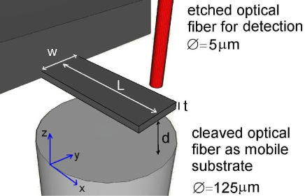
Our setup is shown schematically in Fig. 1. Its
first specification is that the CL - a commercial thin silicon AFM CL
removed for liquid imaging with dimensions - is actuated by the stochastic thermal noise
only. This induces sub-Angstrom oscillations at the CL resonance
frequency ( kHz), thereby allowing us to consider
the fluid in the cavity in the laminar regime. Second, the planar
rigid surface facing the CL to form a parallel-plate cavity is
made of a cleaved optical fiber with a diameter of 125
that is mounted over a three-axis inertial motor so as to be able
to adjust the cavity gap. This positioning system offers
a large displacement range (8 each axis full range) with a
good accuracy (40 per step). Finally, the CL Brownian motion
is measured by means of a non invasive interferometric
detection based on the use of a very thin optical fiber facing the
CL at a 2 distance. This fiber has been chemically etched
so as to reduce its diameter to 5 . This corresponds
basically to the fiber core diameter plus a residual amount of the
optical cladding for better light guidance. The large ratio in
excess of between the areas of the cleaved and detection
fibers insures that only the cleaved one induces air confinement,
not the etched one, which is used for detection purpose only.
Therefore, no additional uncontrolled confinement and damping are
produced by the detection fiber.
An AFM CL vibrating in a viscous fluid may be viewed as a driven and damped 1D harmonic oscillator whose equation of motion reads
| (1) |
where , , are the CL effective mass, time-dependent position, and stiffness, respectively, is the damping factor and the external (i.e., thermal) driving force. According to the fluctuation-dissipation theorem, the thermal Brownian motion of the CL at temperature is accounted for by a frequency independent force power spectrum defined as ( is the Boltzmann constant, the pulsation linked to the frequency ). Starting from Eq. 1 we obtain the CL displacement power spectrum as , where the CL transfer function is given by:
| (2) |
with . In the
limit of small damping,
i.e., , has a resonance at .
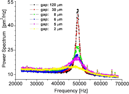
In Fig. 2, the experimental Brownian oscillation
power spectrum is presented as a function of frequency for
different cavity gaps . It is clearly seen that the resonance peak
dramatically broadens and softens to lower frequencies with
decreasing gap. Within the experimental accuracy, we find that
the area under the resonance curves in Fig. 2
remains constant and equals to the thermal energy. This shows that the CL damping increases with decreasing gap.
Now, we turn on to a quantitative analysis of the experiment. The
fluid responsible for the CL damping is the air confined between
the CL and the mobile fiber. The dynamic of such an incompressible
fluid is described by the NS equations
| (3) |
where is the fluid velocity, its density, its dynamical viscosity and the gas pressure. In the laminar regime, i.e., in the limit of small Reynolds numbers, Eq. 3 simplifies to . In order to solve the NS equations, one needs to know the specific boundary conditions existing at the fluid-solid interfaces (for simplicity we assume the cavity plates to be infinitely extended). While for macroscopic hydrodynamic applications one usually accepts that fluids do not slip against solid walls, this is generally not true for microfluidic problems involving MEMS or NEMS Tabeling . A critical parameter in this respect is the Knudsen number Tabeling which depends on the gas mean free path . For air at ambient conditions nm which leads here to . In this range of values, it is already known that fluid-slip can occur over a solid interface Tabeling ; Chan ; Vinogradova . In particular, partial fluid-slip has been recently observed in the plane-sphere geometry in air using an AFM in dynamic mode Maali . However, none of the previous works investigated the regime of Brownian oscillations with typical CL amplitudes nm much smaller than (i.e., ). In such a regime, boundary conditions are expected to be even more strongly modified Tabeling compared with the macroscopic regime although it is not yet known how much they are modified. Here, we make the hypothesis of perfect slip, historically anticipated by Navier Navier , for which friction along the solid interface is prohibited, and show that we can obtain a consistent quantitative description of our experimental data. This hypothesis results in a velocity gradient along the direction which leads to a Stokes friction coefficient:
| (4) |
where is the cantilever surface. The usual no-slip condition at the fluid solid interface would predict , in clear disagreement with the experiment. As a direct consequence, Eq. 4 leads to a much smaller decay of the friction force with than predicted usually.
Quantitative information on the damping factor is obtained from
the analysis of the CL quality factor. Both quantities are
linked together by the relation ,
which becomes for small gaps:
| (5) |
Eq. 5 predicts a linear dependence of with that can be compared with experiment.
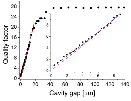
Fig. 3 depicts the quality factor as function of the cavity gap. Two different regimes can be distinguished. For large gaps above 40 , the quality factor remains constant. This is the unconfined fluid regime where no additional damping can take place with decreasing gap. For smaller gaps however, the quality factor tends to decrease with a decreasing gap. We will focus below on the small gap regime where the hypothesis of infinite planes is physically justified. Since the AFM CL has a surface 10 times smaller than the substrate fiber, the gap limit for the hypothesis of infinite planes to remain physically sound can be estimated by taking the apparent CL surface as reference, i.e. .
As shown in the inset of Fig. 3 the experimental results and the theoretical prediction of Eq. 5, with no adjustable parameter measure , coincide to within for gaps larger than 5 but for smaller separations, the agreement worsens to reach at the smallest gap, 400 . We interpret this difference with a residual small angular misalignment of the two facing parallel plates.
For small misalignment, the problem can be treated within an approximation similar to the Proximity Force Approximation (PFA) used, for instance, in the Casimir force formulation in the sphere-plane geometry PFA . In this approximation, the corrected damping factor becomes:
| (6) |
where is the shortest distance from the inclined CL to the substrate, and are the lateral tilt angles of the CL with the mobile surface in the and directions, respectively. The angle values that permit to reproduce the evolution of the disagreement between experiment and theory, as presented in Fig. 3, are . Considering these misalignment angles, the good agreement between theory and experiment can now be extended down to the smallest gap range that we have measured as can be seen in Fig. 3. Over the entire range , the remaining disagreement is only pachyderme .
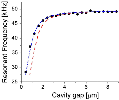
We now discuss the frequency softening of the CL oscillation, the other salient experimental fact revealed by Fig. 2. In the limit of large damping, i.e. the approximation no longer holds, the power spectrum of Eq. 2 has a down-shifted resonance pulsation given by:
| (7) |
Fig. 4 shows that the resonance frequency shift
can be extremely large. One step further below , a complete freezing of the CL
oscillation would have been observed. This was precluded by the residual angular misalignment discussed above. Taking into account for data
analysis of the misalignment obtained from Fig. 3, we can quantitatively model the measurements in Fig. 4
without any adjustable parameter whatsoever. Therefore, beside the CL width that governs the factor behavior at
large scale (Fig. 3), another shorter characteristic length is here emphasized in the submicron range, i.e. (around 500 nm in our case), which is the gap width cancelling the resonance frequency in Eq. 7. This characteristic length is determined by the CL dynamics and the fluid viscosity.
In conclusion, we have presented high sensitivity measurements of
the damping of a thermally driven CL in a simple fluid confined in
a microcavity formed by this CL facing an infinite wall. As the
cavity length decreases, the fluid confinement induces a dramatic
damping of the CL Brownian motion which can lead to its complete
freezing at small gaps. A consequence of our work is that micro- or nano-oscillators can
either present high Q factors or be overdamped systems depending
on their actual geometry, resonance frequency, oscillator
substrate gap and, of course, ambient viscosity. These findings may impact the design of modern NEMS and microfluidic devices since the dependence strongly reduces dissipation even for separations as large as thousands of mean free path (see Fig. 3). This behavior can be furthermore described
by solving the Navier-Stokes equation with perfect solid-fluid
slip boundary conditions. The agreement between experiment and our model is found over a broad
range of cavity lengths, including the submicron range. Interesting extensions of the present work include the study of parameters affecting boundary conditions, such as external actuation of CLs (to obtain large oscillation amplitude) newraman , nanostructuration Roukes2007 , and surface chemical properties Aime .
We are grateful to Giovanni Ghigliotti for helpful discussions. Our thin etched optical fiber has been prepared
by Jean-Francois Motte. This research was partly supported by a “Carnot-NEMS” collaborative grant between CEA-LETI and Institut Néel.
References
- (1) Y. T. Yang, et al., Nano Lett. 6, 583 (2006).
- (2) H. J. Mamina and D. Rugar, Appl. Phys. Lett. 79, 3358 (2001).
- (3) K. Karrai, Nature (London) 444, 41 (2006); C. Metzger, et al., Phys. Rev. Lett. 101, 133903 (2008); G. Jourdan, et al., Phys. Rev. Lett. 101 133904 (2008).
- (4) Mo Li, et al., Nature Nanotech. 2, 114 (2007).
- (5) C. Cottin-Bizonne, et al., Phys. Rev. Lett. 94, 056102 (2005).
- (6) W. Y. Shih, et al., J. Appl. Phys. 89, 1497 (2001).
- (7) P. K. Hansma, et al., Appl. Phys. Lett. 64, 1738 (1994).
- (8) A. Maali, et al., Phys. Rev. Lett. 96, 086105 (2006).
- (9) A. Raman, et al., Nanotoday 3, 20 (2008).
- (10) T. Ando, et al., Prog. Surf. Science 83, 337 (2008).
- (11) J. N. Munday, et al., Phys. Rev. A 78, 032109 (2008).
- (12) J. N. Munday, F. Capasso, and A. Parsegian, Nature (London) 457, 170 (2009).
- (13) L. Bellon, J. Appl. Phys. 104, 104906 (2008).
- (14) R. B. Bhiladvala and Z. J. Wang, Phys. Rev. E 69, 036307 (2004).
- (15) C. P. Green and J. E. Sader, J. Appl. Phys. 98, 114913 (2005).
- (16) T. Naik, et al., Sensor and Actuators A: Physical 102, 240 (2003).
- (17) M. R. Paul and M. C. Cross, Phys. Rev. Lett. 92, 235501 (2004).
- (18) J. Dorignac, et al., Phys. Rev. Lett. 96, 186105 (2006).
- (19) S. Basak, et al., J. Appl. Phys. 99, 114906 (2006).
- (20) R. C. Tung, et al., J. Appl. Phys. 104, 114905 (2008).
- (21) P. Tabeling, Introduction to microfluidics (Oxford University Press, USA, 2006).
- (22) D. Y. C. Chan, and R. G. Horn, J. Chem. Phys. 83, 5311 (1985).
- (23) O. I. Vinogradova, Langmuir 11, 2213 (1995).
- (24) A. Maali and B. Bhushan, Phys. Rev. E 78, 027302 (2008).
- (25) The CL tip has been removed by focused-ion-beam milling.
- (26) S. Goldstein, Ann. Rev. Fluid. Mech. 1, 1 (1969).
- (27) The CL dimensions have been measured by electron microscopy. The air viscosity was taken as . The CL stiffness has been experimentally determined from Fig. 2 using the energy equipartition theorem.
- (28) B. V. Derjaguin, et al., Q. Rev. Chem. Soc. 10, 295 (1956).
- (29) Following Ref. Aime , the ultra small CL oscillation precludes any mass addition to the lever, in contrast with Ref. Naik where this effect is dominant for actuated macroscopic levers.
- (30) R. A. Bidkar, et al., Appl. Phys. Lett. 94, 163117 (2009).