From Graphene constrictions to single carbon chains
Abstract
We present an atomic-resolution observation and analysis of graphene constrictions and ribbons with sub-nanometer width. Graphene membranes are studied by imaging side spherical aberration-corrected transmission electron microscopy at 80 kV. Holes are formed in the honeycomb-like structure due to radiation damage. As the holes grow and two holes approach each other, the hexagonal structure that lies between them narrows down. Transitions and deviations from the hexagonal structure in this graphene ribbon occur as its width shrinks below one nanometer. Some reconstructions, involving more pentagons and heptagons than hexagons, turn out to be surprisingly stable. Finally, single carbon atom chain bridges between graphene contacts are observed. The dynamics are observed in real time at atomic resolution with enough sensitivity to detect every carbon atom that remains stable for a sufficient amount of time. The carbon chains appear reproducibly and in various configurations from graphene bridges, between adsorbates, or at open edges and seem to represent one of the most stable configurations that a few-atomic carbon system accomodates in the presence of continuous energy input from the electron beam.
Carbon is one of the most important elements that occurs in numerous allotropes, displays an exceedingly rich chemistry, and is contained in a staggering number of compounds. The two solid crystalline forms, graphite and diamond, are known since ancient times, while the more recently discovered fullerenes Kroto et al. (1985), carbon nanotubes Iijima (1991); Saito et al. (1998), and graphene Novoselov et al. (2004); Geim and Novoselov (2007) make up a large part of today’s nanotechnology research. Thus, a wide range of allotropes and structural species with all dimensionalities is available for research and applications today. Now, we present a simple and reliable synthesis of a truly one-dimensional carbon species, a single-atomic linear carbon chain. Evidence of such carbon chains has been observed in spectral signatures from space Kroto et al. (1987) and in laboratory experiments Heath et al. (1987); Troiani et al. (2003); McCarthy et al. (2008); however their formation mechanisms have remained unclear and the chemical and physical properties mostly undiscovered. Here, we form monoatomic carbon chains by shrinking a graphene constriction under electron irradiation. We follow their formation with atomic resolution and sufficient sensitivity to detect every carbon atom that remains stable for at least one second. We find that graphene constrictions deviate from the hexagonal structure as their width is reduced below one nanometer, and intermediate structures between a graphene constriction and a carbon chain are dominated by pentagons and heptagons. The carbon chain formation from shrinking a graphene constriction indicates a possible site specific fabrication, which is the first step to a further analysis or technological application.
Our study of graphene membranes reveals an efficient formation mechanism of carbon chains. Indeed, these chains appear almost-inevitably in these ultra-thin graphitic samples after a sufficiently high dose of electron irradiation. Holes and constrictions form in the process of irradiation and, most surprisingly, most of the constrictions turn into carbon chains before ultimately detaching. Thus, instead of a synthesis from smaller units, the carbon chains form by self-organization from a continuously diluted set of carbon atoms in the presence of ionizing irradiation. In addition, the amorphous, carbonaceous adsorbates on the graphene membranes form carbon chains while shrinking under electron irradiation, and bended chains appear at the free edges of graphene. This variety of conditions in which they form indicates that these chains are a preferential and stable configuration at a low density of carbon atoms, not limited to graphene membranes. Further, by shrinking a graphene ribbon Son et al. (2006) in an electron beam under continuous observation, we investigate the transition from a quasi-2D material to a 1D structure. As the width drops below ca. 1 nanometer, the structural behaviour of the ribbon and its two edges becomes distinctively different from that of a semi-infinite sheet with one open edge Girit et al. (2009); Koskinen et al. (2008); Jun (2008), and thus marks the transition from a surface-dominated to an edge-dominated regime. Stable planar -bonded reconstructions of the graphene bridge are observed as intermediate configurations.
Graphene membranes are prepared by mechanical cleavage of graphite and transfer to commercially available transmission electron microscopy (TEM) grids as described previously Meyer et al. (2008a). The presence of a single layer is verified by electron diffraction Meyer et al. (2007). TEM investigations are carried out using an imaging-side spherical aberration corrected Titan 80-300 (FEI, Netherlands), operated at 80kV. The electron beam current density is ca. . The spherical aberration is set to 20m and imaging is done at Scherzer conditions Spence (2003). The extraction voltage of the field emission gun is reduced from its standard value (3.8kV) to 1.7kV in order to reduce the energy spread of the source. This results in a clear improvement of contrast and resolution, both of which are limited by chromatic aberrations of the objective lens at 80kV operating voltage.
A key advantage of spherical aberration corrected TEM is that the point resolution can be set approximately to the information limit of the microscope. In this way, effects of delocalization are reduced Lentzen et al. (2002). Thus, for a sample that is imaged at optimum focus conditions and that is thin enough to neglect multiple scattering, the images can be directly interpreted in terms of the atomic structure. For a single layer of carbon, these requirements are easily fulfilled. Atoms appear black at our conditions.
Holes appear in graphene membranes during electron irradiation, as described previously Fischbein and Drndic (2008); Girit et al. (2009). We look for configurations where two nearby holes are present in a clean region of the graphene sheet. Although we look here for the coincidental formation of two nearby holes, we note that it has been demonstrated by Fischbein et al. that an arbitrary configuration of holes can be made in a controlled position by electron irradiation Fischbein and Drndic (2008). At an electron energy of 80kV, atoms at the graphene edges are removed while the continous graphene membrane areas are very stable. Thus, as the holes grow under continuous electron irradiation, the graphene bridges between nearby holes inevitably shrink but are not damaged otherwise. Eventually, narrow graphene constrictions form between adjacent holes. We record a continuous sequence of images on the CCD camera, using an exposure time of 1 second at 4 second intervals. Reconstructions that affect not only the edges but the entire graphene ribbon are frequently observed at widths of less than 1 nanometer. Finally, a single chain with a typical length of 10-15 carbon atoms is seen in more than 50% of the cases as the final product of bridge thinning, which then remains stable for up to two minutes under our intense electron beam.
A single layer graphene membrane with two holes, separated by a ca. 1nm wide graphene bridge, is shown in Fig. 1a. Figs. 1b-g show the same graphene constriction at later times, along with best-fit atomic models and image simulations. A video of this process is shown in the supplementary video S1 (supplementary videos S2, S3 show the time evolution of two similar graphene constrictions). Again, the atomic model is easily derived because the dark contrast in this spherical aberration corrected image can be directly interpreted in terms of the atomic structure. Further, the structure appears to remain planar, i.e. no indication of two carbon atoms on top of each other in the projected structure was observed (small out-of-plane distortions are still possible, and indeed likely, in a carbon structure with multiple pentagons and heptagons). The atomistic model is generated with the ghemical software Acton et al. , and the TEM image calculation is obtained using multislice software Chuvilin and Kaiser (2005).
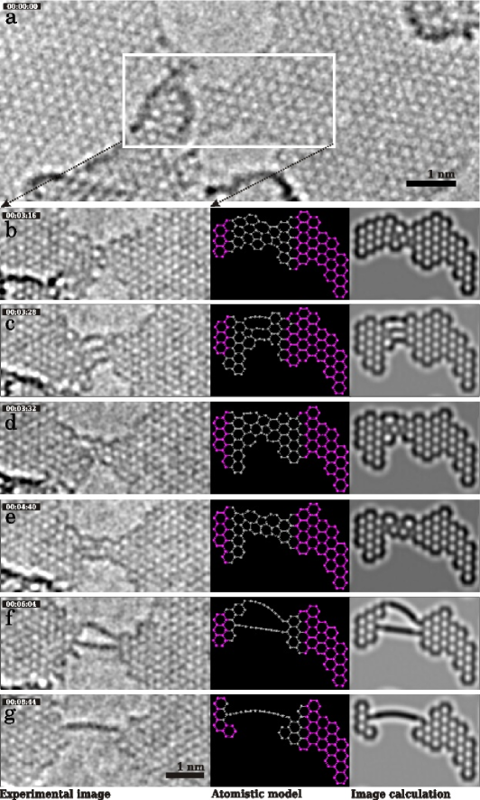
The reconstructions that occur in the time evolution, with continuous energy input from the electron beam, are indeed remarkable. In this example, the graphene bridge incorporates pentagons and heptagons (Fig. 1b), converts into three parallel carbon chains (Fig. 1c), transforms back into a structure with multiple polygons (5, 6, 7, 8 sides, Fig. 1d, e), and finally becomes a double and single carbon chain before the two holes merge into one (Fig. 1f, g). Further, it can be seen in the supplementary video S1 that the end point of the carbon chain, i.e. its connection to the hexagonal mesh of the graphene sheet, drifts between nearby edge atoms multiple times before the chain finally breaks. Similar transitions or reconstructions were observed many times in different samples, and are separately discussed in the following paragraphs.
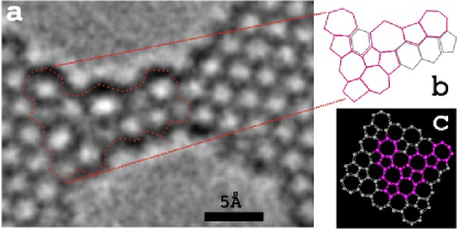
We begin our discussion with the transformations from a hexagonal structure to meshs that are dominated by pentagons and heptagons. From the observed structures alone, it appears that a variety of (seemingly random) combinations of pentagons, heptagons or higher polygons can be generated within the graphene bridge. The reason for these reconstructions may be twofold: As an intrinsic origin, calculations of edge stress Jun (2008) and edge reconstructions Koskinen et al. (2008) indicate that unperturbed graphene edges might not be the optimum configuration. Thus, reconstruction of the entire structure can be expected once the graphene ribbon is sufficiently narrow. As an extrinsic driving force, energy input from the electron beam is present, which can help e.g. to overcome activation barriers. Indeed, the dominant effect of the electron irradiation at 80kV in graphene is not atom removal, but atom rearrangement (e.g. the Stone-wales type bond rotation Stone and Wales (1986)). Thus, structures that are random (to some extent) are formed locally. At the same time, these structures are observed with single-atom precision. We can now gain crucial insights by studying the stability (under the beam) of the observed structures, since “stable” configurations would be expected to last longer than unstable ones. For example, we find that the configuration of Fig. 1e turns out to be stable for 2 minutes in the intense electron beam, which corresponds to an electron dose of and is longer than all other multiple-polygon type structures observed within our data. Fig. 2a shows an image with better signal-to-noise ratio (by averaging of 10 CCD frames) of this structure. From the atomic configurations (Figs 2b,c), it turns out that the structure is locally that of pentaheptite, a carbon allotrope that was predicted to be stable in 1996 Crespi et al. (1996) but never observed experimentally so far.
As a generalization, it appears promising to look for stable configurations with the continuous “randomization” of some atoms by the electron beam. In this way, configurations with local energetic minima can be discovered (such as pentaheptite) which are not experimentally accessible otherwise. Graphene bridges provide an ideal starting point for such a study: Bond rotations were observed previously in graphene without holes but then they are constrained by the continuous membrane, and thus relax to the unperturbed structure Meyer et al. (2008b). Graphene edges, the boundary of a semi-infinite sheet, allow to study the migration of edge atoms but still the reconstructions do not seem to penetrate into the graphene sheet Girit et al. (2009) (topological changes are limited to the edge polygons). Graphene bridges or ribbons are only constrained in one direction and can reconstruct more freely, but at the same time the structures remain sufficiently planar and stable for a direct analysis by low voltage, aberration corrected transmission electron microscopy. Thus, we expect that a further study of intermediate structures in graphene bridges, with particular respect to their stability, can provide further insights on the complicated bonding behaviour in carbon materials.
We now turn to the chain-type configurations that are frequently observed as the graphene bridge is ultimately narrowed down to a few-atom or single-atom width. It is obvious that with only a random removal of atoms, even of only the edge atoms from a graphene bridge, the formation of a carbon chain by coincidence would be highly unlikely. However, more than 50% of the graphene constrictions display one or several carbon chains before the two holes merge into one. Therefore, it must be atomic rearrangements along with the continuous removal of atoms in the electron beam that leads to carbon chains as the final product, the thinnest possible carbon bridge. Indeed, several narrow bridges convert into two parallel chains (Fig. 1c shows a rare case of even three) which indicates that this transformation is energetically favoured rather than caused by only the removal of atoms.
There is no doubt that these chains must be made from carbon, since we can follow, atom by atom, the transition from graphene to these chains (Fig. 1, and supplementary video). Contrast and observed width in the experiment is in agreement with the calculation for single-atomic chains (Figs. 1f, g). Further, the amount of carbon material that is present just before the transitions can not account for more than a single-atomic chain in each of the dark lines. Several of these chains can occur in parallel (Fig. 1c, f) and even convert back to a (2D) planar covalent network (Fig. 1c to d). The chain structures may be of the double-bonded (cumulene-type) or alternating single-triple bonded (polyyne-type) structures Bodart et al. (1987); Khoo et al. (2008); McCarthy et al. (2008), or possibly the linear alkane or polyacetylene type chains. The first two structures, cumulene (……) or poly-yne type (……) are linear chains and in good agreement with the observation; calculations show that the number of carbon atoms (even or odd) determines which case is present Bodart et al. (1987); Khoo et al. (2008). In our experiment, the signal to noise ratio is not sufficient to distinguish the two types. The last two structures, an alkane chain or polyacetylene, are angled chains with bonds at 120° and 109.5°, respectively. No indication of this zig-zag structure is seen in our chains; however, its visibility depends on whether the correct projection occurs in the experiment. If we assume that random orientations occur in the experiment, then a sufficent number of chains was observed to rule out these angled types of chains.
Similar carbon chain configurations have been observed previously in carbon nanotube samples Troiani et al. (2003); Yuzvinsky et al. (2006) but were often not stable enough for recording a TEM image Yuzvinsky et al. (2006); Ajayan et al. (1998). In our case, more than 50% of the graphene constrictions convert into a carbon chain at the end of the thinning process. The carbon chains are frequently stable for one minute, and sometimes up to two minutes, in our rather intense electron beam. One minute corresponds to a dose of . This result is particularly surprising in the light of commonly assumed radiation dose limits for organic molecules, which are on the order of Malac et al. (2007), and thus five orders of magnitude lower than our doses. It has been speculated that the high conductivity of the graphene sheet reduces the effect of ionization damage Fill et al. (2008). Of course, a carbon chain is not a complex organic structure, but it does represent an organic substance and constitutes a building block of many more complex molecules. These results indicate that radiation damage mechanisms are not well understood; experiments at varying electron energies should help to gain further insight.
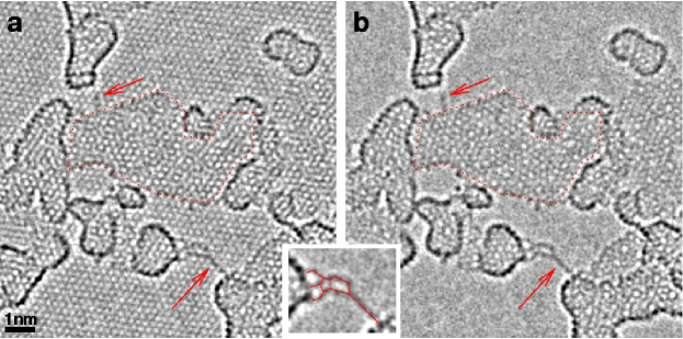
In addition to these free-hanging carbon chains, we observe carbon chains that are supported by a graphene sheet, as observed before Meyer et al. (2008c). We find that this type of chain frequently occurs where amorphous adsorbates shrink under electron irradiation, and forms similar to the aforementioned type, but now from constrictions in the contamination layer. The supplementary videos S4, S5 show this process. Fig. 3 shows two carbon chains that are attached to larger adsorbates at their end points. Some of the adsorbates are single-layer networks of carbon atoms, as indicated in Fig. 3. Even though we find a slight preference of these chains to align with the zig-zag direction of the underlying graphene lattice, again no indication of a zig-zag shape (as expected for an alkane- or polyacetylene-type chain) is seen in the carbon chain itself. Thus, we confirm their structure as either cumulene or poly-yne type as described above. For the case of chain formation from carbon contamination, it is the low-contrast background of the graphene support that enables the visualization of this process by TEM.
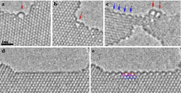
As a third configuration, we observe carbon chains that form loops along graphene edges. Although more rare than the previously described chains, they can still be reliably found by observing graphene hole edges for a longer time. Figure 4 shows three examples of carbon chains that have separated from the edge. Frequently they merge back into the graphene edge at a later time. These additional ways of formation confirm that the carbon chains are a preferred configuration in a continuously diluted set of carbon atoms, not limited to graphene constrictions.
Finally, we discuss the edge reconstructions that are shown in Figs. 4c,e). Fig. 4e shows an edge that is terminated by an alternating sequence of pentagons and heptagons with a period that is twice as large as that of the zig-zag edge. It constitutes one of the edge reconstructions predicted in Ref. Koskinen et al. (2008). For this edge, the switching between the two configurations was observed several times as shown in Figs. 4d,e and in the supplementary video S6. During TEM observation, all the edges of graphene are continously changing, due to the energy input from the electron beam Girit et al. (2009). However, as this edge switches from a well defined zig-zag edge to the reconstructed configuration and back multiple times in-between two exposures, it can not be a coincidental arrangement formed by random single-atom knock-on events. More likely, these are two stable configurations, and the energy input from the beam provides the activation energy that is required to switch between the two cases. However, this implies that the energy input from the beam has a non-local effect (possibly via excitation of a phonon) which changes an entire ca. 5 nm long edge in one step, rather than just kicking individual atoms to a different position.
In conclusion, we have shown the transformation from graphene nano-ribbons to single carbon chains. Planar, -bonded networks that deviate from the hexagonal structure appear as intermediate reconstructions as the graphene ribbon width shrinks below 1 nanometer. Many electronic applications of graphene require nanometer-scale graphene ribbons or graphene constrictions. Thus, on the one hand, reconstructions have to be considered in ultra-narrow ribbons, while on the other hand carbon chains might be useful as electronic component and represent the ultimate constriction in graphene. The chains form efficiently by self-organization during continuous removal of atoms from a graphene bridge. Further, they are observed at edges, or form from constrictions in the carbonaceous contamination. In other words, the “precursor” material for the chains ranges from highly crystalline (graphene) to amorphous (adsorbate) carbon, which indicates that a rather general self-organization process is observed here. Finally, the high robustness under irradiation of these linear carbon chains combined with the ease of electron beam fabrication at the nm scale can provide a route to a synthesis of devices and for further studies of these structures.
References
- Kroto et al. [1985] H. W. Kroto, J. R. Heath, S. C. O’Brien, R. F. Curl, and R. E. Smalley. C60: Buckminsterfullerene. Nature, 318:162, 1985.
- Iijima [1991] Sumio Iijima. Helical microtubules of graphitic carbon. Nature, 354:56, 1991.
- Saito et al. [1998] R. Saito, G. Dresselhaus, and M. S. Dresselhaus. Physical Properties of Carbon Nanotubes. Imperial College Press, London, 1998.
- Novoselov et al. [2004] K. S. Novoselov, A. K. Geim, S. V. Morozov, D. Jiang, Y. Zhang, S.V. Dubonos, I.V. Grigorieva, and A.A. Firsov. Electric field effect in atomically thin carbon films. Science, 306:666, 2004.
- Geim and Novoselov [2007] A. K. Geim and K. S. Novoselov. The rise of graphene. Nature materials, 6:183, 2007.
- Kroto et al. [1987] H. W. Kroto, J. R. Heath, J. R. O’Brien, S. C. Curl, and R. E. Smalley. Long carbon chain molecules in circumstellar shells. Astrophysical Journal, 314:352, 1987.
- Heath et al. [1987] J. R. Heath, Q. Zhang, S. C. O’Brien, R. F. Curl, H. W. Kroto, and R. E. Smalley. The formation of long carbon chain molecules during laser vaporization of graphite. J. Am. Chem. Soc., 109:359, 1987.
- Troiani et al. [2003] H. E. Troiani, M. Miki-Yoshida, G. A. Camacho-Bragado, M. A. L. Marques, A. Rubio, J. A. Ascencio, and M. Jose-Yacaman. Direct observation of the mechanical properties of single-walled carbon nanotubes and their junctions at the atomic level. Nano Lett., 3:751, 2003.
- McCarthy et al. [2008] M. C. McCarthy, M. J. Travers, A. Kovacs, W. Chen, S. E. Novick, C. A. Gottlieb, and P. Thaddeus. Detection and characterization of the cumulene carbenes h2c5 and h2c6. Science, 275:518, 2008.
- Son et al. [2006] Y. W. Son, M. L. Cohen, and S. G. Louie. Energy gaps in graphene nanoribbons. Phys. Rev. Lett., 97:216803, 2006.
- Girit et al. [2009] C. O. Girit, J. C. Meyer, R. Erni, M. D. Rossell, C. Kisielowski, L. Yang, C.-H. Park, M. F. Crommie, M. L. Cohen, S. G. Louie, and A. Zettl. Graphene at the edge: Stability and dynamics. Science, 23:1705, 2009.
- Koskinen et al. [2008] P. Koskinen, S. Malola, and H. Hakkinen. Self-passivating edge reconstructions of graphene. Phys. Rev. Lett., 101:115502, 2008.
- Jun [2008] S. Jun. Density-functional study of edge stress in graphene. Phys. Rev. B, 78:073408, 2008.
- Meyer et al. [2008a] J. C. Meyer, C. O. Girit, M. F. Crommie, and A. Zettl. Hydrocarbon lithography on graphene membranes. Appl. Phys. Lett., 92:123110, 2008a.
- Meyer et al. [2007] J. C. Meyer, A. K. Geim, M. I. Katsnelson, K. S. Novoselov, D. Obergfell, S. Roth, C. Girit, and A. Zettl. On the roughness of single- and bi-layer graphene membranes. Solid State Communications, 143:101, 2007.
- Spence [2003] J. C. H. Spence. High-Resolution Electron Microscopy. Oxford University Press, 2003.
- Lentzen et al. [2002] M. Lentzen, B. Jahnen, C. L. Jia, A. Thust, K. Tillmann, and K. Urban. High-resolution imaging with an aberration-corrected transmission electron microscope. Ultramicroscopy, 92:233, 2002.
- Fischbein and Drndic [2008] M. D. Fischbein and M. Drndic. Electron beam nanosculpting of suspended graphene sheets. Appl. Phys. Lett., 93:113107, 2008.
- [19] A. Acton, M. Banck, J. Brefort, M. Cruz, D. Curtis, T. Hassinen, V. Heikkila, G. Hutchison, J. Huuskonen, J. Jensen, R. Liboska, and C. Rowley. Ghemical computational chemistry package. http://www.uku.fi/~thassine/projects/ghemical/.
- Chuvilin and Kaiser [2005] A. Chuvilin and U. Kaiser. On the peculiarities of cbed pattern formation revealed by multislice simulation. Ultramicroscopy, 104:73, 2005.
- Stone and Wales [1986] A. J. Stone and D. J. Wales. Theoretical studies of icosahedral c-60 and some related species. Chem. Phys. Lett., 128:501, 1986.
- Crespi et al. [1996] V. H. Crespi, L. X. Benedict, M. L. Cohen, and S. G. Louie. Prediction of a pure-carbon planar covalent metal. Phys. Rev. B, 53:13303, 1996.
- Meyer et al. [2008b] J. C. Meyer, C. Kisielowski, R. Erni, M. D. Rossell, M. F. Crommie, and A. Zettl. Direct imaging of lattice atoms and topological defects in graphene membranes. Nano Lett., 8:3582, 2008b.
- Bodart et al. [1987] V. P. Bodart, J. Delhalle, M. Dory, J. G. Fripiat, and J.-M. Andre. Finite hydrocarbon chains incorporating cumulenic structures: prediction by ab initio calculations of their equilibrium geometry and electric polarizability. J. Opt. Soc. Am. B, 4:1047, 1987.
- Khoo et al. [2008] K. H. Khoo, J. B. Neaton, Y. W. Son, M. L. Cohen, and S. G. Louie. Negative differential resistance in carbon atomic wire-carbon nanotube junctions. Nano Lett., 8:2900, 2008.
- Yuzvinsky et al. [2006] T. D. Yuzvinsky, W. Mickelson, S. Aloni, G. E. Begtrup, A. Kis, and A. Zettl. Shrinking a carbon nanotube. Nano Lett., 6:2718, 2006.
- Ajayan et al. [1998] P. M. Ajayan, V. Ravikumar, and J.-C. Charlier. Surface reconstruction and dimensional changes in single-walled carbon nanotubes. Phys. Rev. Lett., 81:1437, 1998.
- Malac et al. [2007] M. Malac, M. Beleggia, R. Egerton, and Y. Zhu. Imaging of radiation-sensitive samples in transmission electron microscopes equipped with zernike phase plates. Ultramicr., 108:126, 2007.
- Fill et al. [2008] E. E. Fill, F. Krausz, and M. G. Raizen. Single-molecule electron diffraction imaging with charge replacement. New Journal of Physics, 10:093015, 2008.
- Meyer et al. [2008c] J. C. Meyer, C. O. Girit, M. Crommie, and A. Zettl. Imaging and dynamics of light atoms and molecules on graphene. Nature, 454:319, 2008c.