Circularly polarised X-rays as a probe of non-collinear magnetic order in multiferroic TbMnO3
Abstract
Non-resonant X-ray magnetic scattering has been used to study the magnetic structure of multiferroic TbMnO3 in its ferroelectric phase. Circularly polarized X-rays were combined with a full polarization analysis of the scattered beam to reveal important new information on the magnetic structure of this canonical multiferroic. An applied electric field is shown to create a magnetic nearly mono-domain state in which the cylcoidal order on the Mn sublattice rotates either clockwise or counter-clockwise depending on the sign of the field. It is demonstrated how this technique provides sensitivity to the absolute sense of rotation of the Mn moments, and to components of the ordering on the Tb sublattice and phase shifts that earlier neutron diffraction experiments could not resolve.
pacs:
75.25.+z, 75.50.Ee, 61.05.cpMultiferroic materials exhibit unusual physical properties as a result of coupling between the various forms of spontaneous ferroic order they display Fiebig (2005). Recently, considerable interest has been generated following the discovery of a large magneto-electric coupling in TbMnO3 Kimura et al. (2003), which was subsequently shown to be due to the establishment of non-collinear antiferromagnetic order driving the formation of a ferroelectric state (FE) Kenzelmann et al. (2005). A central theme of ensuing studies in TbMnO3 and other systems has been to explore the electric field control of magnetism, and correspondingly the magnetic field control of FE Eerenstein et al. (2006); Cheong and Mostovoy (2007). Of paramount importance in the development of any theory of the magneto-electric coupling in this class of materials, is a complete and accurate microscopic description of the magnetic structures they display.
Historically the utility of circularly polarized X-rays is well established in dichroism experiments on ferromagnets Erskine and Stern (1975); van der Laan et al. (1986); Schütz et al. (1987). Less attention has been paid to the case of antiferromagnets, with even fewer examples of their use in diffraction from non-collinear systems such as helices and cycloids Sutter et al. (1997); Durr et al. (1999). Here we report on a new application of circularly polarized X-rays in combination with full polarimetry of the scattered beam to the refinement of magnetic structures in magneto-electric multiferroics. Besides the classical advantages provided by X-ray magnetic diffraction (discrimination between spin and orbital contribution, in non resonant scattering) Paolasini and de Bergevin (2008), we demonstrate how this technique provides unique insight into the formation of cycloidal domains in TbMnO3. A key feature of these experiments was the control of the population of magnetic domains by an applied electric field.
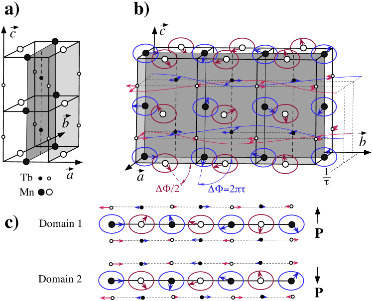
Bulk measurements first established that TbMnO3 undergoes a transition below =27 K to a multiferroic state that is both magnetic and FE, and demonstrated how a magnetic field could be used to control ferroelectricity Kimura et al. (2003). A major breakthrough in understanding this effect was provided by a neutron diffraction study which concluded that at =27 K the Mn magnetic moments undergo a transition from a collinear to a non-collinear, cycloidal phase, described by an incommensurate wavevector , which removes a centre of inversion so as to form a FE state Kenzelmann et al. (2005). For this class of multiferroic, the FE moment may be conveniently written as , where = characterises the magnetic structure adopted by the spins Katsura et al. (2005); Mostovoy (2006); Sergienko et al. (2006). In the case of TbMnO3 the Mn magnetic moments in the cycloidal phase rotate in the plane (Fig. 1), and with parallel to the axis, is either parallel or anti-parallel to the axis depending on the sign of . The same study Kenzelmann et al. (2005) proposed that the Tb moments are also sinusoidally modulated at , but are transversely polarized along the axis. Polarized neutron diffraction has recently been applied to multiferroics Radaelli et al. (2008); Lee et al. (2008), including TbMnO3 Yamasaki et al. (2007), where it was found that the cycloid could be switched from propagating clockwise or anticlockwise, depending on the direction of the applied electric field Yamasaki et al. (2007). Our non-resonant X-ray magnetic scattering (NRXMS) study of TbMnO3 establishes the utility of X-rays for studying the electric field control of magnetism in multiferroics. Although NRXMS experiments are in many ways much more demanding than neutron diffraction, due to the extreme weakness () of the NRXMS relative to the charge scattering, they are nontheless of considerable value due to the complementary nature of the information they provide. In the case of TbMnO3 this has allowed us to reveal the ordering of a component on the Tb sublattice and to determine various phase relationships that were hitherto unknown.
TbMnO3 adopts the space group at room temperature with Å, Å and Å Blasco et al. (2000). We selected a single crystal grown by the floating zone method, as used in previous resonant X-ray scattering experiments Mannix et al. (2007). The sample had dimensions mm3, and a poling electric field of about 1 kV/mm was applied during the cooling procedure inside a 4He evaporation cryostat. Two copper electrodes were glued by high conductive silver paste on the sample -surfaces, and the electric field was removed during the X-ray experiments.
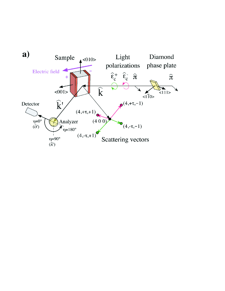
X-ray magnetic diffraction experiments were performed at the ID20 beamline Paolasini et al. (2007) (ESRF, Grenoble, France) using a monochromatic beam at a wavelength of =1.66 Å, so as to excite non-resonant processes, which allows the spin and orbital magnetizations to be determined independently Blume and Gibbs (1988). (Neutron scattering, by contrast, is sensitive to their sum.) Linearlly polarized X-rays were converted into left-circularly polarized (LCP) or right-circularly polarized (RCP) photons using a diamond quarter-wave plate (circular polarization typically ), or allowed to pass unchanged through the phase plate, see Fig. 2(a). For a cycloidal magnet, the incoming circular polarization finds its handedness naturally coupled to the sense of rotation of the magnet moments, allowing the population of domains to be determined by observing differences in the intensity of magnetic diffraction peaks under illumination with LCP or RCP X-rays. An Au (222) crystal analyzer system mounted on the detector arm of a six-circle diffractometer was used to characterise the polarization of the scattered photons. The polarization is represented by the Stokes vector P=(,,) de Bergevin and Brunel (1981); Blume and Gibbs (1988), whose linear components , were determined by fitting the dependence of the scattered X-ray intensity on the angle of the polarization analyzer about the wavevector . The Stokes parameters of the incident beam were carefully checked before and after every set of scans by using the same polarization analyzer, to control the incident circular photon polarization, which is very sensitive to the beam position stability.
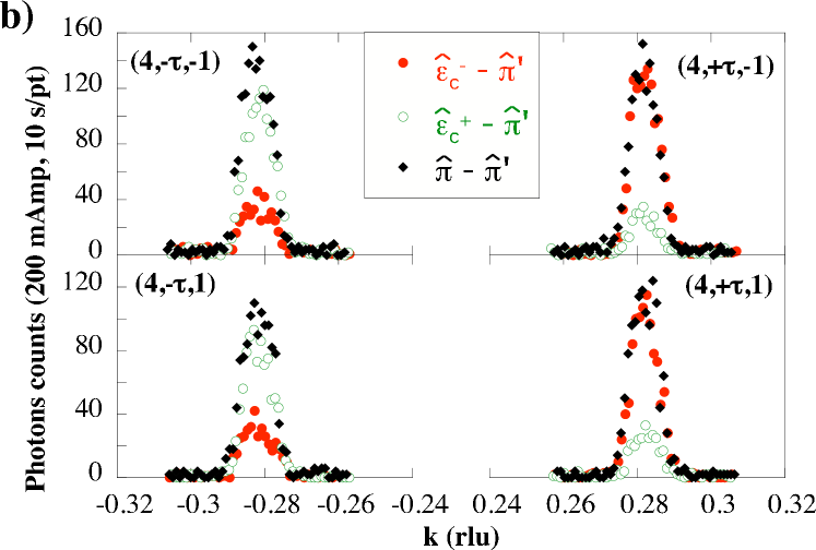
The initial objective of our study was to establish whether or not our experimental setup provided sufficient sensitivity to any imbalance in the population of magnetic domains produced by the applied field. Figure 2(b) shows the polarization dependence of the scattering from the four A-type Quezel et al. (1977) magnetic satellite reflections each satellite forming one arm of the so-called star of wavevectors around , see Fig. 2(a). The measurements were performed at 15 K in the FE phase, after cooling the sample with a poling voltage of 700 V. Data were collected with linear (, black diamonds), RCP (, open green circles), and LCP (, red filled circles) polarized X-rays, while the scattered beam was analyzed in the channel (). Inspection of Fig. 2(b) reveals that the intensities of the magnetic satellites are very similar when incident linear polarization is selected. For incident circular polarizations this is not the case: instead the intensities display complementary behaviour, depending on the sign of . In the case of equi-populated cycloidal domains the intensities associated with and should be similar, whereas for a single cycloidal domain a large difference is expected, as is indeed observed to be the case.
The standard approach to obtain a microscopic understanding of the field-induced magnetic domain state would be to collect intensity data for a set of satellites (,,) with taking on as wide a range of values as possible. The disadvantages of this method are that large corrections must be applied for effects such as absorption, etc., and that our specific scattering geometry restricts the accessible values. Instead we undertook a detailed analysis of the polarization of the scattered beam by carefully measuring for each of the satellites shown in Fig. 2(a), extracting the Stokes parameters. Figure 3 summarises our data for field-coolings performed with either or . The data were obtained by rocking the crystal analyzer at different angles, and are normalized by monitor and corrected by subtraction of the background, measured off peak.
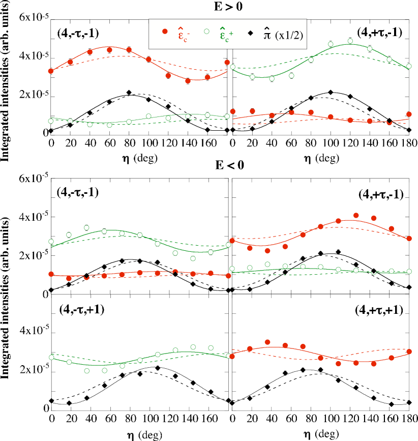
Turning first to consider the case of incident linear () polarization shown in Fig. 3, it is clear that for a particular choice of the direction of , only small differences in are observed for the various satellites, and that reversing the direction of does not appear to have any effect. Clear differences in of the various satellites are observed for incident circular polarization. In this case reversing the direction of has a profound effect on the observed intensities. For a given field direction, changing the sign of at fixed leads to a switching of the handedness of incident X-rays that produces the maximum intensity, whereas the handedness associated with the maximum satellite intensity is invariant with respect to changes in the sign of . Of considerable significance is the fact that reversing the sign of leads to a switching of the dominant handedness. Also apparent are clear mirror symmetries between LCP and RCP X-rays for the same reflection, and between satellites for the same incident polarization state. Thus at a qualitative level the data displayed in Fig. 3 reveal an imbalance in the population of the two possible magnetic domains created by the applied electric field, an imbalance that can be reversed by switching the direction of the field.
To explore the potential richness of information encoded in the data shown in Fig. 3 we performed extensive modelling of the magnetic scattering. For the initial model we used the structure due to Blasco et al. Blasco et al. (2000), as shown in Fig. 1(a), and the magnetic structure proposed by Kenzelmann et al. Kenzelmann et al. (2005), as shown in Fig. 1(b). In Fig. 3 the results of our calculations of NRXMS Blume and Gibbs (1988) based on this model are represented by dashed lines. For the calculations the exact scattering geometry of the six-circle setup was taken into account. The agreement between the model and the data is clearly unsatisfactory. In particular, the data show a non zero value of (a linear polarization oblique with respect to directions , ), that is not predicted by the model.
A vastly improved description of the data was achieved following the realisation that, in contrast to the earlier neutron diffraction study, our experiment yielded sensitivity to the component of the ordered moment on the Tb sites, while being largely insensitive to the component. From the fits we are able to fix the phase angle between the magnetic modulations of the Tb and the Mn atoms. Consider one Mn atom, and the subsequent Tb atom moving along (sign determined accordingly to the direction of the electric polarization), then the phase angle between their magnetic modulations, evaluated at the same coordinate in space, is found to be 1.0 0.1 (with reference to the components). The phase shift between the two orbits of Tb atoms (at and of the unit cell) is determined to be 1.0 0.2 .
The model results in the following NRXMS amplitude for an A-type peak of the form (4 1):
where the value of selects the sign of , the sign of and identifies the two cycloidal domains 1 and 2, respectively (Fig. 1(c)). The vectors and contain the dependence on the polarization of the incident and diffracted X-rays Blume and Gibbs (1988). The spin (K) and the orbital (K) magnetic components contain the form factors for Mn3+ and Tb3+ at a given scattering vector . We suppose also that the orbital contribution of Mn is quenched, and that of Tb equal to its spin moment () as follows from Hund’s rules for a electronic configuration. Finally describes the fractional atomic coordinate along the axis of the Wyckoff position (4c), for the Tb atoms Blasco et al. (2000).
A simplified expression for the NRXMS amplitude in the and channels, in which we set the scattering angle , and place the axis perpendicular to the scattering plane, illustrates the sensitivity in our experiment to the different components of the Tb and Mn magnetic moments, and the dependence of the scattered intensity on the handedness of the X-rays, etc:
Here selects the handedness of the incident X-rays, and , etc., are the projected magnetization densities on the incident (scattered) wavevector. The dominant Mn terms are real in and imaginary in , giving a scattered beam that is mainly circularly polarized. They are large (small) if . A non zero value of arises when the pair have different moduli. This depends on and . Their sign in () is to be compared to the sign of the largest term in (). Then it is seen that adds with opposite signs in the real and imaginary parts, so that its effect in nearly cancels. Instead produces a net with the sign .
The full expression Circularly polarised X-rays as a probe of non-collinear magnetic order in multiferroic TbMnO3 for was fitted to the data with the outcome represented by the solid lines in Fig. 3. It is clear that inclusion of a component of the Tb moment leads to an excellent description of the data, with the best fit obtained with ( + 2) equal to 1.0 0.3 . Most importantly, our refined model of the magnetic structure allows us to obtain an accurate description of the domain state in our sample as a function of applied electric field, including the absolute sense of rotation of the magnetic moments. We conclude that cooling in a positive electric field led to a population of 96(3)% of the cycloidal domain in which the transverse spiral of the Mn atoms is counterclockwise, when moving along and looking from (domain 1 in Fig. 1(c)), while field cooling in a negative electric field produced a population of 83(2)% for the domain of opposite sense of rotation (domain 2 in Fig. 1(c)).
Our results establish the benefits of performing NRXMS experiments when circularly polarized X-rays are combined with full polarization analysis of the scattered beam. Applied to cycloidal systems this technique is capable of providing a quantitative, microscopic description of the cycloidal domain state. For the specific case of multiferroic TbMnO3, with two different types of magnetic ion, making it by any standards a challenging test case, we have shown surprisingly that this approach allows us to make important refinements to the magnetic structure obtained from neutron diffraction. This technique could readily be applied to other multiferroics, particularly those such as BiFeO3 Teague et al. (1970); Sosnowska et al. (1982) for which open questions remain concerning the magnetic structure of bulk samples and its modification in thin films Wang et al. (2003); Ederer and Spaldin (2005); Zhao et al. (2006); Lee et al. (2008).
Acknowledgements.
We wish to acknowledge Andrea Fondacaro for technical support at ID20.References
- Fiebig (2005) M. Fiebig, J. Phys. D: Applied Physics 38, R123 (2005).
- Kimura et al. (2003) T. Kimura et al., Nature 426, 55 (2003).
- Kenzelmann et al. (2005) M. Kenzelmann et al., Phys. Rev. Lett 95, 087206 (2005).
- Eerenstein et al. (2006) W. Eerenstein, N. D. Mathur, and J. F. Scott, Nature 442, 759 (2006).
- Cheong and Mostovoy (2007) S.-W. Cheong and M. Mostovoy, Nat. Mat. 6, 13 (2007).
- Erskine and Stern (1975) J. Erskine and E. Stern, Phys. Rev. B 12, 5016 (1975).
- van der Laan et al. (1986) G. van der Laan et al., Phys. Rev. B 34, 6529 (1986).
- Schütz et al. (1987) G. Schütz et al., Phys. Rev. Lett. 58, 737 (1987).
- Sutter et al. (1997) C. Sutter et al., Phys. Rev. B 55, 954 (1997).
- Durr et al. (1999) H. A. Durr et al., Science 284, 2166 (1999).
- Paolasini and de Bergevin (2008) L. Paolasini and F. de Bergevin, C. R. Phys. 9, 550 (2008).
- Katsura et al. (2005) H. Katsura, N. Nagaosa, and A. V. Balatsky, Phys. Rev. Lett. 95, 057205 (2005).
- Mostovoy (2006) M. Mostovoy, Phys. Rev. Lett. 96, 067601 (2006).
- Sergienko et al. (2006) I. A. Sergienko, C. Şen, and E. Dagotto, Phys. Rev. Lett. 97, 227204 (2006).
- Radaelli et al. (2008) P. G. Radaelli et al., Phys. Rev. Lett. 101, 067205 (2008).
- Lee et al. (2008) S. Lee et al., Phys. Rev. B 78, 100101(R) (2008).
- Yamasaki et al. (2007) Y. Yamasaki et al., Phys. Rev. Lett. 98, 147204 (2007).
- Blasco et al. (2000) J. Blasco et al., Phys. Rev. B 62, 5609 (2000).
- Mannix et al. (2007) D. Mannix et al., Phys. Rev. B 76, 184420 (2007).
- Paolasini et al. (2007) L. Paolasini et al., J. Synch. Rad. 14, 301 (2007).
- Blume and Gibbs (1988) M. Blume and D. Gibbs, Phys. Rev. B 37, 1779 (1988).
- de Bergevin and Brunel (1981) F. de Bergevin and M. Brunel, Acta Cryst. A37, 314 (1981).
- Quezel et al. (1977) S. Quezel et al., Physica B+C 86-88, 916 (1977).
- Teague et al. (1970) J. R. Teague, R. Gerson, and W. J. James, Solid State Comm. 8, 1073 (1970).
- Sosnowska et al. (1982) I. Sosnowska, T. P. Neumaier, and E. Steichele, J. Phys. C: Solid State Phys. 15, 4835 (1982).
- Wang et al. (2003) J. Wang et al., Science 299, 1719 (2003).
- Ederer and Spaldin (2005) C. Ederer and N. A. Spaldin, Phys. Rev. B 71, 224103 (2005).
- Zhao et al. (2006) T. Zhao et al., Nat. Mat. 5, 823 (2006).