Growth rate and the cutoff wavelength of the Darrieus-Landau instability in laser ablation
Abstract
The main characteristics of the linear Darrieus-Landau instability in the laser ablation flow are investigated. The dispersion relation of the instability is found numerically as a solution to an eigenvalue stability problem, taking into account the continuous structure of the flow. The results are compared to the classical Darrieus-Landau instability of a usual slow flame. The difference between the two cases is due to the specific features of laser ablation: high plasma compression and strong temperature dependence of electron thermal conduction. It is demonstrated that the Darrieus-Landau instability in laser ablation is much stronger than in the classical case. In particular, the maximum growth rate in the case of laser ablation is about three times larger than that for slow flames. The characteristic length scale of the Darrieus-Landau instability in the ablation flow is comparable to the total distance from the ablation zone to the critical zone of laser light absorption. The possibility of experimental observations of the Darrieus-Landau instability in laser ablation is discussed.
I Introduction
Inertial confinement fusion (ICF) is believed to be one of the promising energy sources in the 21st century. The aim of ICF is to compress a plasma target to densities and temperatures high enough to trigger a thermonuclear reaction. Despite a great technical development and progress in power supplies during the last decades Dunne-06 , hydrodynamic instabilities remain the limiting factor in fusion performance and efficiency. In this respect, the most difficult obstacle in achieving ICF is the Rayleigh-Taylor (RT) instability, which arises because of target acceleration Eliezer ; Bodner ; Kull-91 ; Bychkov-94 ; Betti-95 ; Betti-06 ; Sanz et al. ; Bychkov_RTI_ICF-07 . Still, the RT instability is not the only instability of importance in ICF; for example, the laser generated plasma is also subject to the so called Darrieus-Landau (DL) instability Bychkov-94 ; Piriz-01 ; Piriz-03 ; Keskinen et al. ; Gotchev et al. ; Goncharov et al. ; Modestov_RTI ; Clavin-04 ; Bychkov-08 . Traditionally, the DL instability is known as the hydrodynamic instability of a slow flame LandauL ; Zeldovich ; review ; Searby and Clavin , which makes the flame front corrugated and increases the burning rate. Flame is the most typical example of a deflagration wave, which is a front propagating due to energy release and thermal conduction. The ablation flow generated by laser radiation on a plasma target is also a deflagration wave Manheimer ; Fabbro ; Bychkov_RTI_ICF-07 . Other interesting examples of deflagration come from astrophysical applications like the big bang model and type I supernovae Link-92 ; Kamionkowski-Freese-92 ; Fragile-Anninos-03 ; Bychkov_Astron-95 ; Gamezo et al.2003 ; Bychkov_AstRep-06 . On the basis of similar physical properties of deflagrations, one should expect the DL instability to develop in laser ablation. There has been much interest in the DL instability in ablation flows, see e.g. Refs. Bychkov-94 ; Piriz-01 ; Piriz-03 ; Keskinen et al. ; Gotchev et al. ; Goncharov et al. ; Modestov_RTI ; Clavin-04 ; Bychkov-08 . However, the most important features of the instability has remained unclear up until now. The purpose of the present theoretical work is to answer some of the key questions concerning the DL instability in laser ablation and to indicate conditions for experimental observation of the instability.
The classical theory of the DL instability considers an incompressible flow generated by a slow flame LandauL ; Zeldovich ; review ; Searby and Clavin . However, the parameters of laser ablation flows in ICF are markedly different from those of slow combustion. One of the most distinctive features of deflagration in ICF is that the plasma velocity reaches the isothermal sound speed at the critical surface of laser light absorption. For this reason, laser ablation corresponds to the so-called Chapman-Jouguet (CJ) deflagration, which is the fastest propagation regime possible for a deflagration front. Thus, in order to describe the DL instability in laser ablation one has to take into account strong compression of the plasma flow with relatively high local values of the Mach number. Another important property inherent to the plasma flow is the strong temperature dependence of electron thermal conduction. Electron thermal conduction determines the total thickness and the internal structure of laser deflagration. It is expected that the strong plasma compression and the electron thermal conduction properties will significantly influence the properties of the DL instability in a laser generated plasma, making it markedly different from the case of slow flames. A number of papers was devoted to the linear and nonlinear stages of the DL instability in ICF Piriz-03 ; Clavin-04 ; Sanz et al. ; Bychkov-08 ; Keskinen et al. ; Gotchev et al. ; Goncharov et al. . Still, these papers did not answer the most important questions concerning the DL instability in laser ablation. In particular, we would here like to outline the following three questions within the problem:
-
1.
How strong is the DL instability in laser ablation in comparison to the classical case, i.e., is it stronger or weaker than the DL instability developing at a slow flame front?
-
2.
What is the characteristic length scale of the instability development? This question is especially important from the experimental point of view, since the answer determines the target size, for which the DL instability may be observed.
-
3.
What is the outcome of the DL instability at the nonlinear stage?
There have been numerous attempts to answer the first question within the model of a discontinuous deflagration front in a compressible gas/plasma flow Kadowaki ; He ; Piriz-03 ; Piriz-01 ; Bychkov-08 . Unfortunately, the discontinuous model encounters the deficit of matching conditions at the deflagration front; the number of unknown variables exceeds the number of conservation laws at the front by one. The problem was encountered first within the studies of the RT instability in laser ablation, see Refs. Bodner ; Bychkov-94 ; Bychkov_RTI_ICF-07 ; more detailed discussion on this subject may be found in Ref. Bychkov-08 . In the classical incompressible limit of the DL instability at a slow flame front, the extra condition is given by the so-called DL condition of a constant deflagration speed with respect to the cold gas. This condition may be proven rigorously, see Ref. Searby and Clavin ; review . A counterpart of the DL condition for a compressible flow is not obvious and the solution to the problem turned out to be sensitive to this assumed extra condition, so that the different analytical theories proposed led to qualitatively different results. For this reason, it was unclear if strong plasma compression in laser ablation made the DL instability stronger, or weaker, or only produces minor changes in the instability strength. Within this context, Refs. Travnikov-97 ; Travnikov-99 deserve special attention, since these papers considered influence of gas compression on the DL instability taking into account a continuous structure of the deflagration front. Though Refs. Travnikov-97 ; Travnikov-99 were devoted to normal combustion, and the respective results cannot be extrapolated directly to the DL instability in laser ablation, the method used in these papers may still be used for the ablation studies. This method eliminates the deficit of boundary conditions and allows for investigating the properties of the DL instability in laser ablation. Here we employ the methods of Refs. Travnikov-97 ; Travnikov-99 to study the linear stage of the DL instability in a laser plasma, thus answering questions 1 and 2 of those outlined above.
In the present paper we investigate main characteristics of the linear DL instability in the laser ablation flow. We find the dispersion relation of the instability numerically as a solution to an eigenvalue stability problem taking into account the continuous structure of the flow. We compare the results to the classical DL instability of a usual slow flame. We show that difference between the two cases is due to two specific features of laser ablation: a high plasma compression and a strong temperature dependence of the electron thermal conduction. We further demonstrate that the DL instability in laser ablation is much stronger than in the classical case. In particular, the maximal growth rate of perturbations in laser ablation is about three times larger than for slow flames. The characteristic length scale of the DL instability in the ablation flow is comparable to the total distance from the ablation zone to the critical zone of laser light absorption. We discuss the possibility of experimental observations of the DL instability in laser ablation.
II Basic equations and the stationary solution
We describe the ablation plasma flow using hydrodynamic equations of mass, momentum and energy conservation
| (1) |
| (2) |
| (3) |
and the equation of state of an ideal gas
| (4) |
where is the adiabatic exponent, and are the heat capacities at constant pressure and volume respectively. Electron thermal conduction depends on temperature as , where label “c” refers to the critical surface of laser light absorption. Laser light absorption brings energy into the plasma and, together with thermal conduction, it drives the flow. Absorption takes place when plasma frequency is equal to the laser frequency
| (5) |
which determines plasma density at the critical surface (here is plasma mass per one electron). Decrease of the laser light intensity due to absorption may be described as Eliezer
| (6) |
with the absorption coefficient
| (7) |
The absorption coefficient diverges at the critical surface, and, therefore, the process of energy absorption is strongly localized at the surface. In the studies of ablation flow and the RT and DL instabilities in the flow, the energy release is typically presented by -function Bodner ; Manheimer ; Bychkov-94 ; Piriz-01 ; Piriz-03 . Such replacement is possible since the instabilities develop on the length scales much larger than the region of energy release and involve bending of this region as a whole without changing its internal structure. In the present paper we solve the problem of the DL instability numerically. In the numerical solution, it is more convenient to imitate the -function by a transitional zone of finite width determined by some continuous function of energy gain in the flow included into Eq. (3). Here, we chose the function in the form suggested in Ref. Bychkov-08
| (8) |
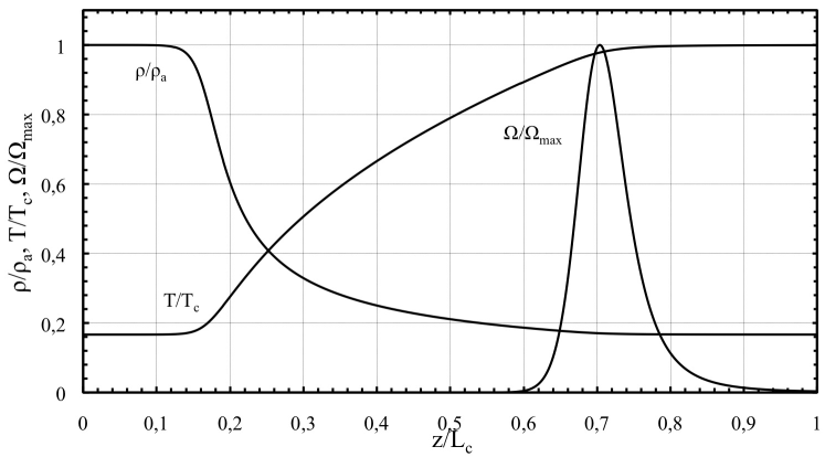
The function was constructed taken into account similarity with the Arrhenius law in combustion, where plays the role of the scaled activation energy and is similar to the reaction order. It is well-known that the Arrhenius law provides strong localization of energy release for any reasonable in the case of sufficiently large , see Zeldovich ; review . In combustion science the Arrhenius reaction is sensitive to temperature changes Zeldovich ; review . Here we construct the function of energy gain sensitive to density variations, as it takes place in laser ablation. Choosing large parameter we obtain energy gain strongly localized at the critical surface with . On the other hand, the numerical solution demands a finite width of the zone of energy release and the finite value of the parameter . In most of our calculations we use , . We also investigate sensitivity of the physical results to the choice of these parameters. We demonstrate that these parameters have minor influence upon the properties of the DL instability and at high values of this influence vanishes. The function given by Eq. (8) allows a planar stationary solution consisting of two uniform flows of cold heavy plasma (label “a”) and hot light plasma (label “c”) separated by a transitional region, which is the deflagration front. The labels “a” and “c” originate from the ablation and critical surfaces in the laser deflagration. Typical internal structure of the deflagration front is illustrated in Fig. 1. The described geometry is common in the theoretical studies of the RT and DL instabilities of the ablation flow Bodner ; Bychkov-94 ; Piriz-01 ; Piriz-03 ; He ; Betti-95 ; Kull-91 ; Sanz et al. ; Bychkov_RTI_ICF-07 , though it does not take into account the rarefaction wave in the hot light plasma beyond the critical surface. As the main advantage of such a choice, we may consider different values of the Mach number in the light plasma, which would be impossible with a rarefaction wave. Changing the Mach number, we can go over continuously from the case of classical incompressible DL instability of a usual flame front to the case of laser ablation with strong influence of plasma compression. We stress that the main purpose of the present paper is to compare the DL instability in laser ablation to the classical case. Therefore, in general, we will discuss stability of a deflagration front, which covers the cases of usual flames (slow combustion) and laser ablation as two asymptotic limits of negligible compression effects and ultimately strong plasma compression.
We start our analysis with describing internal structure of the stationary planar deflagration (laser ablation) flow; this is the first step in the stability analysis. Figure 1 illustrates plasma density, temperature and energy release in the flow obtained numerically as described below. The deflagration front in Fig. 1 propagates to the left with constant velocity (the ablation velocity) in the negative direction of z-axis. Velocity of a usual flame is determined by the rate of energy release and thermal conduction. Ablation velocity is determined by the critical density and the laser light intensity Manheimer . We adopt the reference frame of the deflagration front. In that case the front is at rest, but the cold heavy plasma flows to the right with uniform velocity , undergoes transition in density and temperature in the deflagration wave, and, finally, the hot light plasma gets drifted away with uniform velocity .
Equations of mass and momentum transfer (1), (2) may be integrated for the planar stationary deflagration as
| (9) |
| (10) |
One of the main dimensionless parameters in the problem is the expansion factor
| (11) |
which shows density drop from the original cold plasma to the critical surface. Both in flames and laser ablation, the expansion factor is rather large, , see review ; Betti-06 . In the case of ablation flow, the laser light frequency determines the critical density and the expansion factor. The other important parameter is the Mach number in the light plasma (gas) corresponding to the adiabatic sound
| (12) |
The Mach number is negligible in the classical case of usual flames, and it may be taken zero with a very good accuracy. On the contrary, laser ablation provides an ultimately large value of the Mach number possible for a deflagration flow. In laser ablation, the isothermal Mach number is equal unity in the light plasma, and we have for the adiabatic Mach number. In the present work we consider a general case of a deflagration front with an arbitrary Mach number changing within the limits . The internal structure of the deflagration front follows from the stationary equation of energy transfer
| (13) |
Characteristic width of the front is determined by thermal conduction in the hot region
| (14) |
The problem involves one more parameter of length dimension
| (15) |
related to thermal conduction in the cold flow. Because of the strong temperature dependence of electron thermal conduction, these two length scales are quite different . For example, for the temperatures ratio , the length scales differ by two orders of magnitude . The strong difference in these length scales is one of the specific features of laser ablation in comparison with usual flames.
We introduce dimensionless variables for plasma density, temperature, velocity and coordinate
| (16) |
Then we can rewrite Eq. (13) as
| (17) |
where is an eigenvalue of the stationary problem. The relation between temperature and density in a deflagration flow follows from Eqs. (9), (10)
| (18) |
In the incompressible limit of usual flames, , this relation is reduced simply to , so that temperature ratio is determined by the expansion ratio, . In the case of strong gas compression, these two values differ considerably. For example, in the case of laser ablation with the critical Mach number , we find from Eq. (18) that
| (19) |
For high values of density drop, , temperature ratio is about twice smaller than the expansion factor, . Because of the reduced temperature ratio, the effect of two different length scales Eqs. (14), (15) in the ablation flow is expected to become weaker than in a similar incompressible flow. With temperature ratio changing from in the incompressible case to in the ablation flow we find the ratio of length scales decreasing by the factor of . For this reason, the profiles of density and temperature are expected to be much smoother in the ablation flow in comparison with an incompressible counterpart.
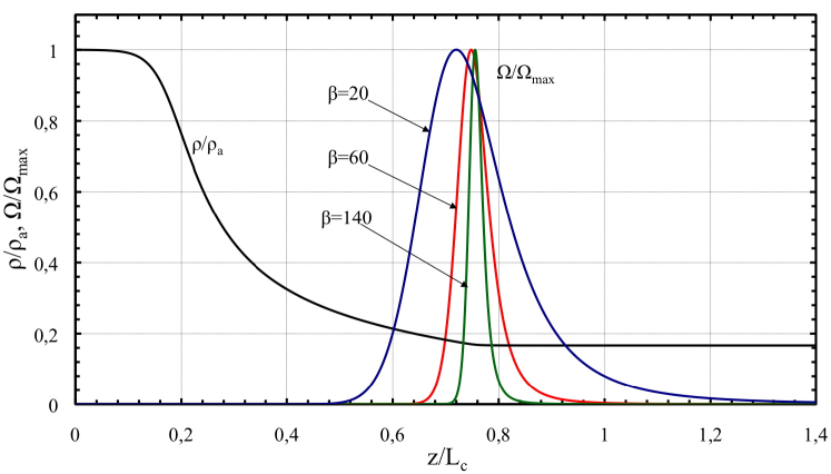
We solve Eq.(17) together with Eq. (18) numerically for different values of the Mach number. Typical solution to the problem for incompressible case is shown in Fig. 1. First of all, we have to make sure, that the ablation front structure is not sensitive to our choice of the energy gain function . We investigate dependence of the density and temperature profiles on the parameter . Figure 2 shows density and energy release for , , , . Density profiles for these three values of coincide almost everywhere except for the zone of energy gain. Still, even inside this zone, the difference between the density profiles is minimal, and cannot be recognized on Fig. 2. Similar result holds for the temperature profiles. Thus, we can conclude that parameter does not affect the density and temperature profiles in the ablation front. At the same time, parameter influences strongly the profile of energy release itself: the respective plots become much more localized with increasing. Thickness of the critical surface should be zero in the hydrodynamic description of the ablation flow. Therefore, finite width of the zone of energy gain implies certain inaccuracy of the numerical solution. The level of inaccuracy of the model may be evaluated as the characteristic width of the energy gain zone in the dimensionless variables (scaled by the total thickness of the deflagration front . As we can see in Fig. 2, half width of the energy peak is rather wide for ; it takes more than 20% of the whole deflagration front. As we increase , this width becomes smaller and for the inaccuracy is less than 5% . The other parameter of the energy gain function in Eq. (8), , affects the shape of the energy release peak only slightly even for moderate values of . For the parameter has a negligible effect on the physical results. Thus, Eq. (8) may imitate the energy gain in the ablation flow quite well; in all following numerical solutions and figures and .
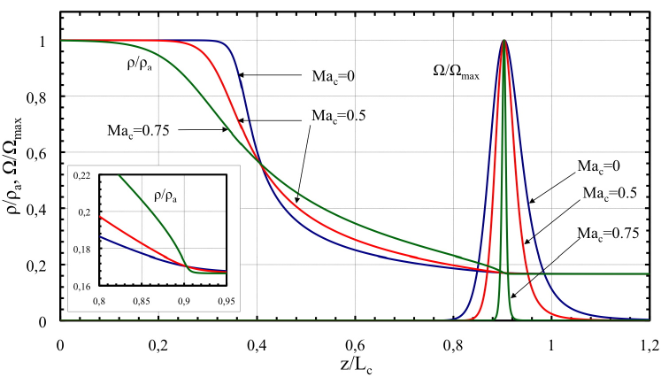
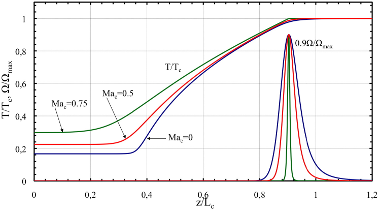
As the next step, we solve Eq. (17) for different values of the Mach number. Figure 3 shows profiles of density and energy release, for , other parameters being fixed as , , ; Figure 4 presents the respective temperature profiles. In the case of incompressible flow, , the density profile demonstrates clearly the effect of two length scales, Eqs. (14), (15), produced by the temperature-dependent thermal conduction. The profile is rather smooth in the hot region close to the critical surface, and it becomes sharp in the cold plasma close to the ablation surface with large density gradient. In fact, it is this property, which allows distinguishing two effective surfaces in the flow: the ablation and critical surfaces Manheimer ; Piriz-01 ; Bychkov-94 . In the case of strong compression with , the density profile becomes much smoother. Smoothing of the density profile concerns the region of cold plasma mainly. Another specific feature of the density profile at high values of the Mach number is shown at the insert of Fig. 3. With the Mach number approaching the maximal possible value , we observe development of another mini-region of relatively high density gradient close to the critical surface. This effect may be also obtained analytically from Eq. (18). Close to the critical surface, expanding density and temperature in power series with respect to , , we obtain the relation , or in the dimensional values. Taking energy gain in the form of -function, we have temperature achieving the final value at finite point smoothly. This leads to the square-root singularity in the density gradient. We can observe the trace of such a singularity in the insert of Fig. 3, though smoothed because of the finite width of the energy gain zone. We also observe changing shape of the energy gain with Mach number. The energy gain zone becomes much thinner at high values of the Mach number. This happens because the energy release Eq. (8) is sensitive to the density profiles. Sharp gradients of density at make the zone of energy gain sharper as well. As a result, the model Eq. (8) works much better at high values of the Mach number corresponding to the laser ablation flow. Figure 4 demonstrates that temperature profiles become also smoother with increasing Mach number, which is similar to density profiles. Besides, temperature ratio at the ablation and critical surfaces decreases with increasing the Mach number, as we demonstrated in Eqs. (18), (19). The numerical solution for the planar stationary flow illustrated in Figs. 1-4 provides the basis for the stability analysis performed in the next section.
III Linearized equations
We solve the stability problem for small perturbations of any value in the form:
| (20) |
where the first term in the right-hand side of (20) stands for the stationary flow, the second term describes linear perturbations, is the instability growth rate and is the perturbation wave number. In general, may have both a real part (growth rate) and an imaginary part (frequency). However, in the case of the DL instability is only real; the instability develops when is positive.
The linearized system (1-3) takes the form
| (21) |
| (22) |
| (23) |
| (24) |
Similar to Bychkov-94 , we introduce the dimensionless perturbations of mass flow , transverse velocity , temperature and dynamic pressure as
| (25) |
with the scaled wave number and the perturbation growth rate
| (26) |
| (27) |
| (28) |
| (29) |
| (30) |
where and the coefficients in Eq. (30) are
| (31) |
| (32) |
| (33) |
| (34) |
| (35) |
As the boundary conditions to the system (27)-(30), we demand that perturbations vanish at infinity in the uniform flows of cold plasma ahead of the ablation zone and the hot plasma behind the critical zone of energy gain. The coefficients in Eqs. (27)-(30) are constant in the uniform flows. This allows us writing down the perturbations in an exponential form , where in the heavy plasma ( and in the light plasma . In some particular simplified limits the structure of the perturbation modes in the uniform flows may be written analytically, e.g. see Bychkov-08 . However, in the present case we can do it only numerically, which becomes another step in the numerical solution to the problem.
IV The algorithm for the numerical solution
The derived system (27)-(30) is rather complicated and it may be solved only numerically. We introduce an auxiliary variable to obtain two differential equations of the first order instead of Eq. (30) as
| (36) |
| (37) |
Thus we have a system of five differential equations of the first order with the scaled growth rate as an eigenvalue. The purpose of the solution is to find the dispersion relation . The system may be written in a matrix form
| (38) |
where is a vector of the perturbations and is the matrix
| (39) |
The numerical solution consists of the following steps. First we look for the density profile in the stationary solution to Eq. (17). Equation (17) is integrated numerically from the uniform flows of cold and hot plasma to the central parts of the deflagration transitional region. Both solutions are matched at a certain density value; we checked that the physical results do not depend on the choice of the matching point. When density distribution is known, temperature and velocity profiles are determined using Eqs. (9) and (18). The respective numerical problem involves several length scales, which creates an additional difficulty in the solution. In the case of highly compressible flow the peak of energy release is extremely sharp; but we have to resolve it properly, since it is used afterwards in the solution to the stability problem. As the next step, we find modes in the uniform flows, which determine the boundary conditions for Eqs. (27) – (29). In the uniform flows, Eq. (38) is a system of linear ordinary equations with constant coefficients. In order to find the factors , we solve
| (40) |
where is the unit matrix. Thus we obtain an equation for in the form of a polynomial of the fifth order. In the incompressible case this equation may be solved analytically. Five different roots correspond to the vorticity mode, two sound modes and two modes of thermal conduction and/or energy gain Liberman-94 ; Bychkov-94 ; Bychkov-08 . Solving Eq. (40) numerically we find five modes with two positive and three negative values taking for and for . Finally, we integrate the system (38) numerically in the transitional region of the deflagration flow. We perform the numerical integration two times from the right-hind side and three times from the left-hand side with boundary conditions determined by different modes. We match these five solutions at a certain point between the maximum of the energy release and the ablation zone of sharp density gradients. Again, the physical results do not depend on the choice of the matching point. Then we obtain a matrix consisting of twenty five values describing flow perturbations for five modes. Taking the determinant of this matrix equal zero, we find the dispersion relation.
V Results and discussion
Before presenting the numerical solution to the stability problem, we explain the physical results we are looking for. In the classical case of an infinitely thin flame front propagating in an incompressible flow, the instability growth rate was obtained by Darrieus and Landau LandauL ; Zeldovich as
| (41) |
where the coefficient depends on the expansion factor only
| (42) |
Traditionally the DL instability growth rate is scaled by the front velocity instead of used as the velocity unit in Secs. II, III. Here we follow the tradition and use for scaling when presenting the results. The approach of an infinitely thin front of the classical solution holds for long wavelength perturbations . Taking into account gas compression, we should expect the dispersion relation for an infinitely thin deflagration front in the same form as Eq. (41), but with the coefficient depending on the Mach number, . More general solution to the stability problem takes into account finite thickness of the deflagration front. Finite thickness of the deflagration front leads to stabilization of the DL instability at sufficiently short wavelengths. In the case of usual slow flames of finite thickness, the analytical solution to the problem may be found e.g. in Searby and Clavin . Written in the form of Taylor expansion in relatively small perturbation wave number, , the solution may be presented as
| (43) |
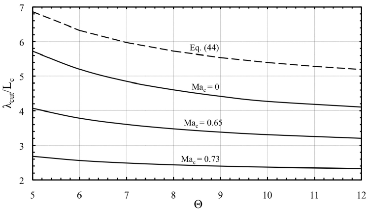
where is the cut-off wave number, is the cut-off wavelength. The approximation of the small cut-off wave number holds with reasonable accuracy for usual flames, e.g. see the review review . The cut-off wavelength is proportional to the thickness of the deflagration front, . In the incompressible flow, the coefficient of proportionality depends on the expansion factor and on the type of thermal conduction. Particularly, in the case of and an incompressible flow, the theory Searby and Clavin predicts
| (44) |
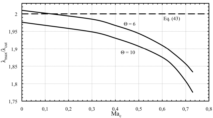
For typical expansion factors , Eq. (44) predicts the cut-off wavelength . For comparison, the DL cut-off for usual flames is considerably larger, being about , see review . According to the dispersion relation (43), there is a maximum of the instability growth rate achieved at a certain finite perturbation wavelength . Equation (43) predicts the wavelength of the maximum to be twice larger than the cut-off wavelength, . Taking into account gas compression, one should expect that all these values depend on the Mach number, . Therefore, the purpose of the present work is to investigate dependence of the parameters , , , on the Mach number changing within the interval . We demonstrate below that this dependence is quite strong.
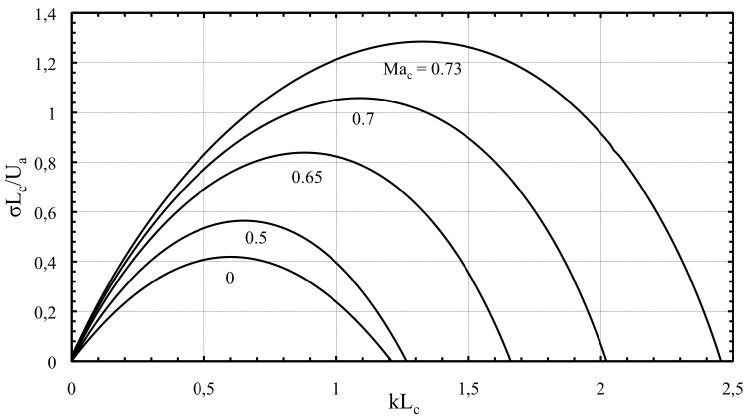
Figure 5 presents our numerical solution to Eqs. (27)-(30), that is the scaled instability growth rate versus the perturbation wave number. The dispersion relation is shown for different values of the Mach number, , with the expansion factor and a strongly localized energy release for , , see Sec. II. As we can see, the DL instability becomes much stronger with increasing the Mach number; plasma (gas) compression provides a strong destabilizing effect. This result looks very similar to one obtained for a flame in a compressible flame in Refs. Travnikov-97 ; Travnikov-99 . The destabilization concerns all parameters of the instability: the factor in Eq.(41), the maximal instability growth rate, , and the cut-off wave number, . These results are presented in Figs. 6 – 8, respectively. Figure 6 shows the factor , which determines strength of the DL instability in the case of an infinitely thin front. The solution is obtained for the expansion factors . According to Fig. 6, the DL instability for an infinitely thin ablation front (with ultimately strong plasma compression) is almost twice stronger than in the incompressible flow. The ratio of -factors obtained for and is about 1.8 for . Some analytical theories for the DL instability in compressible flows predicted also increase of the growth rate with the Mach number Kadowaki ; He . Still, the numerical results show a noticeably stronger increase than any analytical theory proposed so far. As explained in Bychkov-08 , the stability problem of a discontinuous deflagration front encounters a deficit of matching conditions at the front: the number of unknown values exceeds the number of matching equations by one. In order to overcome the obstacle, different additional matching conditions were suggested in different papers Kadowaki ; He ; Piriz-01 ; Piriz-03 ; Bychkov-08 . Solution to the problem turned to be quite sensitive to the choice of the extra condition; but the extra conditions suggested were merely assumptions. This trouble does not happen in the numerical solution, since the numerical solution considers continuous transition from heavy cold plasma to light hot one. For this reason, the numerical solution provides also a test for the suggested analytical solutions. In this work we are not going to criticize the previous analytical theories. Instead, we will try to extract the best ideas suggested so far in the theoretical papers Kadowaki ; He ; Piriz-01 ; Piriz-03 ; Bychkov-08 to obtain the analytical solution reasonably close to the numerical one. For that purpose we take the basic elements in the analysis Bychkov-08 and complement them by an extra matching condition identical to that of the DL theory of the incompressible flow LandauL . In the dimensional variables the DL matching condition is
| (45) |
where is perturbation of the discontinuous front position. The same type of matching condition was assumed for the DL instability in a compressible deflagration/ablation flow in Kadowaki ; Piriz-01 ; Piriz-03 . Reproducing calculations of Bychkov-08 with the extra condition (45) we obtain the following equation for
| (46) |
where
| (47) |
and the Mach number in the cold plasma
| (48) |
Influence of the Mach number may be illustrated in the limit of small plasma compression, , using Taylor expansion of Eq. (46). In that case
| (49) |
where corresponds to DL solution for incompressible case and is determined as
| (50) |
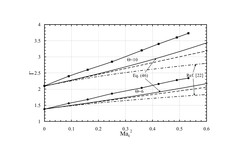
Positive factor indicates increase of the instability growth rate with plasma compression. The numerical solution to Eq. (46) together with Eq. (49) are presented in Fig. 6 by the solid and dashed lines respectively. These lines do not provide a perfect agreement with the numerical results; still the difference between the theory and the numerical solution is acceptable, about 15% . For comparison, Fig. 6 shows also the instability growth rate predicted in Kadowaki , by dash-dotted lines. The theory in Kadowaki differs much stronger from the numerical solution, approximately by 35% .
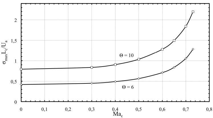
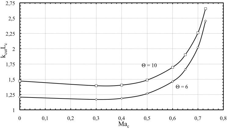
Figure 7 shows the maximal instability growth rate versus the Mach number for the expansion factors . As we can see, in the case of laser ablation with the maximal instability growth rate is about three times larger than in the incompressible case. These results agree well with the previous numerical calculations of Ref. Travnikov-97 for flames in a compressible flow. It is interesting that the maximal growth rate shows only minor dependence on the Mach number for a rather wide range of this parameter, . The strong dependence of on takes place only when the Mach number starts approaching the limiting value inherent to laser ablation. We observe a similar tendency in Fig. 8, which presents the cut-off wave number versus the Mach number. Again, the cut-off wave number is about twice larger for laser ablation in comparison with the incompressible case of zero Mach number. Figure 9 compares the cut-off wavelength found numerically for different values of the Mach number to the theoretical prediction Eq. (44). We remind that Eq. (44) follows from the theory Searby and Clavin in the limit of an incompressible flow and thermal conduction depending on temperature as . As we can see, the theory (44) provides a reasonable prediction for the cut-off wavelength in the case of zero Mach number; the difference between the theory and the numerical solution is about (15-25)% . As we increase the Mach number, the DL instability becomes stronger and the cut-off wavelength decreases considerably. For example, taking the expansion ratio we find the cut-off wavelength for laser ablation, for the incompressible case of and predicted by the analytical formula (44). Thus, the numerical solution predicts the DL instability in laser ablation on the length scales larger by the factor of 2.4 than the distance from the ablation zone to the critical zone. These length scales are very small when compared to the respective ratio for usual flames. However, these length scales are extremely large in comparison with the length scales typical for the RT instability in inertial confined fusion Bychkov-94 ; Betti-95 ; Sanz et al. . For this reason, in order to observe the DL instability experimentally one has to take special precautions eliminating the RT instability in the flow. One of the possible options is to use a sufficiently large target of the thickness exceeding the distance at least by an order of magnitude. In that case target acceleration is minor, which leads to the negligible RT instability, while the DL instability has sufficient space to develop. In addition, one has to remember that experimental observations typically concern the fastest growing perturbations of the wavelength and larger, not the cut-off wavelength . In the case of usual flames these two length scales are related as , since the whole dispersion relation may be described with a good accuracy by two first terms in Taylor expansion in , see Eq. (43). The ratio becomes somewhat different for the DL instability in laser ablation. Figure 10 shows the ratio obtained numerically for different values of the Mach number, and compares it to the classical case of . We can see that the wavelength corresponding to the maximal instability growth rate is about in laser ablation. The deviation indicates that next order terms become important in the Taylor expansion of the instability growth rate in . Still, the deviation is not too large.
Finally, we have to check that our model for the energy gain in the deflagration/laser ablation flow does not influence the physical results obtained. In order to validate the model we investigated influence of the parameters and of the energy gain on the DL dispersion relation. Numerical calculations for and different values of show negligible variations of all parameters of the instability: the -factor, the maximal instability growth rate and the cut-off wavelength. We also took and varied within the limits between 20 and 140. For example, taking we find the maximal growth rate for , for and for . These calculations indicate that the continuous numerical model for the energy gain function in Eq. (8) brings inaccuracy of only few per cent, about 3% , into the numerical solution for used in the present paper. Investigation of the cut-off wavelength for different and leads to similar conclusions.
VI Conclusions
In the present paper we investigated the DL instability in an ablation flow and compared the results to the classical case of a slow flame. Unlike the normal flame, laser ablation is characterized by the strongest plasma compression possible for a deflagration wave. Another specific feature of laser ablation is the strong dependence of electron thermal conduction on temperature. We demonstrate that the DL instability in laser ablation is much stronger than in the classical case. In particular, the maximal growth rate in the ablation flow is about three times larger than in the incompressible case. Moreover, the cut-off wavelength changes drastically as we go from the classical case of an incompressible flow to the ablation flow. The cut-off wavelength is also strongly influenced by the temperature dependence of thermal conduction. It is known that the DL instability for usual flames develops on quite large length scales exceeding the flame thickness by almost two orders of magnitude review . In contrast to this, the characteristic length scale of the DL instability in the ablation flow (e.g., the cut-off wavelength) is comparable to the total distance from the ablation zone to the critical zone of laser light absorption, . Still, even these values are large from the point of view of possible experimental observations of the DL instability in laser ablation. We note that the RT instability in inertial confined fusion develops on length scales much smaller than . For this reason, the DL instability may be observed only if the accompanied RT instability is suppressed. This may be achieved, for example, for sufficiently large targets of thickness much larger than the distance from the critical to the ablation zone.
Acknowledgements
This work was supported by the Swedish Research council and by the Kempe foundation.
References
- (1) M. Dunne, Nature Phys. 2, 2 (2006).
- (2) S. Eliezer, The interaction of High-Power Lasers with Plasmas (IOP, Bristol, 2002).
- (3) S. Bodner, Phys. Rev. Lett. 33, 761 (1974).
- (4) H. Kull, Phys. Reports 206, 197 (1991).
- (5) V. Bychkov, S. Golberg, M. Liberman, Phys Plasmas 1, 2976 (1994).
- (6) R. Betti, V. Goncharov, R. McCrory, C. Verdon, Phys. Plasmas 2, 3844 (1995).
- (7) R. Betti and J. Sanz, Phys. Rep. Lett. 97, 205002 (2006).
- (8) J. Sanz, L. Masse, P. Clavin, Phys Plasmas 13, 102702 (2006).
- (9) V. Bychkov, M. Modestov, V. Akkerman, L.-E. Eriksson, Plasmas Phys. Control. Fusion 49, 513 (2007).
- (10) A. Piriz, Phys. Plasmas 8, 5268 (2001).
- (11) A. Piriz and R. Portugues, Phys Plasmas 10, 2449 (2003).
- (12) M. Keskinen, A. Velikovich, A. Schmitt, Phys. Plasmas 13, 122703 (2006).
- (13) O. Gotchev, V. Goncharov, J. Knauer, T. Boehly, T. Collins, R. Epstein, P. Jaanimagi, D. Meyerhofer, Phys. Rep. Lett. 96, 1150005 (2006).
- (14) V. Goncharov, O. Gotchev, E. Vianello, T. Boehly, J. Knauer, P. McKenty, P. Radha, S. Regan, T. Sangster, S. Skupsy, R. Betti, R. McGrory, D. Meyerhofer, C. Cherfils-Clerouin, Phys. Plasmas 13, 012702 (2006).
- (15) P. Clavin and L. Masse, Phys. Plasmas 2, 690 (2004).
- (16) V. Bychkov, M. Modestov, M. Marklund, Phys Plasmas 15, 032702 (2008).
- (17) M. Modestov, V. Bychkov, R. Betti, L.-E. Eriksson, Phys. Plasmas 15, 042703 (2008).
- (18) L. Landau and E. Lifshitz, Fluid Mechanics, Pergamon, Oxford (1989).
- (19) Ya. Zeldovich, G. Barenblatt, V. Librovich, G. Makhviladze, Mathematical Theory of Combustion and Explosion, Consultants Bureau, New York, (1985).
- (20) V. Bychkov and M. Liberman, Phys. Rep. 325, 115 (2000).
- (21) G. Searby and P. Clavin, Combust. Sci. Technol. 46, 167 (1986).
- (22) W. Manheimer, D. Colombant, J. Gardner, Phys. Fluids 25, 1644 (1982).
- (23) R. Fabbro, C. Max, E. Fabre, Phys. Fluids 28, 1463 (1985).
- (24) B. Link, Phys. Rev. Lett. 68, 2425 (1992).
- (25) M. Kamionkowski and K. Freese, Phys. Rev. Lett. 69, 2743 (1992).
- (26) P. Fragile and P. Anninos, Phys. Rev. D 67, 103010 (2003).
- (27) V. Gamezo, A. Khokhlov, E. Oran, A. Chtchelkanova and R. Rosenberg, Science 299, 77 (2003)
- (28) V. Bychkov and M. Liberman, Astron. Astrophys. 302, 727 (1995).
- (29) V. Bychkov, M. Popov, A. Oparin, L. Stenflo, V. Chechetkin, Astron. Rep. 50, 298 (2006).
- (30) S. Kadowaki, Phys. Fluids 7, 220 (1995).
- (31) L. He, Europhys. Lett. 49, 576 (2000).
- (32) O. Travnikov, M. Liberman, V. Bychkov, Phys. Fluids 9, 3935 (1997).
- (33) O. Travnikov, V. Bychkov, M. Liberman, Phys. Fluids 11, 2657 (1999).
- (34) M. Liberman, V. Bychkov, S. Goldberg, D. Book, Phys. Rev. E. 49, 445, (1994).