“Narrow” Graphene Nanoribbons Made Easier by Partial Hydrogenation
Abstract
It is a challenge to synthesize graphene nanoribbons (GNRs) with narrow widths and smooth edges in large scale. Our first principles study on the hydrogenation of GNRs shows that the hydrogenation starts from the edges of GNRs and proceeds gradually toward the middle of the GNRs so as to maximize the number of carbon-carbon - bonds. Furthermore, the partially hydrogenated wide GNRs have similar electronic and magnetic properties as those of narrow GNRs. Therefore, it is not necessary to directly produce narrow GNRs for realistic applications because partial hydrogenation could make wide GNRs “narrower”.
Introduction
Graphene, a two-dimensional (2D) single layer of carbon atoms, is a rapidly rising star on the horizon of materials science and condensed-matter physics. It has attracted tremendous attention because of its unique massless Dirac fermion-like electronic properties [1] and potential applications in electronic devices. [2] When graphene is etched or patterned along one specific direction, a novel quasi one-dimensional (1D) structure, a strip of graphene of nanometers in width, can be obtained, which is referred to as a graphene nanoribbon (GNR). The GNRs are predicted to exhibit various remarkable properties and may be a potential elementary structure for future carbon-based nanoelectronics. [3, 4, 5, 6, 7] Remarkably, theoretical calculations [8, 5] predicted that quantum confinement and edge effects make narrow GNRs (width w 10 nm) into semiconductors, which differs from single-walled carbon nanotubes that contain some metallic species. Thus, GNRs with narrow widths and atomically smooth edges could be used as room temperature field effect transistors with excellent switching speed and high carrier mobility (potentially, even ballistic transport). Indeed, Li et al. [9] recently produced GNRs with width below 10 nm using a chemical route and found that all of the sub-10-nm GNRs were semiconductors and afforded graphene field effect transistors with on-off ratios of about at room temperature.[9, 10] Unfortunately, the yield of GNRs was low and their width distribution was broad; widths ranged from less than 10 nm to 100 nm
To realize the practical potential of narrow GNRs, methods for their mass production are sorely needed. Lithographic patterning has been used to produce wide ribbons (20nm) from graphene sheets, but the width and smoothness of the GNRs were limited by the resolution of the lithography and etching techniques. [11, 12] Bulk amounts of wide (20300nm) and few-layered GNRs were synthesized by a chemical vapor deposition method.[13] Very recently, two research groups found ways to unroll carbon nanotubes to produce nanoribbons. Jiao et al. [14] showed an approach to making GNRs with smooth edges and a narrow width distribution (1020 nm) by unzipping multiwalled carbon nanotubes (MWCNT) through plasma etching of nanotubes partly embedded in a polymer film, but the ability of mass production through this method is limited. On the other hand, Kosynkin et al. [15] described a simple solution-based oxidative process for producing a nearly 100% yield of water soluble nanoribbon structures by lengthwise cutting and unravelling of MWCNT side walls. The resulting ribbons are wider (around 100500 nm), and not semiconducting, but easier to make in large amounts. Multilayered GNRs with a width about 100 nm were produced by lithium intercalation and exfoliation of carbon nanotubes. [16] The above experimental efforts indicate that a large scale production of narrow GNRs is still very challenging.
In the present work, we propose that wide GNRs can be made semiconducting as in the case of narrow GNRs by partial hydrogenation, because the hydrogenation starts from the edges of GNRs and proceeds gradually toward the middle of the GNRs. In this way, the difficulty of directly synthesizing narrow and smooth GNRs can be avoided. Besides the electronic device applications, certain partially hydrogenated GNRs with a band gap around 1.5 eV could be ideal materials for solar cell absorbers due to the high carrier mobility of GNRs.
Hydrogenation of 2D graphene
As a first step, we examine the hydrogenation of 2D graphene. Full hydrogenation of graphene has been extensively studied,[17, 19, 18] but configuration of the partial hydrogenation is not well understood. It is well known that hydrogen atoms tend to absorb on the top of carbon atoms. To find the lowest energy configuration of graphene with different coverages of hydrogen atoms, we use the state of the art “cluster expansion” method [20] established in the alloy theory. In essence, the total energy of an alloy configuration is expressed by a generalized Ising like model. The interaction parameters of the cluster expansion are obtained by mapping the density functional total energies of tens of different configurations to the generalized Ising Hamiltonian. The Alloy Theoretic Automated Toolkit (ATAT) code [21] is employed here to construct the cluster expansion Hamiltonian. The spin polarized density functional theory (DFT) calculations were performed on the basis of the projector augmented wave method [22] encoded in the Vienna ab initio simulation package [23] using the local density approximation. The internal coordinates and the cell of the sampling configurations are fully relaxed with the plane-wave cutoff energy of 500 eV.
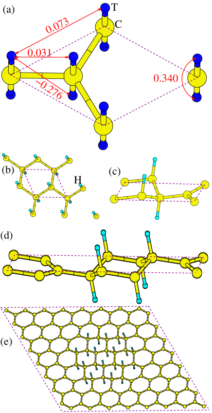
In the cluster expansion process, we consider the C2T4 alloy (see Fig. 1a) with the top sites T occupied by H atoms or vacancies. Our calculation shows that there are four important pair interactions as shown in Fig. 1a, and the three-body interactions are negligible. We can see that the interaction between two H atoms adsorbed on the same C atom is extremely repulsive (0.340 eV). This is understandable because the five-fold coordinated carbon is not stable. In contrast, we find that the interaction parameter between two H atoms adsorbed on different sides of the two adjacent C atoms is largely negative ( eV). The efficient strain relaxation and the absence of dangling bonds in this four-fold coordinated carbon configuration account for the stability. Using the cluster expansion Hamiltonian, we can easily obtain the energy of a given alloy configuration and thus the ground state structure of the partially hydrogenated graphene for a given supercell. It is clear that the number of H atoms (n[H]) should not exceed that of C atoms (n[C]) because otherwise some C atoms will bind with more than one H atoms. When n[H]/n[C] , the ground state structure is graphane (see Fig. 1b), as found by Elias et al.. [24] For n[H]/n[C] , the lowest energy structure among all possible configurations with no more than 4 carbon atoms per supercell is shown in Fig. 1c. The adsorbed H atoms adsorb on a 1D zigzag carbon chain such that each H atom has two neighbor H atoms adsorbed on the opposite side of neighboring C atoms. This is consistent with the fact that the hydrogenation of neighbor C atoms from opposite sides is energetically preferred. However, we find that the above structure is not the global ground state structure with n[H]/n[C] . For example, the lowest energy structure (Fig. 1d) among all possible configurations with no more than 8 carbon atoms per supercell has a lower energy by 44 meV/C than does the structure shown in Fig. 1c. This is so because the number of carbon-carbon - bonds is increased from 0.5/C (Fig. 1c ) to 0.625/C (Fig. 1d). It is expected that the global ground state of the partially hydrogenated graphene displays macroscopic phase separation between graphene and graphane regions. To confirm this point, we consider a large supercell () with 24 adsorbed H atoms. Using the Monte Carlo annealing technique, we find all the H atoms form a close packed cluster in the ground state configuration (Fig. 1e). This shows that, in the global ground state of a partially hydrogenated graphene, the phase separation into graphene and graphane parts would take place.
We also calculate the hopping barrier of an isolated H atom adsorbed on a carbon atom of graphene to the adjacent carbon atom using the nudged elastic band method.[25] The calculated barrier is eV, which is close to the value ( eV) in the case of the (8,0) CNT.[26] This suggests that isolated H atoms are relatively mobile, and thermal annealing would result in the formation of the macroscopic H cluster. Recently, Singh et al. [27] theoretically studied the electronic and magnetic properties of “nanoroads” of pristine graphene carved into the electrically insulating matrix of fully hydrogenated carbon sheet. However, our results suggest that it would be difficult to realize such patterned graphene nanoroads because of the tendency for phase separation into graphene and graphane parts.
Hydrogenation of 1D graphene nanoribbons
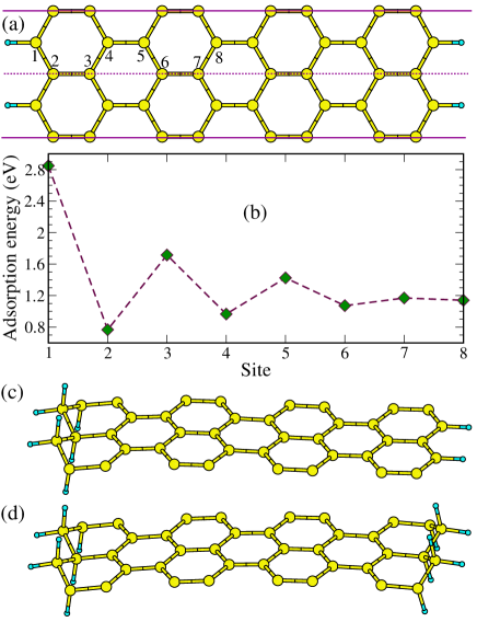
Now we turn to the study of hydrogenation of GNRs. There are two common types of GNRs. One kind of the GNRs, called zigzag GNR (ZGNR), has zigzag-shaped edges with the dangling bonds passivated by hydrogen atoms. Following conventional notation, we name the GNR shown in Fig. 2a as 8-ZGNR according to the number of zigzag chains along the ribbon. First, we consider the adsorption of a single H atom on 8-ZGNR using the supercell with two unit cells. The adoption of a larger cell leads to qualitatively similar results. To find the most stable configuration, we consider all nonequivalent possible adsorption sites indicated in Fig. 2a. We define the adsorption energy as:
| (1) |
where , , and are the total energies of an isolated H atom, the pristine GNR, and the GNR with an adsorbed H atom, respectively. Our calculated adsorption energies are shown in Fig. 2b. The positive adsorption energy is a consequence of the formation of CH bond. Remarkably, we find that the isolated H atom prefers to adsorb on the edge carbon atom (site 1) than other sites by at least 1.1 eV. This is because the number of carbon-carbon - bonds is the largest in this configuration, similar to the hydrogenated graphene case. Experimentally, it was found [28] that the atomic layer deposition of metal oxide on graphene grows actively on edges, indicating that the chemical reactivity at the edges of graphene is high,[29] which is consistent with our theoretical results. Interestingly, the dependence of the adsorption energy on the distance between the adsorbed site and the edge is not monotonous: It displays an odd-even oscillation with a smaller adsorption energy at even sites, and the adsorption energy of even (odd) sites increases (decreases) with the distance, and eventually the energy difference between even and odd sites adsorption becomes very small. The smallest adsorption energy at site 2 might be due to the presence of two rather unstable edge carbon atoms near site 2 that participate in the formation of only one bond.
A second H atom will adsorb on the opposite site of the carbon atom (site 2) adjacent to the edge carbon atom (site 1) to which the first H atom is bound, so as to saturate the broken bond. The adsorption energy of this configuration is 5.73 eV/(two H atoms), which is larger than the sum of the adsorption energies of a single H atom on site 1 and 2, indicating a cooperative adsorption behavior. This configuration is more stable than that with two H atoms adsorbed on two outermost edge carbon atoms, for which the adsorption energy (4.62 eV) is about twice the adsorption energy of a single H atom on an edge carbon atom. The third H atom is expected to adsorb on the edge carbon atom adjacent to the carbon atom to which the second H atom is bound. If the number of H atoms is equal to the total number of edge carbon atoms (on both edges), all the H atoms will adsorb on the outermost carbon atoms of one edge of the ZGNR, as shown in Fig. 2c, where the left edge is assumed without loss of generality. When the number of H atoms is twice the total number of edge carbon atoms, the excess H atoms will bind with the outermost carbon atoms of the right edge, resulting in a symmetric configuration (see Fig. 3d). The asymmetric configuration where all H atoms adsorb on the left side has a higher energy by 30 meV per edge carbon atom. Nevertheless, the asymmetric configuration has a similar electronic structure as the symmetric configuration except for a small asymmetric splitting in the band structure. Thus, our calculations suggest the following H adsorption scenario: The H atoms adsorb on the outermost zigzag bare carbon chain of one edge, and then on the outermost zigzag bare carbon chain of the other edge. The process of alternating hydrogenation continues until no more free H atom is available.
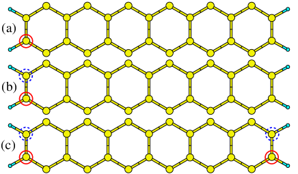
In the above discussion, we focused on the hydrogenation of ZGNRs. To be complete, we now investigate the hydrogenation of another kind of GNRs, namely, the armchair GNR (AGNR) with armchair-shaped edges. Similar to the case of ZGNRs, an isolated H atom also prefers to adsorb on the edge carbon atom (see Fig. S1 for the calculated adsorption energies), as shown in Fig. 3a for the case of 13-AGNR case. A second H atom will adsorb on the adjacent carbon atom of the edge CC dimer, as expected (Fig. 3b). It is found that four H atoms also adsorb symmetrically on the two edges of 13-AGNR (Fig. 3c). Therefore the H adsorption on AGNRs resembles that on ZGNRs except that the H atoms adsorb on AGNRs in a dimer-line-by-dimer-line manner.
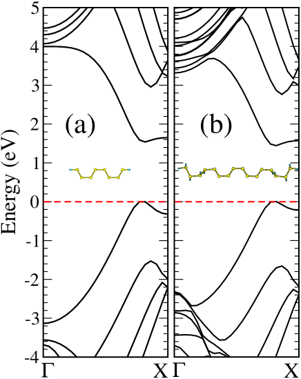
To understand the electronic and magnetic properties of partially hydrogenated GNRs, we compare partially hydrogenated 8-ZGNR with four bare zigzag carbon rows, hereafter referred to as 8-ZGNR-4, with 4-ZGNR without adsorbed H atoms as a representative example. In both cases, we find that the electronic ground state is the antiferromagnetic (AFM) state in which each of the two electronic edge states is ferromagnetically ordered but the two edge states are antiferromagnetically coupled to each other. For 8-ZGNR-4, the AFM state is meV/unit cell more stable than the ferromagnetic (FM) state, in which all spins are ferromagnetically aligned. A similar stability difference between the AFM and FM states is found for 4-ZGNR (i.e., meV/unit cell). Moreover, they almost have the same local magnetic moment ( ). Bacause the local density approximation is well known to seriously underestimate the band gap of semiconductors, we calculate the band structure of partially hydrogenated ZGNRs by employing the screened Heyd-Scuseria-Ernzerhof 06 (HSE06) hybrid functional, [30, 31, 32] which was shown to give a good band gap for many semiconductors including ZGNRs. [33] The HSE06 band structures calculated for 4-ZGNR and 8-ZGNR-4 in the AFM state are shown in Figs. 4a and b, respectively. In the energy region of the band gap, the band structure of 8-ZGNR-4 is similar to that of 4-ZGNR, and the band gap (1.44 eV) of 8-ZGNR-4 is close to that (1.53 eV) of 4-ZGNR. Therefore, the electronic and magnetic properties of partially hydrogenated wide GNRs are determined by those of its graphene part, i.e., the bare zigzag carbon rows. As already mentioned, semiconducting partially hydrogenated GNRs can be as transistors, and those with a small number of bare zigzag carbon rows might be used as a solar cell absorption materials: 8-ZGNR-4 (and N-ZGNR-4 with N) has a direct band gap that is close to the optimal value ( eV) [34] for the solar energy harvesting, and high carrier mobility.
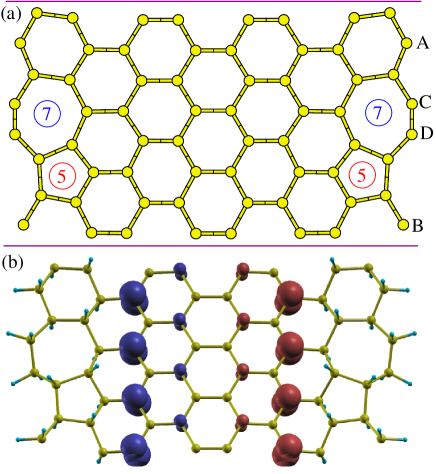
Experimentally, the edges of synthesized GNRs might be rough. It is interesting to see whether the resulting hydrogenated GNRs with rough edges have a similar electronic structure as do hydrogenated perfect GNRs. In order to address this issue, we study the hydrogenation of bare 8-ZGNR with Stone-Wales (SW) reconstructions at the edges (see Fig. 5a), which are typical defects for bare GNRs. [35] There are four edge carbon atoms per edge: two (C and D in Fig. 5a) of these belong to the 7-ring that form a triplet bond with each other, and the others (A and B in Fig. 5a) are isolated edge carbon atoms of the 6-ring. Due to the presence of dangling bonds at A and B sites, a single H atom will first bond to A or B site: The adsorption energy calculation shows that eV, eV, eV, and eV. Excess H atoms will adsorb gradually toward the inner part of GNRs. Shown in Fig. 5b is the partially hydrogenated 8-ZGNR containing SW defects with four zigzag bare carbon rows. For the two carbon atoms common to both 5-ring and 7-ring, two H atoms adsorb on them above the ribbon plane, as a result of the odd-membered ring. We find that this partially hydrogenated 8-ZGNR has a similar properties as 8-ZGNR-4; It is semiconducting with a similar band gap and the AFM state is more stable than the FM state by meV per ZGNR unit cell. The spin density plot of the AFM state (Fig. 5b) shows that the magnetic moments are also mainly due to the sp2 carbon atoms next to the sp3 carbon atoms. Therefore, partial hydrogenation can also convert a GNR with unsmooth edges into a GNR with perfect electronic and magnetic properties.
Concluding remarks
In summary, we performed a comprehensive first principles DFT study on the hydrogenation of graphene and GNRs. The hydrogen adsorption on graphene results in a complete phase separation between bare graphene and graphane. As for the hydrogen adsorption on GNRs, our study reveals the following rules: (i) Hydrogen atoms adsorb preferentially on the outermost edge carbon atoms. (ii) Hydrogen atoms lead to pairwise addition by adsorbing on adjacent carbon atoms in a one-up and one-down manner. (iii) The above adsorption process shifts from one edge to the other edge of a GNR, and this alternating hydrogenation process continues until there is no more free H atoms.
Our study suggests that the partial hydrogenation can make wide GNRs effectively “narrower” in their physical properties, because partially hydrogenated wide GNRs have electronic, optical, and magnetic properties similar to those of the narrow GNRs representing their graphene parts. Therefore, the experimental difficulty in synthesizing GNRs with narrow width and smooth edges could be bypassed through partial hydrogenation of wide GNRs. Partial hydrogenation might pave a way for the application of GNRs as transistors or novel carbon based solar cell absorption materials. In this study, we only consider the adsorption of H atoms. However, the concept should remain valid if other groups are used instead.
Acknowledgments
Work at NREL was supported by the U.S. Department of Energy, under Contract No. DE-AC36-08GO28308, and work at NCSU by the U. S. Department of Energy, under Grant DE-FG02-86ER45259.
Supporting Information Available:
The adsorption energies of one H atom on different carbon sites of 13-AGNR. This information is available free of charge via the Internet at http://pubs.acs.org/.
References
- [1] Castro Neto,A. H.; Guinea, F.; Peres, N. M. R.; Novoselov, K. S.; Geim, A. K. Rev. Mod. Phys. 2009, 81, 109.
- [2] Geim,A. K.; Novoselov, K. S. Nature Mater. 2007, 6, 183.
- [3] Son,Y.-W.; Cohen, M. L.; Louie, S. G. Nature (London) 2006, 444, 347.
- [4] Wakabayashi, K. Phys. Rev. B 2001, 64, 125428.
- [5] Barone, V.; Hod, O.; Scuseria, G. E. Nano Lett. 2006, 6, 2748.
- [6] Areshkin, D. A.; Gunlycke, D.; White, C. T. Nano Lett. 2007, 7, 204.
- [7] Kan,E. J.; Li, Z.; Yang, J.; Hou, J. G. J. Am. Chem. Soc. 2008, 130, 4224.
- [8] Yang, L.; Park, C. -H.; Son, Y. -W.; Cohen, M. L.; Louie, S. G. Phys. Rev. Lett. 2007, 99, 186801.
- [9] Li, X.; Wang, X.; Zhang, L.; Lee, S.; Dai, H. Science 2008, 319, 5867.
- [10] Wang,X. R.; Ouyang, Y. J.; Li, X. L.; Wang, H. L.; Guo, J.; Dai, H. J. Phys. Rev. Lett. 2008, 100, 206803.
- [11] Chen, Z.; Lin, Y.-M.; Rooks, M. J.; Avouris, P. Physica E 2007, 40, 228.
- [12] Han,M. Y.; Özyilmaz, B.; Zhang, Y.; Kim, P. Phys. Rev. Lett. 2007, 98, 206805.
- [13] Campos-Delgado, J. et al. Nano Lett. 2008, 8, 2773.
- [14] Jiao, L.; Zhang, L.; Wang, X.; Diankov, G.; Dai, H. Nature (London) 2009, 458, 877.
- [15] Kosynkin,Dmitry V.; Higginbotham, Amanda L.; Alexander Sinitskii,; Lomeda, Jay R.; Ayrat Dimiev,; Katherine Price, B.; Tour, James M. Nature (London) 2009, 458, 872.
- [16] Cano-Márquez, A. G. et al. Nano Lett. 2009, 9, 1527.
- [17] Sofo,Jorge O.; Chaudhari, Ajay S.; Barber, Greg D. Phys. Rev. B 2007, 75, 153401.
- [18] Boukhvalov,D. W.; Katsnelson, M. I.; Lichtenstein, A. I. Phys. Rev. B 2008, 77, 035427.
- [19] Lu, N.; Li, Z.; and Yang, J. arXiv:0904.4540.
- [20] Ferreira,L. G.; Su-Huai Wei,; Alex Zunger, Phys. Rev. B 1989, 40, 3197.
- [21] van de Walle,A.; Asta, M.; Ceder, G. CALPHAD Journal 2002, 26, 539. http://www.its.caltech.edu/~avdw/atat/.
- [22] (a) Blöchl,P. E. Phys. Rev. B 1994, 50, 17953; (b) Kresse,G.; Joubert, D. Phys. Rev. B 1999, 59, 1758.
- [23] Kresse, G.; Furthmüller, J. Comput. Mater. Sci. 1996, 6, 15; Phys. Rev. B 1996, 54, 11169.
- [24] Elias,D. C.; Nair, R. R.; Mohiuddin, T. M. G.; Morozov, S. V.; Blake, P.; Halsall, M. P.; Ferrari, A. C.; Boukhvalov, D. W.; Katsnelson, M. I.; Geim, A. K.; Novoselov, K. S. Science 2009, 323, 610.
- [25] Henkelman, G.; Uberuaga, B. P.; Jónsson, H. J. Chem. Phys. 2000, 113, 9901.
- [26] Zhang, Z.; Cho, K. Phys. Rev. B 2007, 75, 075420.
- [27] Singh,Abhishek K.; Yakobson, Boris I. Nano Lett. 2009, 9, 1540.
- [28] Wang, X.; Tabakman, Scott M.; Dai, H. J. Am. Chem. Soc. 2008, 130, 8152.
- [29] Wang, X.; Li, X.; Zhang, L.; Yoon, Y.; Weber, Peter K.; Wang, H.; Guo, J.; Dai, H. Science 2009, 324, 768.
- [30] Heyd,J.; Scuseria, G. E.; Ernzerhof, M. J. Chem. Phys. 2003, 118, 8207.
- [31] Krukau,A. V.; Vydrov, O. A.; Izmaylov, A. F.; Scuseria, G. E. J. Chem. Phys. 2006, 125, 224106.
- [32] Paier,J.; Marsman, M.; Hummer, K.; Kresse, G.; Gerber, I. C.; Ángyán, J. G. J. Chem. Phys. 2006, 124, 154709.
- [33] Hod, O.; Barone, V.; Scuseria, G. E. Phys. Rev. B 2008, 77, 035411.
- [34] Thompson, B. C., Fréchet, J. M. J. Angew. Chem., Int. Ed. 2008, 47, 58.
- [35] Huang, B.; Liu, M.; Su, N.; Wu, J.; Duan, W.; Gu, B.; Liu, F. Phys. Rev. Lett. 2009, 102, 166404.
![[Uncaptioned image]](/html/0905.1895/assets/x6.png)
TOC graphic