Generation of two-dimensional cluster states by using high-finesse bimodal cavities
Abstract
We propose two novel schemes to generate the two-dimensional and cluster states by using a chain of (two-level) Rydberg atoms in the framework of cavity QED. These schemes work in a completely deterministic way and are based on the resonant interaction of the atoms in a chain with a bimodal cavity that supports two independent modes of the photon field. We demonstrate that a cluster state can be generated efficiently with only a single bimodal cavity, while two such cavities are needed to produce a cluster state. It is shown, moreover, how these schemes can be extended towards the generation of two-dimensional cluster states.
pacs:
42.50.Pq, 42.50.Dv, 03.67.MnI Introduction
Entanglement is known today as a key feature and resource of quantum mechanics. It has been found important not only for studying the nonlocal and nonclassical behavior of quantum particles but also for a wide range of applications in quantum engineering and quantum information theory nc , such as super-dense coding bew , quantum cryptography eke , or the quantum search algorithm gro . Apart from the Bell states as prototypes of two-partite entangled states, various attempts have been made recently in order to produce and control entanglement also for more complex systems. Owing to the fragile nature of most of these states, however, the manipulation of larger quantum systems still remains a great challenge for experiment and only a few proof-of-principle implementations have been realized so far that generate entangled states with more than two parties in a well-controlled manner.
Recently, Briegel and Raussendorf BR1 have introduced a novel type of multi-partite entangled states. These (so-called) cluster states are known to exhibit a rather high persistency and robustness of their entanglement with regard to decoherence effects prl92a . Apart from the fundamental interest in these states pra71 and their use in quantum communication protocols pla364 , the cluster states also form the key ingredient for one-way quantum computations BR2 . In general, a cluster state can be constructed from an array of uncorrelated qubits by carrying out the following two steps: (i) the preparation of each qubit in the superposition , where and refer to the distinguishable basis states of some given two-level system, such as the spin projection of a spin-1/2 particle or the polarization of light, and (ii) the (subsequent) application of the controlled-z operation nc
| (1) |
between–some or all–pairs of neighboring qubits in order to entangle them with each other.
Since the original paper by Briegel and Raussendorf, the generation of cluster states has attracted much attention and has become a research topic by itself. Using a linear-optical set-up, for example, a proof-of-principle implementation of a four-qubit cluster state has first been reported by Walther and coworkers nat434 , and was utilized also by Tokunaga et al. tok08 in order to demonstrate basic operations for the one-way quantum computing. In the framework of cavity QED, in which neutral atoms are coupled to a high-finesse microwave or optical cavity, different schemes have been suggested during recent years to generate linear cluster states pra72 ; pra73 ; pra75 ; pra77a ; mps . In contrast to the linear cluster states, the two-dimensional cluster states would enable one to perform also multi-qubit gate operations (e.g. quantum gates that act on two or more qubits simultaneously) in one-way computations BR2 and, therefore, may result in a viable alternative to the conventional (circuit) computations in which sequences of unitary gates need to be carried out. Up to the present, nevertheless, only a minor progress has been achieved in Ref. oc281 with regard to schemes that generate two-dimensional cluster states within cavity QED. In this reference, the two-dimensional cluster state is obtained by combining two (or more) linear cluster states, which however, requires demanding experimental set-up and imposes certain restrictions on the geometry of the output cluster state.
In this paper, we suggest two practical schemes for the generation of two-dimensional and cluster states that are feasible for modern cavity QED experiments. These schemes work in a completely deterministic way and are based on the resonant interaction of a chain of Rydberg atoms with (high-finesse) bimodal cavities which, in contrast to a single-mode cavity, support two independent modes of the light field. While only one of these cavities is required for the generation of the cluster states, two (and more) cavities are needed to construct cluster states of larger size. Below, we describe the individual steps in the interaction of the Rydberg atoms with the cavity modes that are required to perform the suggested scheme. Here, we shall introduce also a graphical language in order to display all these steps in terms of quantum circuits and temporal sequences of the interactions that each of atoms undergoes. After all the atom-cavity interactions have been completed, the cluster state is encoded in the chain of atoms that has passed through one (in the first scheme for the cluster) or through two subsequent cavities (in the second scheme for the cluster). In addition, we also show how the suggested procedure can be extended to construct two-dimensional cluster states of arbitrary size, once a sufficiently large chain of atoms and an array of cavities are provided. We briefly discuss the implementation of one-way quantum computations within the given set-up in order to demonstrate that our approach is well suited for present-day experiments using bimodal microwave cavities. In addition, we briefly point to and discuss the main limitations that may arise experimentally in the generation of larger cluster states by using microwave cavities similar to those as utilized in the Laboratoire Kastler Brossel (ENS) in Paris.
The paper is organized as follows. In the next Section, we start with a brief reminder on the (resonant) interaction of one two-level Rydberg atom with a bimodal cavity. In Section II.A, we then recall the steps that are necessary in order to generate the linear cluster state, and which sets the stage also to discuss the generation of two-dimensional cluster states. In Section II.B, we present the scheme for the cluster state and, in Section II.C, for the state as well as for two-dimensional clusters of larger size. Finally, a summary and outlook are given in Section IV.
II Generation of cluster states by using bimodal cavities
The resonant atom-cavity interaction is perhaps the simplest regime that can be used to entangle the circular excited states of a Rydberg atom, in a well-controlled way, with the quantized field states of a cavity. For a sufficiently high quality (factor) of the cavity mirrors, this regime implies a strong atom-field coupling for which the dissipation of energy from the cavity becomes negligible during the interaction period. Indeed, a negligible dissipation is crucial for the engineering of multipartite entangled states between atomic qubits, if the cavity mediates this entanglement formation. Apart from the quality of the cavity, the correct matching of the atomic transition frequency to the resonant frequency of the cavity mode(s), the so-called detuning, is also important in order to realize a resonant interaction between the atom and the cavity.
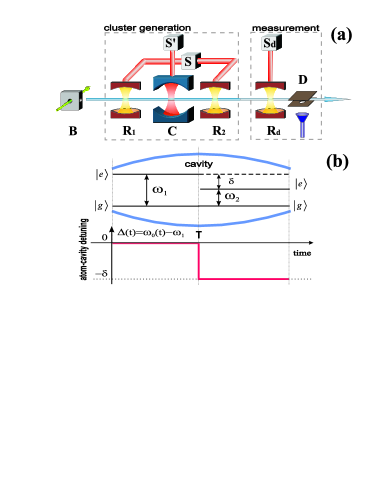
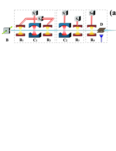
In the following, let us adopt here the language of the Haroche group haroche ; haroche1 for describing the cavity QED experiments and to specify the states of the atoms and the cavity. In the experiments of Haroche and coworkers, rubidium atoms are prepared to occupy one of the three Rydberg levels with principal quantum numbers 51, 50, or 49, and which are referred to as excited state , ground state , and auxiliary state , respectively. Owing to the particular design of the microwave cavity, however, only the states and can be involved in the atom-cavity interaction because only the transition frequency of an rubidium atom can be tuned to the frequency of the cavity mode(s). The classical microwave field from the sources , and [cf. Fig. 1(a)], in contrast, can be adapted to drive the or transitions and are utilized to generate or manipulate the superposition between these atomic states when the atom interacts with the microwave field.
The (time) evolution of an atom coupled to single-mode cavity is described by the Jaynes-Cummings Hamiltonian jc ()
| (2) |
where is the atomic transition frequency, the frequency of the cavity field, and the atom-field coupling frequency. In this Hamiltonian, moreover, and denote the annihilation and creation operators for a photon in the cavity, that act upon the Fock states , while and are the atomic spin lowering and raising operators that act upon the excitation states and , and which are the eigenstates of with eigenvalues and , respectively. Due to the Hamiltonian (2), the overall atom-field state evolves during the resonant interaction, e.g., for a zero detuning (), as
| (3a) | |||||
| (3b) | |||||
i.e. with a time evolution that is known also as Rabi rotation. In this (Rabi) picture, is the effective atom-cavity interaction time in the laboratory and is the corresponding angle of rotation. Note that neither the state nor appears in the time evolution (3) in line with our physical intuition that the photon energy is stored either by the atom or the cavity but should not occur twice in the system.
In contrast to a single-mode cavity, bimodal cavities support two non-degenerate modes of light with (usually) orthogonal polarization. Since the frequencies of these cavity modes are fixed by the design and geometry of the cavity mirrors, the atomic frequency need to be (de-)tuned in the course of the interaction such that the atom can interact resonantly with either the first or the second cavity mode. In the language of quantum information, the additional cavity mode gives rise to another photonic qubit that may interact independently with the atomic qubits, while they are passing through the cavity.
From the first experiments with bimodal cavities pra64 ; prl75 ; prl92 , their use has been found an important step towards the generation and control of entangled states. Indeed, a number of proposals pra68 ; jmo51 ; pra67 ; pra77 ; pla339 ; pra78 has been made in the literature in order to exploit further capabilities of bimodal cavities concerning, for example, the coherent manipulation of complex quantum states or for performing fundamental tests on quantum theory. Below, we shall denote the two cavity modes by and and assume that they are associated with the frequencies and , such that . For the cavity utilized in the experiments by Rauschenbeutel and coworkers pra64 , in particular, a frequency splitting of KHz was realized. Owing to this fixed splitting in the frequency of the field modes, we refer to the detuning of the atomic transition frequency with regard to the first cavity mode frequency: , briefly as the atom-cavity detuning.
An entanglement of a Rydberg atom with the photon field of the cavity is then achieved in a controlled way by tuning the transition frequency as function of time, so that it is in resonance with either one or the other cavity mode, while the atom passes through the cavity. For a sufficiently fast switch of the detuning , i.e. of the atomic frequency between the two modes of the cavity, a resonant interaction (regime) is realized with either mode for or with the mode for , cf. Figure 1(b), and where usually a step-wise change from the to the interaction is assumed. In the experiments by Haroche and coworkers, the detuning is changed by applying a well adjusted time-varying electric field across the gap between the cavity mirrors, so that the required (Stark) shift of the atomic transition frequency is obtained. Instead of the instantaneous (step-like) change of the atom-cavity detuning, however, only a–more or less–smooth switch can be realized for the detuning of the atomic frequency within the finite time of . In practice, such a finite switch is not completely negligible and may affect the evolution of the cavity states jpb . In the present work, however, we shall not consider the effects of this finite switching time but assume a step-wise change in the detuning as indicated in the lower part of Fig. 1(b).
Let us mention here, moreover, that the atom can interact resonantly at any given time only with one of the modes, while the second mode is then frozen out from the interaction because of the (large) splitting between the two cavity modes. Therefore, the overall time evolution of the atom-cavity state can be separated into two independent parts: the evolution that occurs due to the resonant interaction as displayed in Eq. (3), and the evolution due to
| (4a) | |||||
| (4b) | |||||
In the evolution above, the states and hereby refer to the Fock states of the cavity mode and the factor arises due to orthogonal polarization of the mode with respect to the mode .
With this short reminder on the Jaynes-Cummings Hamiltonian and the (atom-cavity) interactions in a bimodal cavity, we are now prepared to present all the steps that are necessary in order to generate one and two-dimensional cluster states for a chain of Rydberg atoms which crosses the cavity set-up.
II.1 Linear Cluster State
In this subsection, we first explain the generation of a linear cluster state for a chain of atoms, and for which only a single cavity mode is required. This scheme for the generation of linear states was first suggested by Schön and coworkers mps and will be adapted here for the cavity set-up as displayed in Fig. 1(a).
The linear cluster state is defined as BR1
| (5) |
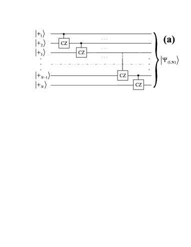
where acts on the -th qubit and . Alternatively one can define the linear cluster state also as a lattice of qubits, where the nodes refer to the qubits that are initialized (altogether) in the product state , and where the edges of the lattice refer to the two-qubit controlled-z gates (1) that are applied between neighboring nodes. According to this latter definition, Fig. 2(a) displays the successive interactions which are necessary to construct the linear cluster state for initially uncorrelated qubits. Instead of applying the controlled-z gate to each pair of neighboring qubits and , however, we can apply this two-qubit gate to the ancilla qubit and the ordinary qubit , and then swap the state of with the qubit as displayed in Fig. 2(b). Note that, in this circuit, we have inserted one additional swap gate between the ancilla and the first atom which has no effect on the output cluster state since the ancilla qubit is prepared initially also in the state .
Below we shall associate the ancilla qubit with the cavity mode and the ordinary qubits with the (two-level) Rydberg atoms. According to the second scheme from Fig. 2(b), this identification implies that the atoms pass sequentially through the cavity and that only one atom couples to the cavity at a time, which fits nicely to our cavity set-up displayed in Fig. 1(a). As seen from Fig. 2(b), moreover, only two types of unitary gates have to be performed between the cavity mode and the atoms that cross through the cavity, namely, (i) the swap gate followed by the controlled-z gate for atoms and (ii) the swap gate for the atom . Before the atom-cavity interaction starts, moreover, each atom must be prepared in the superposition . In the set-up above, this initial superposition is achieved by first exciting the atoms from the source into the state and then by applying the rotation
| (6) |
just before the atom enters the cavity. As explained below, the rotation (6) can be realized efficiently by means of the Ramsey zone .
The evolution of the atom-cavity state due to the resonant interaction of the atom with the cavity mode is given by Eqs. (3) which, for a Rabi rotation , is equivalent to the modified swap gate
| (7) |
expressed in the basis . In contrast to the conventional swap gate (which has no minus sign), we shall therefore refer to this two-qubit operation as m-swap gate below. Following the work by Schön and coworkers, we can express the m-swap gate (7) also in the form
| (8) |
where
| (9) |
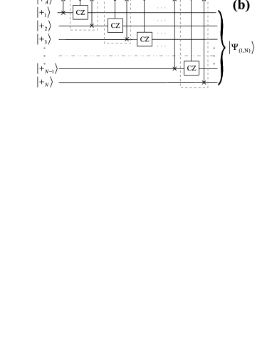
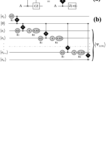
are the swap and controlled-z gates taken in the same basis as the matrix (7), and where denotes the standard rotation operator with regard to the (quantization) axis that acts upon the atomic state. Eq. (8) implies that the m-swap gate is equivalent (up to a constant phase) to the swap gate followed by the controlled-z gate together with a local rotation of the atomic state. In order to realize only the swap gate followed by the controlled-z gate as required by our scheme [see Fig. 2(b)], therefore, the m-swap gate (atom-cavity rotation) should be followed by the local rotation on the atom as depicted graphically in Fig. 3(a).
Up to this point, we just summarized a scheme that enables one to generate a linear cluster state by sending a chain of uncorrelated atoms through the cavity in such a way that only one atom couples to the cavity mode at a time. Specifically, we have shown that each atom is incorporated into the cluster state by performing the superposition (6) followed by a Rabi rotation of the atom-cavity system and finalized by a rotation of the atomic state. In order to fully adapt this scheme for our cavity set-up given in Fig. 1(a), it is necessary to express these atomic rotations in terms of those classical (field) pulses that can be generated by means of the microwave source . These pulses have to be applied when the atom passes through the Ramsey zones, either in front () and/or behind () of the cavity.
The interaction of a Rydberg atom with a (classical) microwave field gives rise to the unitary transformation of the atomic state haroche ; haroche1
| (10) |
expressed in the basis . In this rotation matrix, the angle is proportional to the duration of the microwave pulse, and an additional phase is accumulated whenever the microwave field frequency is slightly detuned from the atomic transition frequency. In the literature, such an interaction is often called a Ramsey pulse. Using the unitary matrix (10), it can be easily seen that one resonant Ramsey pulse gives rise to the rotation (6), and that the rotation around the axis
| (11) |
is obtained by applying two Ramsey pulses successively, where one is resonant and another one detuned by . In typical cavity QED experiments, a single Ramsey pulse takes about and thus implies that the atom is still inside of the Ramsey plates when the required rotation of the atomic state has been completed. Therefore, after a short time delay, it is possible to apply one additional (detuned) Ramsey pulse upon the same atom and within the same Ramsey zone. This enables one to realize the rotation (6) while the atom crosses the Ramsey zone in front of the cavity, and the rotation by the Ramsey zone just behind the cavity [see Fig. 1(a)].
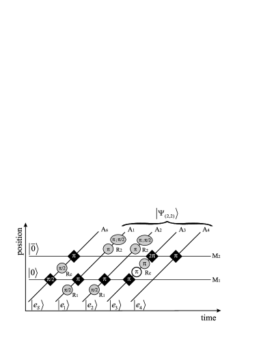
With this analysis, we now have all ingredients available to generate linear cluster states within our cavity set-up given in Fig. 1(a). The equivalent quantum circuit for this scheme is displayed in Fig. 3(b), in which the atom-cavity interactions are depicted by black diamonds (including the Rabi rotation angle), while the Ramsey pulses are shown as gray circles. For these Ramsey pulses, we also display the interaction time in units of rotation angle and the phase if it is non-zero. In addition, the letters or are utilized in order to denote the Ramsey zones in front or behind the cavity. Note that, in order to prepare the cavity mode in the state, we made use of an auxiliary atom that is initialized in the excited state and which crosses the cavity before the chain of atoms arrives. This auxiliary atom interacts for a Ramsey pulse with the microwave field and then for a Rabi pulse with the cavity. According to Eq. (6) and Eqs. (3), the initially empty cavity field is then set to the state, while the auxiliary atom is factorized out in its ground state. Let us also note that the last swap gate between the cavity and the -th atom is replaced by the m-swap gate (7), which simply maps the cavity state upon the atomic ground state and the cavity state upon the excited state . This replacement finally factorizes out the cavity state from the atomic cluster state.
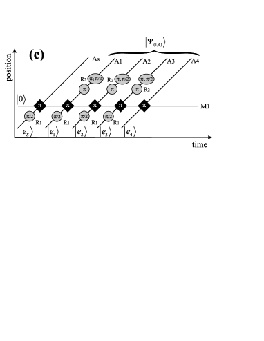
Fig. 3(c) shows the particular temporal sequence that can be applied for the generation of the four-qubit cluster state
for a chain of four atoms, where the notation has been used and the factorized state of the auxiliary atom and cavity mode is not displayed for brevity. This (temporal) sequence is just another way of presenting the set of Rabi and Ramsey pulses which was introduced originally by Haroche and coworkers in order to depict graphically the unitary evolution of the atom-field state in the framework of cavity QED. It is straightforward to check that one obtains (up to a constant phase) the state (II.1) if all the unitary transformations from this sequence are properly evaluated. It is also obvious that the state (II.1) is equivalent to the state (5) for by considering the assignments
| (15) |
In this subsection, we have shown that each atom from a chain of uncorrelated atoms is incorporated into the linear cluster state by performing a Rabi rotation and (if required) three Ramsey pulses: one applied before and two behind the cavity.
II.2 Cluster State
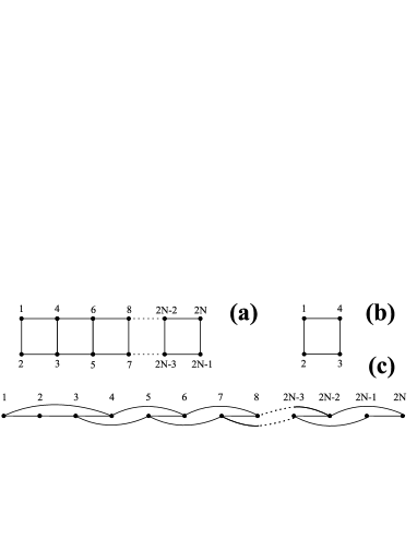
A linear cluster state alone is not sufficient for universal one-way quantum computations since its structure does not enable one to encode quantum gates that act upon several qubits. In this work, we therefore introduce a scheme that generates two-dimensional cluster states , i.e. states that form a two-dimensional lattice of qubits. In this lattice, the qubits are initialized in the state , and a controlled-z gate is applied for all edges that connect neighboring nodes, cf. Fig. 4(a). In fact, the concept of cluster states is neither restricted to a rectangular pattern of nodes not that only nearest neighbours could be connected with each other by a controlled-z operation. In the present work, however, we shall confine ourselves to two-dimensional clusters with rectangular geometry as displayed in Fig. 4(a).
The simplest example of such a two-dimensional cluster state is the (so-called) box state nat434
with . Note that this four-qubit cluster state could be obtained alternatively from the linear cluster state (II.1) by means of the transformations
| (17) |
and together with a change in the notation of the (atomic) qubits: and . These two transformations can be realized by applying the controlled-z gate that gives rise to the box configuration of Fig. 4(b) in which the first and the last qubits of the linear chain are now connected by an edge.
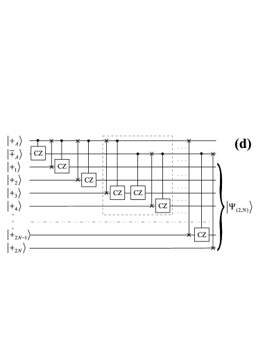
Following our set-up in Fig. 1(a), however, we made the (realistic) assumption from the very beginning that only a single chain of atoms is produced by the atomic source and sent into the cavity. For this reason, we need to consider a different procedure (if compared with the linear cluster states) for defining the edges between the nodes associated to a chain of atoms such that on the output, after all the atoms have crossed the cavity, an effective two-dimensional cluster state is generated. As mentioned above, bimodal cavities are designed in a way so they support two independent modes of the photon field. This makes it possible to implement schemes in which two (photonic) ancilla qubits are utilized due to the two cavity modes and . This enables us to generate the -partite entangled state displayed in Fig. 4(c) and that represents the two-dimensional cluster state upon the assignment of the atomic positions in a chain of atoms to the two-dimensional cluster state as shown in Fig. 4(a). The quantum circuit that accomplishes this task is displayed in Fig. 4(d), in which the gates that are placed inside of the dashed boxed area need to be repeated times. Apart from the unitary gate, which we introduced in the previous subsection, this circuit contains three additional gates. Two of them act upon the system: (i) the swap gate followed by the controlled-z gate, and (ii) a single controlled-z gate. The third gate is the controlled-z gate that acts upon the system. We shall discuss all of these operations now in turn.
Eqs. (4) display the evolution of the atom-cavity state for a resonant interaction of an atom with the cavity mode which, for a Rabi rotation , gives rise to the i-swap gate pra67a
| (18) |
expressed in the basis . Similar as in Eq. (8), we re-write this i-swap gate as
| (19) |
Therefore, the swap gate followed by the controlled-z gate is performed by applying the Rabi pulse followed by the local rotations of both, the atom and the cavity states, see also Fig. 5(a). A rotation of the atomic state can be easily implemented by utilizing two Ramsey pulses
| (20) |
separated from each other by a short time delay [cf. Eq. (11)]. Unfortunately, however, it is not easy to perform local operations on the cavity state. Therefore, we shall make use of the relation
| (21) |
which provides us with a hint, namely, we can replace the rotation of the cavity state during the step by the same rotation of the atomic state in the step . The diagram for this replacement is displayed in Fig. 5(b) and will be utilized in our further discussion.
Apart from the two basis states and of the atomic qubit, as applied in the atom-cavity interaction above, the Rydberg electron can populate also the auxiliary state below of the (ground) state . Therefore, we can utilize also the two states and in order to encode a qubit, which moreover, interacts with the cavity if there is one photon in the cavity mode. Following Eq. (4b), therefore, an atom prepared in a superposition of and is transformed due to
| (22a) | |||
| (22b) | |||
for the case of a full Rabi rotation of the atom-cavity state. Apparently, this transformation is the same as the controlled-z gate (9) if the states are taken as the basis. For this reason, we can use one full Rabi rotation to implement the single controlled-z gate by carrying out the following three steps: If the atom is initially prepared in a superposition of the and states, we expose it to the two resonant Ramsey pulses, with the first pulse being tuned to the transition frequency and the second pulse to . These two steps transfer coherently the state of the qubit
| (23) |
from the into the basis. After the transfer (23) has been made, a Rabi pulse is applied to the atom-cavity system that leads to the transformations (22), or equivalently, to a controlled-z gate between cavity mode and atomic qubit. Let us note here that the cavity by Haroche and coworkers has a small hole in the center of the upper cavity mirror which enables one to couple a microwave source to an atom that moves through the cavity [see Fig. 1(a)]. This microwave source, therefore, can be used to act successively on both, the and atomic transitions and implement the coherent transfer (23).
The last operation we should discuss here, is the controlled-z gate that acts upon the system and which is displayed in Fig. 4(d) in the terms of ancilla qubits. This gate acts on the cavity modes prepared in the state producing the entangled state
| (24) |
In fact, this state can be alternatively generated from the initially empty cavity by means of one auxiliary atom initialized in the excited state, which crosses the cavity before the main chain of atoms. This is achieved if the auxiliary atom first interacts for a Rabi pulse with the mode , then by a Ramsey pulse with the microwave source , and finally for a Rabi pulse with the mode . Using the Eqs. (6), (3) and (4), this sequence of pulses produces the state
| (25) |
while the auxiliary atom is factorized out in its ground state. In contrast to Eq. (24), in the Eq. (25) an extra factor occurs because of the orthogonal polarization of mode with respect to , which however, is compensated by the mapping operation ( Rabi pulse) as we shall see below.
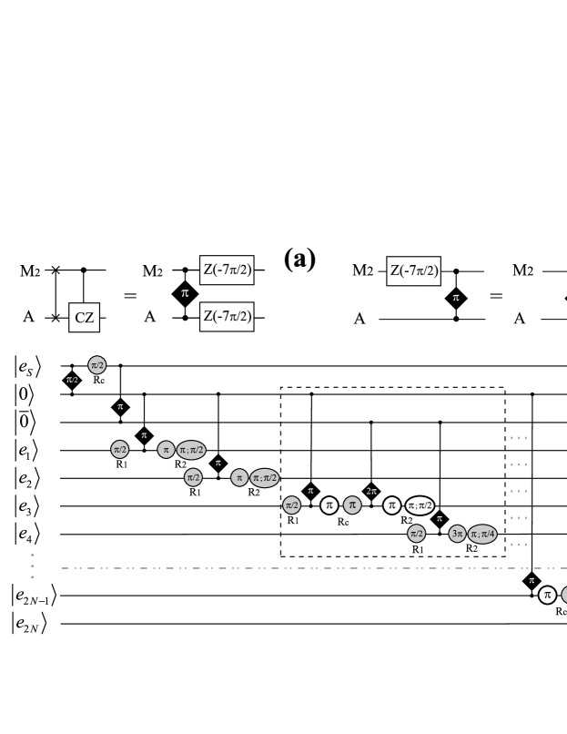
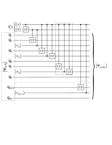
With this analysis of the individual (gate) operations, we have established all ingredients that are needed in order to generate the cluster state, and which are entirely adapted to our cavity set-up. The overall scheme is displayed in Fig. 5(c) in which the gates inside of the dashed box must be repeated times. In addition to the notation we have used before, the letter in this figure denotes the Ramsey zone inside of cavity and associated to the microwave source , while the white circle refers to a Ramsey pulse that is tuned to the atomic transition frequency. Note that the last gate ( Rabi pulse) maps the cavity states and upon the atomic and states together with factorization of the cavity mode in the state . According to the Eq. (4a), moreover, such a mapping implies one extra factor if the cavity mode was empty, which together with the factor from Eq. (25), gives rise to an irrelevant global phase.
To understand better the scheme for the generation of cluster state, Fig. 6 displays (the temporal sequence of) all steps that are needed to generate the box state
from Fig. 4(b). For the sake of brevity, neither the state of the auxiliary atoms and the cavity is shown in this expression since they are both factorized out after the sequence of steps has been completed. Obviously, the state (II.2) is equivalent to the state (II.2) by making the assignments
| (29) |
In this subsection, we have shown that each atom from a chain of uncorrelated atoms is incorporated into the cluster state by performing a Rabi (or followed by ) rotation and (if required) Ramsey pulses applied before, inside, and/or behind the cavity.
II.3 Cluster State
In the last two subsections, we have seen how to generate the cluster state by means of a single-mode cavity and how to get a cluster state by using a bimodal cavity. Since light has only two different polarization states, obviously, one cannot use one similar technique to generate the cluster state by just utilizing a single cavity device.
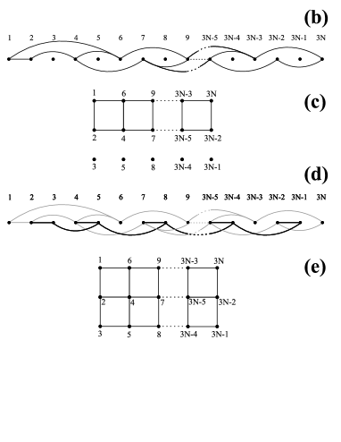
In this subsection, instead, we shall present and explain a scheme that enables one to generate a cluster state by using an array of two bimodal cavities, i.e. simply by placing one additional cavity and one Ramsey zone behind the zone , and before the detection area (at the Ramsey zone ) as shown in Fig. 7(a). This scheme can be divided into the following two steps: (i) implementation of the controlled-z gates (edges) within a chain of atoms according to Fig. 7(b), which lead to the generation of a cluster state, such that the third row of atoms remains disconnected from all other atoms as displayed in Fig. 7(c). Only the cavity and microwave sources and are utilized in this step, and the circuit that generates these edges is the same as shown in Fig. 5(c) up to a re-assignment of the atomic labels. All the atoms that remain disconnected during this step simply pass through the first cavity being detuned from the resonance () with both cavity modes, and therefore, without interacting with the cavity modes. (ii) The second cavity and microwave sources and are then utilized in order to create the additional (black) edges according to Fig. 7(d). This step completes the generation of the cluster state in which all neighbors are connected to each other as displayed in Fig. 7(e).
Neither of these two steps do require any additional atom-cavity gates that has not been described and discussed in the previous subsections. Therefore, this procedure enables us to construct the cluster states in a way which is well adapted to our set-up with two bimodal cavities. Because the first step can be realized by applying the circuit from Fig. 4(d), we need to display and discuss here only the circuit for the second step. This is shown in Fig. 8, where the gates inside of the dashed box must be repeated times. Similar as above, this circuit can be translated in a straightforward way into a temporal sequence of the atom-cavity interactions and single atomic gates.
By having understood the construction of the cluster states, we can use the recipe from Fig. 7 to generate the two-dimensional regular cluster states of arbitrary size. Similarly as the cluster state is obtained from the cluster and disconnected qubits, one can insert more cavities into the experimental set-up in order to generate cluster state (by means of cavities in total), and with a proper assignment of the atomic labels to the nodes of the cluster state.
Of course, there may arise the question of how many atoms from one atomic chain can be incorporated in a cluster state, in line with the recent developments in cavity QED? To obtain some rough estimate, let us consider a scenario in which each atomic qubit can be built into the cluster state for the price of a Rabi rotation. If we assume that the (minimum) distance between any two subsequent atoms in the chain is equal to the double waist length of the cavity mode, then, the number of atoms is approximately related to the lifetime of the atom-cavity system via relation
| (30) |
where denotes the required time for a single Rabi rotation and is a factor which accounts for all corrections to our idealized scheme. Such corrections may concern the imperfect realization of the Rabi and Ramsey pulses, the overlapping interaction of two atoms from the chain with the same cavity mode, the effects of noisy channels and stray fields, and others. In practise, such additional disturbances may lead to a much smaller number of atoms that can be treated coherently. For the atomic velocity , that was utilized in the microwave cavity experiments by Haroche and coworkers, a single Rabi rotation takes about . Moreover, the lifetime of the atom-cavity system is limited mainly by the radiative lifetime of the atoms (while the cavity coherence time is much longer). Therefore, by making a conservative estimate for the correction factor in Eq. (30), say , we still obtain atoms which may pass the cavity within the given lifetime.
II.4 Remarks on the Realization of Proposed Schemes
Obviously, the realization of large (entangled) cluster states with a trustworthy fidelity is an experimental challenge by itself. In the earlier cavity-QED experiments by Rauschenbeutel and coworkers sc288 , the generation of a three-partite Greenberger-Horne-Zeilinger state (that is equivalent to the linear cluster state) was reported with a fidelity of %, that is just above the threshold which is necessary to prove the generation of this state. In this subsection, we shall therefore discuss the main limitations that may arise experimentally in the generation of larger cluster states by using microwave cavities similar to those as applied in the Laboratoire Kastler Brossel (ENS) in Paris.
One of the main bottleneck in cavity-QED experiments is the low surface quality of the cavity mirrors, i.e. the local roughness and the deviations from the spherical geometry. These defects cause the scattering of photons outside the cavity mode and thus reduce the coherent storage time of photons within the cavity. The storage time of photons, in turn, limits the number of quantum operations (gates) that can be performed successively before the atom-cavity state becomes destroyed. This rapid loss of coherence during the evolution of the atom-cavity state has stimulated Haroche and coworkers to develop a new ultrahigh-finesse cavity devices apl90 for which the quality factor was increased by about two orders of magnitude. Such a high quality factor enables to perform more than hundred quantum logical operations within the lifetime of a photon inside the cavity (see estimations in the previous subsection). Moreover, in order to minimize the contribution of thermal photons that occur in microwave cavities due to thermal fields, the cavity was cooled down to K which yields an average number of thermal photons. This ensures that the contributions of thermal photons can be neglected for the evolution of the cavity states.
In practice, the atoms that are emitted from the atomic source have a spread in their velocities. For a given chain of atoms, such a spread will lead to small deviations in the time intervals of the atom-cavity interactions and will introduce uncertainties in the duration of Rabi and Ramsey pulses. In order to minimize this velocity spread, a velocity selector has been placed right after the atomic source in experiments by Haroche and co-workers. This selector reduces the velocity spread to m/s haroche1 which being compared to the typical velocity of m/s of the atoms, implies that the error due to the velocity spread is less than one percent and negligible for most purposes. The small spread in the velocities gives rise also to a small spatial dispersion ( mm) of the atomic positions while they pass through the cavity. This spatial dispersion compared to the resonant cavity wavelength ( mm) implies that only a small deflection from the cavity antinode may occur and may yield a similar small deviation of the atom-cavity coupling from its nominal value.
Indeed, the control and manipulation of the resonant cavity frequency is essential in order to achieve a resonant atom-cavity interaction regime. Any deviation from this resonant regime would lead to spurious matrix elements in the atom-cavity gates (7) and (18). In the experiments by Haroche and co-workers, the cavity frequency is manipulated by slightly changing the distance between the cavity mirrors. By making use of a piezoelectric stack placed under the lower cavity mirror, a fine tuning of the cavity length was achieved with MHz range, which has to be compared to the atomic transition frequency GHz. Again, such small deviations in the length seems to be negligible. In the present work, however, we consider a bimodal cavity scenario in which the atomic transition frequency is tuned to the first or second cavity mode by applying a time-varying electric field across the cavity gap, such that the required (Stark) shift of the atomic transition frequency is obtained. As explained in the beginning of this section, a rather smooth switch of the atom-cavity detuning is produced within the finite time of that could affect the evolution of the cavity states jpb whenever the switching pulse is comparable to the Rabi pulse.
Finally, in order to describe the real evolution of the atom-cavity system, one would have to include also the interaction with the environment that has been omitted from the present considerations. As pointed out in the beginning of this section, the resonant atom-cavity interaction regime implies a negligible dissipation of the cavity field during all the atom-cavity interaction time periods. By setting sufficient distance between the atoms in a chain, events with several atoms in the same cavity mode are avoided. However, such a distance may yield the cavity to be empty and thus field dissipation would have to be taken into account. A detailed investigation of the evolution of bimodal cavity states with dissipation has been performed by Magalhaes and Nemes pra70 and the dynamics of the cavity-field relaxation has been understood. On the other hand, a quantum simulator has been developed in our group cpc175 which could be utilized in future studies to investigate the role of decoherence on the evolution of cluster states. Overall, we conclude that further improvement of the cavity mirrors quality factor and the time-varying electric field characteristics are needed in order to produce large cluster states by the suggested schemes with a good fidelity.
III Summary and Outlook
In this work, two novel schemes are presented to generate the two-dimensional and cluster states within the framework of cavity QED. These schemes are based on the resonant interaction of a chain of Rydberg atoms with one or two bimodal cavities, i.e. cavities that support two independent modes (with orthogonal polarization) of the photon field. In addition, we have shown and discussed how the scheme for the cluster state can be extended also for the construction of two-dimensional cluster states of arbitrary size. This is achieved by using bimodal cavities in a row. Using the graphical language of temporal sequences and quantum circuits, a comprehensive description of all necessary gates and manipulations is provided. We stress that the given scheme(s) can easily be adapted to the present-day microwave cavity QED experiments although their realization is still a challenge, especially if one is interested in cluster states with .
The results of this paper also suggest that cavity QED provides a suitable framework not only for the generation of cluster states but also for one-way quantum computations which are performed by a sequence of single-qubit projective measurements (with possible feedforwarding). For these computations, a cluster state of appropriate size is needed together with two types of measurements BR2 : (i) measurement in the basis and (ii) measurement in the basis
| (31) |
where denotes a real number. Those qubits which are not projected (measured) finally, encode the output quantum state.
To see how the one-way quantum computations fit into the framework of cavity QED, we can reconsider the set-up displayed in Fig. 1(a). In this figure, a particular cluster state is generated within a chain of atoms emitted by the atomic source after it crosses the cavity and microwave sources. This cluster state, being encoded in the atomic chain, then enters into the detection region, where each (Rydberg) atom is projected upon one of its levels , , or and by which, therefore, the measurement in the basis (i) is performed. In order to perform also the measurement in the basis (ii), a Ramsey zone is installed and applied before the detector. It can be shown prl79 ; sc288 that a Ramsey pulse detuned by the value of from atomic resonance followed by a detection of the atom in the basis (i), is equivalent to a projective measurement in the basis (31). The last (unmeasured) atoms inside the atomic chain, encode the final output quantum state. We may conclude, therefore, that all necessary ingredients are available in order to perform one-way quantum computations in the framework of cavity QED, including also the preparation of the cluster state in the same set-up.
Acknowledgements.
This work was supported by the DFG under the project No. FR 1251/13.References
- (1) M. A. Nielsen, I. L. Chuang, Quantum Computation and quantum Information, (Cambridge University Press, Cambridge, 2000).
- (2) C. H. Bennett and S. J. Wiesner, Phys. Rev. Lett. 69, 2881 (1992).
- (3) A. K. Ekert, Phys. Rev. Lett. 67, 661 (1991).
- (4) L. K. Grover, Phys. Rev. Lett. 79, 325 (1997).
- (5) H. J. Briegel and R. Raussendorf, Phys. Rev. Lett. 86, 910 (2001).
- (6) W. Dür and H.-J. Briegel, Phys. Rev. Lett. 92, 180403 (2004).
- (7) V. Scarani, A. Acín, E. Schenck, and M. Aspelmeyer, Phys. Rev. A 71, 042325 (2005).
- (8) X.-W. Wang, Y.-G. Shan, L.-X. Xia, and M.-W. Lu, Phys. Lett. A 364, 7 (2007).
- (9) R. Raussendorf, D. E. Browne, and H. J. Briegel, Phys. Rev. A 68, 022312 (2003).
- (10) P. Walther et al., Nature 434, 169 (2005).
- (11) Y. Tokunaga, S. Kuwashiro, T. Yamamoto, M. Koashi and N. Imoto, Phys. Rev. Lett. 100, 210501 (2008).
- (12) X. B. Zou and W. Mathis, Phys. Rev. A 72, 013809 (2005).
- (13) P. Dong, Z.-Y. Xue, M. Yang, and Z.-L. Cao, Phys. Rev. A 73, 033818 (2006).
- (14) X. L. Zhang, K. L. Gao, and M. Feng, Phys. Rev. A 75, 034308 (2007).
- (15) J.-Q. Li, G. Chen, and J.-Q. Liang, Phys. Rev. A 77, 014304 (2008).
- (16) X.-W. Wang and G.-J. Yang, Opt. Commun. 281, 5282 (2008).
- (17) J. M. Raimond, M. Brune, and S. Haroche Rev. Mod. Phys. 73, 565 (2001).
- (18) S. Haroche, J. M. Raimond, Exploring the Quantum: Atoms, Cavities, and Photons (Oxford Univeristy Press, 2006)
- (19) E. T. Jaynes and F. W. Cummings, Proc. IEEE 51, 89 (1963).
- (20) A. Rauschenbeutel et al., Phys. Rev. A 64, 050301(R) (2001).
- (21) Q. A. Turchette, C. J. Hood, W. Lange, H. Mabuchi, H. J. Kimble, Phys. Rev. Lett. 75, 4710 (1995).
- (22) L. M. Duan and H. J. Kimble, Phys. Rev. Lett. 92, 127902 (2004).
- (23) M. S. Zubairy, M. Kim, and M. .O. Scully, Phys. Rev. A 68, 033820 (2003).
- (24) A. Biswas, G. S. Agarwal, J. of Modern Optics 51, 1627 (2004).
- (25) C. Wildfeuer and D. H. Schiller, Phys. Rev. A 67, 053801 (2003).
- (26) D. Gonta, S. Fritzsche, and T. Radtke, Phys. Rev. A 77, 062312 (2008).
- (27) A. R. Bosco de Magalhaes and M. C. Nemes Phys. Lett. A 339, 294 (2005).
- (28) J. Larson, Phys. Rev. A 78, 033833 (2008).
- (29) D. Gonta and S. Fritzsche, J. of Phys. B 41, 090101 (2008).
- (30) C. Schön, E. Solano, F. Verstraete, J. I. Cirac, and M. M. Wolf, Phys. Rev. Lett. 95, 110503 (2005); C. Schön, K. Hammerer, M. M. Wolf, J. I. Cirac, and E. Solano, Phys. Rev. A 75, 032311 (2007).
- (31) N. Schuch and J. Siewert, Phys. Rev. A 67, 032301 (2003).
- (32) A. Rauschenbeutel et al., Science 288, 2024 (2000).
- (33) S. Kuhr et al., Appl. Phys. Lett. 90, 164101 (2007).
- (34) A. R. Bosco de Magalhaes and M. C. Nemes, Phys. Rev. A 70, 053825 (2004).
- (35) T. Radtke and S. Fritzsche, Comput. Phys. Commun. 175, 145 (2006).
- (36) E. Hagley, et al., Phys. Rev. Lett. 79, 1 (1997).