The High-Acceptance Dielectron Spectrometer HADES
Abstract
HADES is a versatile magnetic spectrometer aimed at studying dielectron production in pion, proton and heavy-ion induced collisions. Its main features include a ring imaging gas Cherenkov detector for electron-hadron discrimination, a tracking system consisting of a set of 6 superconducting coils producing a toroidal field and drift chambers and a multiplicity and electron trigger array for additional electron-hadron discrimination and event characterization. A two-stage trigger system enhances events containing electrons. The physics program is focused on the investigation of hadron properties in nuclei and in the hot and dense hadronic matter. The detector system is characterized by an 85 % azimuthal coverage over a polar angle interval from to , a single electron efficiency of 50 % and a vector meson mass resolution of 2.5 %. Identification of pions, kaons and protons is achieved combining time-of-flight and energy loss measurements over a large momentum range. This paper describes the main features and the performance of the detector system.
keywords:
Spectrometer , Electron-positron pairs , Relativistic heavy-ion collisions , Hadron propertiesPACS:
21.65 , 24.85 , 25.75 , 29.30 , 29.401 Introduction
1.1 Physics motivation
A central topic of contemporary hadron physics is the investigation of hadronic matter. Theoretical models based on non-perturbative Quantum Chromo-Dynamics indicate that the properties of hadrons are modified, if the particles are embedded in a strongly interacting medium (for a theory overview see [rapp_wambach]).
The High-Acceptance DiElectron Spectrometer (HADES) in operation at the GSI Helmholtzzentrum für Schwerionenforschung has been specifically designed to study medium modifications of the light vector mesons [schicker_nim]. Experimentally, these probes are well suited for two reasons. The vector mesons are short-lived with lifetimes comparable to the duration of the compression phase of relativistic heavy-ion reactions in the 1 to 2 AGeV regime of the heavy-ion synchrotron SIS18. Equally important is their electromagnetic decay branch into ee pairs. This channel is not subject to strong final state interaction and thus provides an undistorted signal of the matter phase. The goal of the HADES experiments is to measure the spectral properties of the vector mesons such as their in-medium masses and widths.
The HADES heavy-ion program is focused on incident kinetic energies from 1 to 2 AGeV. Above about 0.7 AGeV these nucleus-nucleus reactions become increasingly complex as new particles - predominantly mesons - are produced which induce secondary reactions [metag]. Some of these elementary reactions are not well known and need to be explored as well. While relativistic heavy-ion collisions produce hadronic matter at a few times normal nuclear matter density and elevated temperature, pion or proton induced reactions embed vector mesons into normal nuclear matter. A dedicated physics program including heavy ions, deuteron, proton and pion beams has been proposed for the HADES detector [piotr_erice, juergen].
Dilepton decays of vector mesons at SIS energies are rare events and their observation presents a challenge for the detector design. Thus, HADES has been equipped with a hadron-blind ring imaging Cherenkov counter, a tracking system and a multiplicity and electron trigger array. A two-stage trigger system selects events containing electron candidates in real time. With its much larger solid angle and improved resolution, HADES continues and has the capability to complete the physics program which was pioneered by the DLS spectrometer at the BEVALAC [dls].
1.2 Detector overview
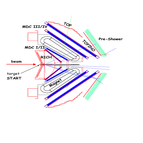
HADES features six identical sectors defined by the superconducting coils producing the toroidal geometry magnetic field. The spectrometer has 85 % azimuthal acceptance and covers polar angles between and . The angular and momentum acceptance has been optimized for the detection of dielectron decays of hadrons produced in the SIS energy regime. A section of the detector in the vertical plane containing the beam axis is shown in fig. 1.
Momentum reconstruction is carried out by measuring the deflection angle of the particle trajectories derived from the 4 hit positions in the planes of the Mini-Drift Chambers (MDC) located before and after the magnetic field region. Electron identification is performed with the hadron-blind gas Ring Imaging Cherenkov detector (RICH) together with the Multiplicity and Electron Trigger Array (META) consisting of time-of-flight scintillator walls (TOF/TOFINO) and electromagnetic shower detectors (Pre-Shower). A powerful two-stage trigger system is employed to select events within a predefined charged particle multiplicity interval (first-level trigger LVL1), as well as electron candidates (second-level trigger LVL2).
In the following, a detailed description of the main spectrometer components is given: magnet (sect. 2.1), RICH (sect. 2.2), tracking system (sect. LABEL:Chapter_MDC), META (sects. LABEL:Chapter_tof and LABEL:Chapter_shower) and beam detectors (sect. LABEL:Chapter_start). The detector description is followed by a discussion of the data acquisition and trigger system (sect. LABEL:Chapter_daq). The data analysis framework and the detector performance are discussed in sect. LABEL:Chapter_simana.
2 Major spectrometer components
2.1 Magnet
2.1.1 Basic design considerations
The purpose of the magnet is to provide a transverse kick to charged particles in order to obtain their momenta with sufficient resolution being of the order of = 1.5 - 2 % for electrons. On the other hand, electron identification with the RICH detector requires a nearly field free region around the target. Furthermore, a large momentum range of = 0.1 - 2 GeV/c should be accepted simultaneously within a large solid angle (, as close as possible to full azimuthal coverage). Simulations of reactions in the SIS18 energy regime have shown that these requirements call for a non-focusing spectrometer with a transverse momentum kick of about 0.05 to 0.1 GeV/c, where is the momentum difference between the incoming and outgoing momentum vectors in the plane perpendicular to the field. The is proportional to the product of magnetic field strength and path length . Assuming a magnetic field path length of m, in order to keep the spectrometer compact, the respective magnetic field strength stays below = 0.9 T.
For such a design, the required momentum resolution can be obtained only by keeping multiple scattering in the region of large magnetic field as small as possible (i.e. allowing no detector material in this region). For high momentum electrons ( 1 GeV/c), = 0.1 GeV/c also puts constraints on the position resolution of the particle detectors (MDCs) in front and behind the field region. For example, at = 1 GeV/c and = , the deflection angle amounts to for GeV/c. A simple model calculation assuming two sets of two detectors each spaced by m shows that for this case a position resolution of better than 150 m is required to keep the corresponding contribution to the momentum resolution below 1 %.
2.1.2 Field geometry
The toroidal field geometry provides a field free region around the target and inside the active volume of the RICH. Since the shadow of the coils can be aligned with the detector frames, no additional loss of solid angle is caused by the coils. Although the field strength is rather low, superconducting coils are necessary in order to obtain a compact coil construction. An additional advantage is the low operating cost.
2.1.3 Superconducting coils
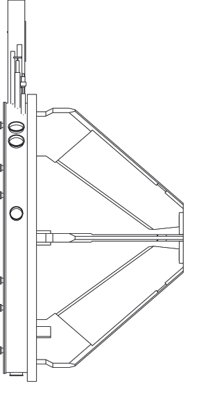
The system consists of 6 coils surrounding the beam axis. Each coil is separately contained in its individual vacuum chamber. The latter ones are connected to a support ring located upstream of the target. Figure 2 shows a side and a back view of the magnet including the support structure of the coil cases. A hexagonal plate, with a hole for the beam pipe, connects the back end of the six coil cases. Through this plate and the support ring, the magnetic forces acting on the coil cases of about N per coil are compensated. The ring upstream of the target supports the electrical connections between the coils as well as the Helium and Nitrogen cooling lines. No support structure is needed in the region where the drift chambers are located. Furthermore, no material is placed in a (starting from the target) cone around the beam axis.

Each coil consists of 2 non-parallel long straight sections connected by two arcs. The magnetomotive force of a coil amounts to 485000 Ampere-turns. Each coil has 140 turns, thus 3464 A have to be fed through the current leads. The angles of the entrance and exit sections of and were chosen to minimize the azimuthal deflection of particles over the whole range of polar angles. Due to the V-shape of the coil a small net focusing - or defocusing, depending on the particle charge - with respect to the azimuthal angles is obtained. The shape and orientation of the coil result in a stronger at small polar angles (see table 1). For beam energies of 1 - 2 AGeV, the transverse momentum kick provided by the field follows roughly the kinematical variation of the particle momenta with polar angle.
As explained in sect. LABEL:Chapter_kickplane below, the particle momentum can be calculated from the relation
| (1) |
where represents the leading term (see table 1). The coefficients and are correction terms accounting for the variation of the track length through the field and depend on the sign of the charge. All coefficients depend strongly on and .
| [MeV/c] at | 109 | 89 | 73 | 55 | 41 |
| [MeV/c] at | 123 | 94 | 76 | 61 | 53 |
| [MeV/c] at | – | 99 | 82 | 73 | 85 |
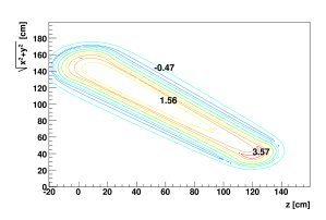
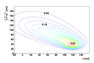
The field maps exhibited in fig. 3 show the strong inhomogeneity of the field as a function of both polar and azimuthal angles. The maximum field is obtained at the forward arc of the coil and amounts to 3.6 T at the sector edge (). The field of each sector was mapped using Hall probes and a dedicated optical positioning system. After correcting for the earth magnetic field, the measured field values agree with the ones calculated by TOSCA [Tosca] within better than 1 %. This shows that we have a full control of the coil geometry. The agreement with the integrated field (straight line through the field region) is better than 0.2 %.
2.1.4 Cryo plant
The coils are surrounded by a liquid Nitrogen cooled shield at 85 K. The flow through this shield amounts to 2 g/s including all shielding components. The remaining heat load of each coil amounts to 2 W. Together with the heat load on all other components, the total load amounts to 20 W excluding the current leads. The current leads are cooled with He gas, starting at 4.7 K and warming up to about 270 K. The heat load depends nearly quadratically on the current with a maximum load of 80 W (corresponding to 0.7 g/s) at full field. Thus, at full field, the cryo plant (TCF20, [Lindekryo]) has to provide a cooling power of 100 W, quite close to its 110 W limit. All heat loads refer to an equivalent cooling power at 4.7 K. In order to avoid gas bubbles inside the thin He pipes cooling the coils, single phase He at 4.7 K and 0.29 MPa is used. Above 0.23 MPa (critical point), Helium remains in the gas phase even at low temperatures, with density above the liquid phase at pressures below 0.23 MPa. It is afterwards liquefied by expanding to 0.13 MPa, providing thermal stability via heat exchangers, connecting thermally the cooling pipes with the liquid reservoir.
2.2 The RICH
2.2.1 Overview
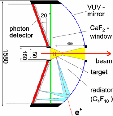
The Ring Imaging Cherenkov (RICH) detector constitutes the innermost part of the spectrometer and is designed to identify relativistic e with momenta 0.1 GeV/c 1.5 GeV/c. The layout, shown in fig. 4, is governed by the limited space between target and tracking detectors and by the need for a low material budget along the particle trajectories to minimize external pair conversion and multiple scattering. The photon detector is placed upstream of the target to spatially decouple the registration of the Cherenkov light from charged particle tracks emitted from the target. The choice of a gaseous photon detector with a photosensitive CSI cathode restricts the sensitivity to the far vacuum ultra violet (VUV) wavelength region.
The radiator gas perfluorobutan (CF) offers high transmission down to = 145 nm and a suitable Cherenkov threshold (Lorentz factor = 18) to suppress radiation from muons and hadrons in the given momentum regime. It surrounds the target station in an essentially field free region and is confined by a thin Carbon fiber shell at forward angles (thickness = 0.4 mm), by the photon detector CaF entrance window and by thin Mylar foils on the beam path. The Cherenkov light is radiated from straight particle trajectories with effective path lengths varying from 36 cm at to 65 cm at .