Drop impact upon micro- and nanostructured superhydrophobic surfaces
Abstract
We experimentally investigate drop impact dynamics onto different superhydrophobic surfaces, consisting of regular polymeric micropatterns and rough carbon nanofibers, with similar static contact angles. The main control parameters are the Weber number and the roughness of the surface. At small , i.e. small impact velocity, the impact evolutions are similar for both types of substrates, exhibiting Fakir state, complete bouncing, partial rebouncing, trapping of an air bubble, jetting, and sticky vibrating water balls. At large , splashing impacts emerge forming several satellite droplets, which are more pronounced for the multiscale rough carbon nanofiber jungles. The results imply that the multiscale surface roughness at nanoscale plays a minor role in the impact events for small but an important one for large . Finally, we find the effect of ambient air pressure to be negligible in the explored parameter regime .
I Introduction
Drop impact on a solid surface is ubiquitous and crucial in a variety of industrial processes. The interplay of several experimental conditions often makes the impact dynamics surprising and too complex to elucidate Yarin (2006). The control parameters include the impact velocity, liquid density, viscosity, surface tension, and the wettability and roughness of the substrates. In the past decade, the investigations have actively focused on the impacts upon superhydrophobic substrates Quéré (2008); Richard and Quéré (2000); Richard et al. (2002); Biance et al. (2004); Bartolo et al. (2006); Reyssat et al. (2006); Jung and Bhushan (2008); Hyväluoma and Timonen (2008) due to their emergence and opportunities in a wide range of applications: for instance, self-cleaning and anti-coating for lab-on-chip devices, ink-jet printing, spraying techniques, and coating processes. The most commonly studied substrates are silane-coated microstructures and hydrophobic microtextures. These samples, possessing a combination of chemical hydrophobicity and physical ordering roughness, display superhydrophobicity–with large static contact angle above and small contact angle hysteresis within .
In this study, we investigate the dynamics of drop impact not only on superhydrophobic microstructures of controlled roughness but also on multiscale rough surfaces of carbon nanofiber jungles (CNFJs). The aim is to compare the impact behaviors upon both types of superhydrophobic surfaces and to examine the effect of the details of the roughness. Moreover, complementary to recent studies of drop impact using superhydrophobic surfaces, our work examines the pressure of the surrounding air, as an additional control parameter, which recently has been shown to affect drop impact upon dry wetting surfaces Xu et al. (2005); Xu (2007); Xu et al. (2007).
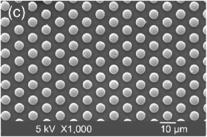
Chemical and/or geometrical surface modification affects the solid-liquid interactions. This offers a convenient control in surface physics. For example, physical roughness increases (decreases) the contact angle for hydrophobic (hydrophilic) substrates. Recently, superhydrophobic surfaces through controlled microstructures (see Fig. 1c) have been developed, advanced, and investigated for their water-repelling Onda et al. (1996); Richard et al. (2002); Lafuma and Quéré (2003) and hydrodynamic slip applications Steinberger et al. (2007); Lauga et al. (2007). A water droplet when deposited on a micropatterned hydrophobic surface can exhibit a metastable state of heterogeneously wetting with air trapped between the liquid and surface, forming a “Fakir” drop Quéré (2002, 2005). A spontaneous transition can occur from “Fakir” to homogeneously wetting “Wenzel” state with a smaller contact angle, even in the case of zero impact velocity Sbragaglia et al. (2007); Courbin et al. (2007). At the breakdown of superhydrophobicity, intriguing filling dynamics of water infiltration was found to possess multiple timescales and to tune the shape of the wetted areas by the geometric dimensions of the micropillars Pirat et al. (2008). In drop impact experiment, the threshold of the impact velocity marking the transition from Fakir to Wenzel state is found to depend on the geometric dimensions of the hydrophobic microstructures Reyssat et al. (2006); Hyväluoma and Timonen (2008). So far, geometric arrangements and the impact velocity have been the main control parameters for the drop impact onto superhydrophobic surfaces Richard and Quéré (2000); Bartolo et al. (2006). The change in surrounding air pressure has not yet been explored in this context. We will also study this effect here.
The analyzed superhydrophobic substrates consist of carbon nanofiber jungles. Carbon filaments are formed catalytically in metallic catalysts, particularly in Ni, Fe and Co based catalysts, used for the conversion of carbon containing gases, e.g. in steam reforming of hydrocarbons and Fischer-Tropsch synthesis Jong and Geus (2000). In these cases, the carbon filament formation was detrimental for operation as they plugged reactors and deactivated catalysts. Fiber type carbon nanomaterials can be classified into three types, namely, Carbon Nanofiber (CNF), Carbon Nanotube (CNT) and Single Walled Nanotube (SWNT). In CNF the graphitic planes are oriented at an angle to the central axis, thus exposing graphite edge planes. In CNT the graphitic planes run parallel to the central axis, in this state only basal planes are exposed. CNT is also referred to as Multi-Walled Carbon nanotubes (MWNT) or parallel carbon nanofibers. If the fiber consists of only one graphene sheet that is oriented in the direction parallel to the fiber axis, it is called a single-walled carbon nanotube. We refer the reader to Ref. Melechko et al. (2005); de Jong and Geus (2000); Rodriguez (1993) for the history, studies, and reviews of catalytically generated CNFs.
The diameters of CNFs, in general, range from a few to hundred nanometers and their lengths vary from micrometers to millimeters Melechko et al. (2005). The novel physical and chemical properties of CNFs include high surface areas, large elasticity, and low electrical resistivity and hence make CNFs good candidates for catalysts, catalyst supports, and selective adsorption sites Rodriguez (1993). Particularly, the highly porous layers of entangled nanofibers (CNF jungles) are suitable as catalyst supports for liquid phase reaction, allowing fast mass transfer to catalytic active particles deposited on the CNFs Ledoux and Pham-Huu (2005); Toebes et al. (2005). In this work entangled layers of CNFs are grown directly on iron and stainless steel metal foils, and we experimentally study the dynamical effect of water drop impinging upon these CNFs.
II Experimental Section
II.1 Superhydrophobic samples
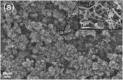
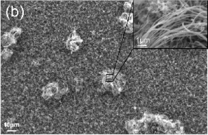
Our superhydrophobic substrates are catalytically synthesized CNFJs and micropatterned polymers. Fig. 1 shows representative scanning electron microscope (SEM) images of used samples. As revealed by Fig. 1 (a) and (b), catalytically generated CNFJs are composed of entangled and bundled carbon nano-filaments forming uncontrolled, microscopic roughness. In contrast, Fig. 1 (c) shows the top-view of an ordered, microstructured substrate comprising micro-pillars periodically placed in a structured lattice.
Synthesis of Carbon Nanofiber surfaces. The carbon nanofibers (CNFs) were produced by catalytic vapor deposition (CVD) from carbon containing gases using a metallic catalyst Rodriguez (1993). Two types of catalytic materials were employed: they are iron (, Alfa Aesar) and stainless steel Type 304 (Fe:Cr:Ni 70:19:11%, Alfa Aesar) foils of mm thick. Round samples of these metal foils ( mm in diameter) were prepared by an electric discharge wire-cutting machine (Agiecut Challenge 2, GF AgieCharmilles). The foils were degreased ultrasonically in acetone and dried at room temperature before loaded into the CVD chamber. In addition, hydrogen and nitrogen ( purity, Praxair), and ethylene (C2H4, purity, Praxair) were used for the CNF formation without further purification.
The CVD reactor consists of a vertical quartz reactor, with a porous quartz plate centrally placed to support the metal foils. The temperature was raised from room temperature to C at a rate of K/min. The samples were first pre-treated in a hydrogen/nitrogen mixture ( H2 with N2) with a total flow of for 1 hr at C. After the pre-treatment, ethylene was fed into the reactor (20% with N2/H2, ) at C for hrs (with stainless steel foil) or hrs (with iron foil). During the heating process at the high temperature, the decomposition of C2H4 led to the growth of carbon filaments upon the metallic catalysts. The concentration of hydrogen and the total flow were kept the same during pre-treatment and deposition. Finally the ethylene and hydrogen gas streams were shut off and the whole system was cooled down to room temperature under nitrogen at a rate of K/min.
Preparation of the polymeric microstructures. Micro-patterned substrates are composed of PDMS elastomer (Polydimethylsiloxance, RTV 615 rubber component A and curing agent B, GE Bayer Silicones). The fabrication of precise and controllable microstructures was achieved via a micro-molding method Vogelaar et al. (2006). This technique is to cast a polymeric film from solution on a molding wafer of desirable micropatterns. The PDMS films were obtained by mixing the rubber component A with the curing agent B (). The mixture was degassed and then poured onto the mold ( mm) and cured in an oven for hrs at C. The casting molds consisted of diverse arrays of micro-patterns, which can produce periodically arranged, round or rectangular polymeric micro-pillars of height , diameter or width , and the interspacing . With different lattice arrangements, , , and , we controlled the roughness of the polymeric microstructures. We characterize the surface roughness f by the ratio of the total surface area to that projected on the horizontal plane For the experiments presented here, , , and , and is varied between and . The corresponding f spans between and .
Contact Angle Measurements. The contact angle measurements were performed with a milli-Q water droplet of , matching the volume of impacting droplet of wide in radius, with the Laplace-Young fitting method (OCA 20, DataPhysics). Catalytically generated CNFJs exhibit random topography of multiscale roughness, and thus we need to ensure the homogeneous wettability of such surfaces when performing drop impact experiments. The static contact angle of CNFJs reported here was measured at different locations on the same sample, both before and after the drop impact experiment. The scattering of these data is used to estimate the error in .
II.2 Drop impact experiments
The general experimental procedure consists in releasing an impinging milli-Q water droplet from a fine needle ( mm inner diameter) with a syringe pump (PHD 2000 Infusion, Harvard Apparatus) at different heights to vary the impact speed upon the solid surface. The balance between the surface tension and droplet gravitational force sets the droplet size, which is mm in radius within deviation. The whole experimental setup was enclosed in a chamber, connected with a vacuum pump so as to control the pressure of the surrounding air. The dynamics of drop impact was recorded by a high-speed camera (Fastcam SA1, Photron) with a recording rate ranging from to fps (frames per second). The impact velocity and the droplet size were determined from the captured images.
Several control parameters influence the impact dynamics, for example, droplet size, liquid viscosity , impact velocity . We describe these effects in terms of dimensionless numbers: the Weber number , the ratio of kinetic energy to surface energy, characterizing the deformability of the droplet; the Reynolds number , the ratio of inertia to viscosity effect:
| (1) |
Here is the radius of the liquid drop, is the impact velocity, is the liquid density, is the surface tension, and is the liquid viscosity. In this paper, we did not simultaneously change and by using different liquids; instead, these parameters are only different ways to non-dimensionalize the velocity of a milli-Q water droplet. The Ohnesorge number, comparing viscous and capillary forces, Oh = is small in our experiments. In addition, we control and measure the pressure of the surrounding air, noted as . For the data presented here we specify the cases under reduced air pressure, otherwise at the standard ambient pressure.
III Results and Discussion
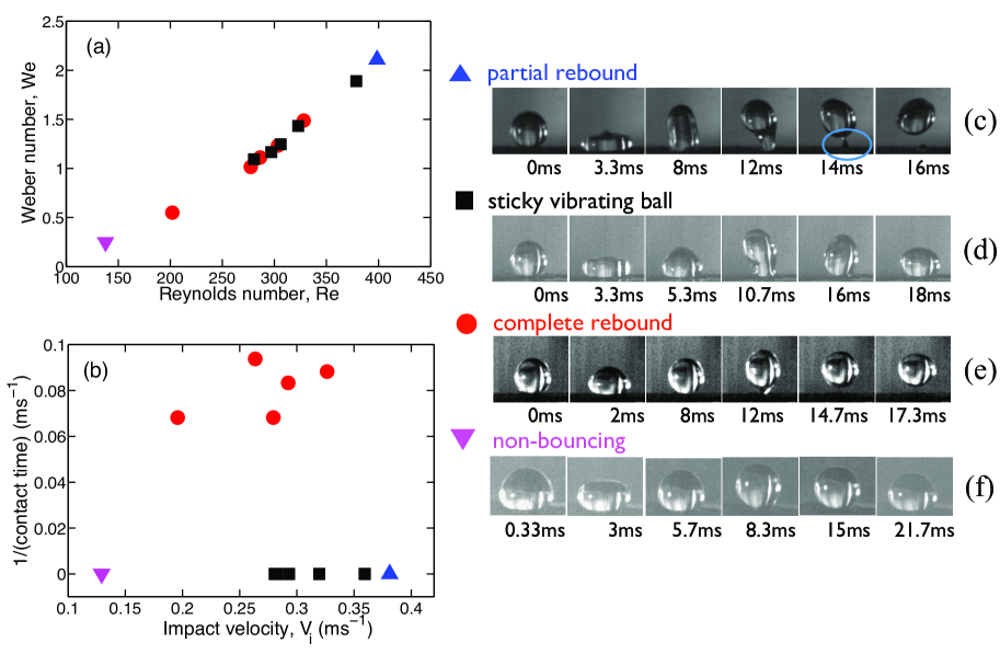
In this section, we compare impact events on CNFs and on microstructured surfaces with similar wettability. Fig. 2 shows a small fraction of the phase space and the time evolution of the impact dynamics for water drops impacting upon CNFJs of . In this small -number regime (), the impact events include non-bouncing Fakir droplet, complete rebound, sticky wetting ball, and partial rebound, generally in this sequence as is gradually increased. When a water droplet is gently deposited, due to small kinetic energy the droplet maintains in a Cassie-wetting “Fakir” state with air trapped underneath the drop and thus a high contact angle during the whole impacting process, as shown in Fig. 2f. In this heterogeneous state, air is trapped underneath the droplet and between the porous fibers. The non-wetting nature of the sample limits the spreading of the drop and sometimes even leads to a complete rebound (Fig. 2e). At high a wetting transition can occur as the kinetic energy overcomes the surface energy, associated with the liquid surface tension, and the droplet turns to the completely wetting Wenzel state, in which it is pinned on the surface (Figs. 2c and d).
The average contact time before the droplet bounces off the surface is (based on the marked data () in Fig. 2b). This average value is consistent with the value found by a recent study with a multiwalled carbon nanotube array with a static contact angle of Wang et al. (2007). The coexistence of different dynamical behaviors for illustrates the complexity of the impact process, showing the interplay of several parameters and indicating that other factors can affect the phase space. For instance, from our results we note that the complete rebound regime happens at higher between and for a more hydrophobic CNF substrate with a larger .
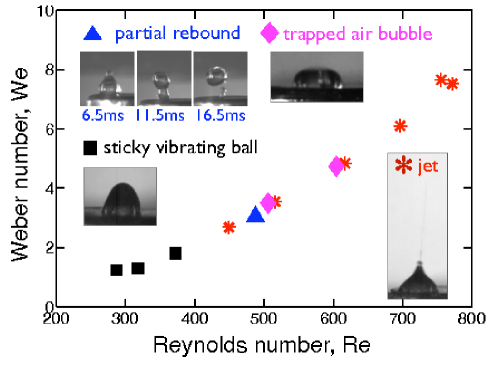

Fig. 3 shows the phase diagram for between and , corresponding to high , when a water droplet impacts upon a CNF surface of shown in Fig. 1b. In this -range, as discussed above, the impact scenario can display a complete bouncing or a pinning of contact line resulting in wetting. Also, trapping an air bubble or jetting can happen due to the development of an air cavity. Fig. 4 shows the detailed evolutions of (a) trapping an air bubble and (b) emitting a fast jet. For our -range between and , on impact a surface capillary wave is excited and the droplet deforms like a pyramid around ms. The oscillation of the surface deformation often makes a toroidal droplet producing a cylinder-like cavity; see the snapshot at in Fig. 4a and that at in Fig. 4b. Then the following dynamics of the cavity restoration determines the subsequent behaviors: in (a) at a lower the surface wave restores the top of cavity sooner and closes it up producing a residual void; in (b) at a higher the fast collapse of the cavity produces a fast jet. Our data reveal that the shooting jets can be as fine as in radius and as fast as . Similar observations underlying the same mechanism have recently been investigated with ordered, superhydrophobic microstructures for the -number ranging between and Bartolo et al. (2006). The analogy of the impact phenomena suggests that the formation and the collapse of the air cavity may be insensitive to the details of surface roughness.
In the higher -number range (between and ) splashing impacts occur as shown by Fig. 5 for CNFs. Here, the “splashing” phenomenon refers to the formation of many satellite droplets, which merge during the spreading and/or contracting stages of the water film from our observations. In Fig. 5a under , at 1 ms tiny droplets radially emit while the water sheet still spreads outwards with wavy perturbations, resembling “fingers”, at the edge of water film. Several droplets originated from the wavy perimeter develop between and while the main water sheet contracts, shaping into a partial rebound. A similar splashing phenomenon has lately been observed at with a superhydrophobic surface consisting of regular micro-pillars of in height, and in the interspacing distance between pillars Reyssat et al. (2006). This Ref. also reports that the critical -number above which droplets eject is about for a flat hydrophobic solid and no fragmentation of droplets even at for a flat hydrophilic solid. With these observations, the authors conjecture that the role of the film of air plays a crucial role because the non-wetting Fakir state promotes an air film for superhydrophobic solids. However, our investigations find the effect of air pressure on the splashing to be negligible in this parameter regime; Fig. 5b reveals the same kind of splashing at a low air pressure, , with similar and to those in Fig. 5a. Our experiments at different with similar numbers resemble the same type of splashing. Hence, the data suggest that the mechanism of aforementioned splashing behaviors is due to the effect of surface roughness, and not due to the surrounding air.
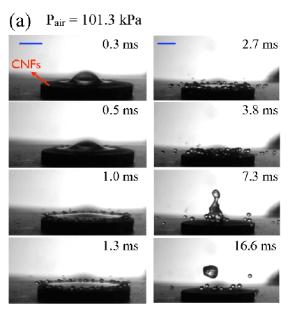
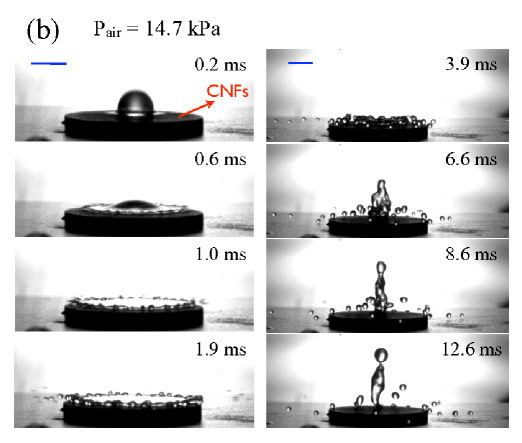
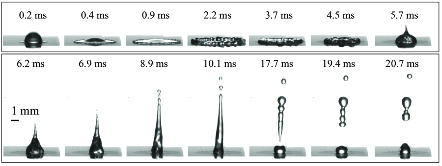
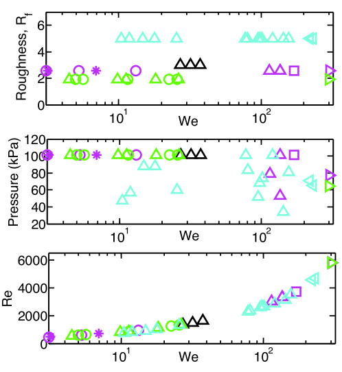
Fig. 6 shows a partial rebound for an impacting drop, with similar control parameters , and , but now for a polymeric microstructured surface consisting of round pillars of , and . As observed from the snapshots, the rim is not destabilized in the same way as for the unstructured CNFJs (compare Fig. 5 and 6 at ). Instead of perimetric fingers, wavy bumps develop and eventually merge together at the center to form an elongating water fountain. The pinning of the water wets the microstructured surface and breaks the fountain while surface tension is in action, resulting in a few breaking-up droplets. Consistent with the results in Ref. Reyssat et al. (2006), our experiment at , and shows that a few () satellite droplets develop during the contraction of the water sheet upon a micropatterned substrate of , and with a roughness f. The comparisons between these different experiments reveal that roughness has a profound effect on splashing impacts. In addition, the multiscale, uncontrolled surface roughness of CNFs display pronounced formations of satellite droplets, comparable with the impacts upon ordered micropatterned substrates under alike parameters. This finding suggests that the smaller length scale of carbon fibers may enhance the instability of perimetric wavy fingers and thus produce stronger fragmentations.
Fig. 7 displays the phase space of water impact dynamics onto polymeric microstructures of explored at different air pressure . Different colors depict different surface roughness f controlled by the geometric arrangement of micropillars of . Similar impact phenomena to those upon CNFs are observed, including jetting, complete rebound, and partial rebound for small . For partial rebound occurs with a high deformability stretching the water droplet into a elongating column. As discussed in Ref. Reyssat et al. (2006), a threshold of impact velocity marking a transition from complete bouncing to wetting or partially pinned drop is identified as a function of the size of the superhydrophobic microtextures. Interestingly, for the small roughness f , we observe coexistence of different dynamical processes in some range of impact velocities. At large (between and ) a few satellite droplets form while the main impact can partially rebound () or behave like a sticky wetting ball (shown by ).
IV Conclusions
In comparison with the drop impacts performed upon microstructured hydrophobic surfaces, for and under the atmospheric pressure impacts upon CNFs of multiscale roughness reveal similar dynamical behaviors including Cassie-wetting Fakir droplet, complete rebound, partial rebound, jetting, and trapping bubbles. This comparison implies that impact evolutions are insensitive to the details of the roughness of superhydropohobic surfaces at small -number. Rather than a bouncing-pinning transition, driven by a threshold of impact velocity, as described in Ref Reyssat et al. (2006) for regular microstructures, we noticed the coexistence of complete rebound and sticky wetting droplet for CNFs at . This observation indicates that the details of roughness can influence the transitional boundary in the phase space of impact events.
Partial rebounds occur in the -range between and for water drops hitting upon micropatterned substrates with and a roughness ranging from to . Air pressure and the surface roughness have hardly any effect in this partially rebouncing regime. At higher , profound splashing impacts forming several satellite droplets take place for superhydrophobic CNFs. This splashing mechanism is not suppressed by the decrease in air pressure, which was found to debilitate the corona splashing on smooth wetting surfaces Xu et al. (2005, 2007). Beyond , in contrast to the violent splashing events on the rough CNFJs, on imcrostruture substrates the fragmentation is much less pronounced, revealing the importance of sub-micron roughness for splashing.
V Acknowledgments
The authors thank Alisia M. Peters and Hrudya Nair for their helps on the preparations of the polymeric microstructures. We also gratefully acknowledge the Membrane Science and Technology Group at the University of Twente for the usage of the contact angle measurement device.
References
- Yarin (2006) A. L. Yarin, Annu. Rev. Fluid Mech. 38, 159 (2006).
- Quéré (2008) D. Quéré, Ann. Rev. Materials Research 38, 71 (2008).
- Richard and Quéré (2000) D. Richard and D. Quéré, EPL 50, 769 (2000).
- Richard et al. (2002) D. Richard, C. Clanet, and D. Quéré, Nature 417, 811 (2002).
- Biance et al. (2004) A. L. Biance, C. Clanet, and D. Quéré, Phys. Rev. E 69, 016301 (2004).
- Bartolo et al. (2006) D. Bartolo, C. Josserand, and D. Bonn, Phys. Rev. Lett. 96, 124501 (2006).
- Reyssat et al. (2006) M. Reyssat, A. Pépin, F. Marty, Y. Chen, and D. Quéré, EPL 74, 306 (2006).
- Jung and Bhushan (2008) Y.-C. Jung and B. Bhushan, Langmuir 24, 6262 (2008).
- Hyväluoma and Timonen (2008) J. Hyväluoma and J. Timonen, EPL 83, 64002 (2008).
- Xu et al. (2005) L. Xu, W. W. Zhang, and S. R. Nagel, Phys. Rev. Lett. 94, 184505 (2005).
- Xu (2007) L. Xu, Phys. Rev. E 75, 056316 (2007).
- Xu et al. (2007) L. Xu, L. Barcos, and S. R. Nagel, Phys. Rev. E 76, 066311 (2007).
- Onda et al. (1996) T. Onda, S. Shibuichi, N. Satoh, and K. Tsujii, Langmuir 12, 2125 (1996).
- Lafuma and Quéré (2003) A. Lafuma and D. Quéré, Nat. Mater. 2, 457 (2003).
- Steinberger et al. (2007) A. Steinberger, C. Cottin-Bizonne, P. Kleimann, and E. Charlaix, Nature Materials 6, 665 (2007).
- Lauga et al. (2007) E. Lauga, M. P. Brenner, and H. A. Stone, Microfluidics: The No-Slip Boundary Condition (Springer, New-York, 2007), chap. 19.
- Quéré (2002) D. Quéré, Nat. Mater. 1, 14 (2002).
- Quéré (2005) D. Quéré, Rep. Prog. Phys. 68, 2495 (2005).
- Sbragaglia et al. (2007) M. Sbragaglia, A. M. Peters, C. Pirat, B. M. Borkent, R. G. H. Lammertink, M. Wessling, and D. Lohse, Phys. Rev. Lett. 99, 156001 (2007).
- Courbin et al. (2007) L. Courbin, E. Denieul, E. Dressaire, M. Roper, A. Ajdari, and H. A. Stone, Nat. Mater. 6, 661 (2007).
- Pirat et al. (2008) C. Pirat, M. Sbragaglia, A. M. Peters, B. M. Borkent, R. G. H. Lammertink, M. Wessling, and D. Lohse, EPL 81, 66002 (2008).
- Jong and Geus (2000) K. P. D. Jong and J. W. Geus, Catal. Rev. Sci. Eng. 42, 481 (2000).
- Melechko et al. (2005) A. V. Melechko, V. I. Merkulov, T. E. McKnight, M. A. Guillorn, K. L. Klein, D. H. Lowndes, and M. L. Simpson, J. Appl. Phys. 97, 041301 (2005).
- de Jong and Geus (2000) K. P. de Jong and J. W. Geus, Catal. Rev. Sci. Eng. 42, 481 (2000).
- Rodriguez (1993) N. M. Rodriguez, J. Mater. Res. 8, 3233 (1993).
- Ledoux and Pham-Huu (2005) M. J. Ledoux and C. Pham-Huu, Catal. Today 102–103, 2 (2005).
- Toebes et al. (2005) M. L. Toebes, T. A. Nijhuis, J. Hájek, J. H. Bitter, A. J. van Dillen, D. Y. Murzin, and K. P. de Jong, Chem. Eng. Sci. 60, 5682 (2005).
- Vogelaar et al. (2006) L. Vogelaar, R. G. H. Lammertink, and M. Wessling, Langmuir 22, 3125 (2006).
- Wang et al. (2007) Z. Wang, C. Lopez, A. Hirsa, and N. Koratkar, Appl. Phys. Lett. 91, 023105 (2007).