Amplitude and phase modulation of time-energy entangled two-photon states
F. Zäh1, M. Halder2, and T. Feurer1
1University of Bern, Institute of Applied Physics, Sidlerstr. 5, 3012 Bern, Switzerland 2Université de Genve, GAP-Optique, Rue de l’École-de-Médecine 20, 1211 Genve, Switzerland
florian.zaeh@iap.unibe.ch
Abstract
We experimentally demonstrate amplitude and phase modulation of a time-energy entangled two-photon wave function. The entangled photons are produced by spontaneous parametric down-conversion, spectrally dispersed in an prism compressor, modulated in amplitude and/or phase, and detected in coincidence by sum-frequency generation. First, we present a Fourier optical analysis of the optical setup yielding an analytic expression for the resulting field distribution at the exit plane of the shaping apparatus. We then introduce amplitude and/or phase shaping and present results which can only be obtained through a combination of the two. Specifically, we use a shaper-based interferometer to measure the two-photon interference of an almost bandwidth-limited two-photon wave function.
OCIS codes: (190.4223) Nonlinear wave mixing; (320.5540) Pulse shaping, (270.5570) Quantum detectors.
References and links
- [1] E. Schrödinger, ”Die gegenwärtige Situation in der Quantenmechanik,” Naturwissenschaften 23, 807–812, 823–828, 844–849 (1935)
- [2] S. Popescu, and D. Rohrlich, ”The joy of entanglement,” in Introduction to quantum computation and information, H.-K. Lo, S. Popescu, T. Spiller, eds. (World Scientific, 1998), pp. 29–48
- [3] N. Gisin, and R. Thew, ”Quantum communication,” Nature Phot. 1, 165–171 (2007)
- [4] D. Bouwmeester, A. Ekert, and A. Zeilinger The Physics of Quantum Information (Springer, 2000)
- [5] D.C. Burnham, and D.L. Weinberg, ”Observation of simultaneity in parametric production of optical photon pairs,” Phys. Rev. Lett. 25, 84–87 (1970)
- [6] Z.Y. Ou, and L. Mandel, ”Violation of Bell’s inequality and classical probability in a two-photon correlation experiment”, Phys. Rev. Lett. 61, 50–53 (1988)
- [7] Y.H. Shih, and C.O. Alley, ”New type of Einstein-Podolsky-Rosen-Bohm experiment using pairs of light quanta produced by optical parametric down conversion,” Phys. Rev. Lett 61, 2921–2924 (1988)
- [8] A.A. Malygin, A.N. Penin, A.V. Sergienko, ”Absolute calibration of the sensitivity of photodetectors using a biphotonic field , Sov. Phys. JETP Lett. 33, 477–480 (1981)
- [9] P.G. Kwiat, A.M. Steinberg, R.Y. Chiao, P.H. Eberhard, and M.D. Petroff, ”High-efficiency single-photon detectors,” Phys. Rev. A 48, 867–870 (1993)
- [10] R. Ghosh, and L. Mandel, ”Observation of nonclassical effects in the interference of two photons,” Phys. Rev. Lett. 59, 1903–1905 (1987)
- [11] P.G. Kwiat, W.A. Vareka, C.K. Hong, H. Nathel, and R.Y. Chiao, ”Correlated two-photon interference in a dual-beam Michelson interferometer,” Phys. Rev. A 41, 2910–2913 (1990)
- [12] D.V. Strekalov, A.V. Sergienko, D.N. Klyshko, and Y.H. Shih, ”Observation of Two-Photon ”Ghost” Interference and Diffraction,” Phys. Rev. Lett. 74, 3600–3603 (1995)
- [13] T.B. Pittman, Y.H. Shih, D.V. Strekalov, and A.V. Sergienko, ”Optical imaging by means of two-photon quantum entanglement,” Phys. Rev. A 52, 3429–3432 (1995)
- [14] J. Jacobson, G. Björk, I. Chuang, and Y. Yamamoto, ”Photonic de Broglie waves,” Phys. Rev. Lett. 74, 4835–4838 (1995)
- [15] A.N. Boto, P. Kok, D.S. Abrams, S.L. Braunstein, C.P. Williams, and J.P. Dowling, ”Quantum interferometric optical lithography: exploiting entanglement to beat the diffraction limit,” Phys. Rev. Lett. 85, 2733–2736 (2000)
- [16] C.K. Hong, Z.Y. Ou, and L. Mandel ”Measurement of Subpicosecond Time Intervals between Two Photons by Interference,” Phys. Rev. Lett. 59, 2044–2046 (1987)
- [17] J. D. Franson, ”Bell inequality for position and time,” Phys. Rev. Lett. 62, 2205–2208 (1989)
- [18] Z.Y. Ou, and Y.J. Lu, ”Cavity enhanced spontaneous parametric down-conversion for the prolongation of correlation time between conjugate photons,” Phys. Rev. Lett. 83, 2556–2559 (1999)
- [19] M. Bellini, F. Marin, S. Viciani, A. Zavatta, and F.T. Arecchi, ”Nonlocal Pulse Shaping with Entangled Photon Pairs,” Phys. Rev. Lett. 90, 043602 (2003)
- [20] S. Viciani, A. Zavatta, and M. Bellini, ”Nonlocal modulations of the temporal and spectral profiles of an entangled photon pair,” Phys. Rev. A 69, 053801 (2004)
- [21] B. Dayan, A. Pe’er, A.A. Friesem, and Y. Silberberg, ”Nonlinear Interactions with an Ultrahigh Flux of Broadband Entangled Photons,” Phys. Rev. Lett. 94, 043602 (2005)
- [22] B. Dayan, A. Pe’er, A.A. Friesem, and Y. Silberberg, ”Temporal Shaping of Entangled Photons,” Phys. Rev. Lett. 94, 073601 (2005)
- [23] G.D. Boyd, and D.A. Kleinman, ”Parametric Interaction of Focused Gaussian Light Beams,” J. Appl. Phys. 39, 3597–3639 (1968)
- [24] A.M. Weiner, ”Femtosecond pulse shaping using spatial light modulators,” Rev. Sci. Instrum. 71, 1929–1960 (2000)
- [25] J.C. Diels, and W. Rudolph, Ultrashort Laser Pulse Phenomena (Academic Press, 1996)
- [26] T.E. Keller, and M.H. Rubin, ”Theory of two-photon entanglement for spontaneous parametric down-conversion driven by a narrow pump pulse,” Phys. Rev. A 56, 1534–1541 (1997)
- [27] B. Dayan, Y. Bromberg, I. Afek, and Y. Silberberg, ”Spectral polarization and spectral phase control of time-energy entangled photons,” Phys. Rev. A 75, 043804 (2007)
1 Introduction
Entangled photon states are ideal subjects to study nonlocal interactions and applications in quantum communication or quantum information processing [1, 2, 3, 4]. A convenient way to produce such states is through spontaneous parametric down-conversion (SPDC). An intense pump beam creates a second order nonlinear response strong enough to facilitate the annihilation of a pump photon and the creation of a pair of down-converted photons. In a type-I process the photon pairs consist of a signal and an idler photon and show entanglement with respect to space-wave vector and time-energy [5]. In the past these photon pairs have been used for example to demonstrate the violation of Bell’s inequality [6, 7], to absolutely calibrate single photon counters [8, 9], to demonstrate the appearance of fourth order interference in absence of second order interference [10, 11], to explore two-photon imaging [12, 13, 14, 15], or to investigate fundamental properties of entangled photon pairs [5, 16, 17, 18]. Recently, it was demonstrated that the visibility of a fourth order interferogram of the idler beam can be affected by a spectral bandpass filter in the signal beam [19, 20], and that the quantum state of a photon pair can be phase-modulated in the same way as coherent classical light pulses are tailored [21, 22]. In order to affirm the effect of phase modulation on the two-photon wave function, coincidences were detected through sum-frequency generation. This detection scheme has a rather low efficiency but became viable because the short coherence time of the photon pairs allowed for a high flux while remaining in the single photon limit [21, 22].
Here, we use a very similar setup as the one presented by Silberberg and coworkers [21] but extend phase-only shaping of the spectral components to phase and/or amplitude shaping. First, we present a Fourier-optical analysis of the optical setup and give an analytic expression for the field distribution at the exit plane of the shaping apparatus which also coincides with the position of the coincidence detection. This result is subsequently used to simulate all experimental results. We then proceed by demonstrating the increased versatility of the setup for example by measuring the second order interferogram of a bandwidth-limited two-photon wave function through a shaper-based interferometer.
2 Experimental realization
The experimental setup was similar to that reported by the Silberberg group [21]. The entangled photon pairs were created through SPDC of a continuous wave 532 nm single-mode pump laser in a temperature stabilized, periodically poled KTiOPO4 (PPKTP) crystal. Both photons had the same polarization and the entanglement was with respect to time-energy. The spectral bandwidth of the pump laser was approximately 5 MHz and the maximum pump power 5 W. Given a poling periodicity of 9 m, phase matching allowed for generating an approximately 50 nm broad spectrum centered at twice the pump wavelength. The exact shape and bandwidth of the spectrum was dominated by the crystal temperature. Here, the temperature was set to 29.5 ∘C maximizing the spectral bandwidth as well as the conversion efficiency, which was on the order of . The focusing lens for the pump laser was selected according to the optimum focusing condition [23] and had a focal length of 150 mm. The emerging photon pairs were imaged to an intermediate plane and from there to a second PPKTP crystal. Both imaging sections included a two-prism combination, first, to spectrally disperse the down-converted spectrum at the intermediate plane and, second, to compensate for any second order dispersion in the setup. A computer-controlled spatial light modulator (JenOptik SLM 640-d) was placed at the intermediate plane and modulated the amplitude and the phase of selected spectral components. The modulated spectrum was recombined in the second crystal where it generated sum-frequency photons with a maximum efficiency on the order of . A spectral filter (4mm BG18) suppressed the remaining photon pairs and the sum-frequency photons were collected by a multi-mode fiber connected to a single-photon counter (PerkinElmer SPCM-AQR-15). Its efficiency at 532 nm is about 33 times higher than at 1064 nm. Detecting the sum-frequency photons was essentially similar to a coincidence detection scheme with an extremely high temporal resolution [21]. Almost all measurements used an integration time between 5 s and 100 s and the dark count rate was approximately 60 cps. In order to verify that the detector was measuring sum-frequency photons at 532 nm rather than residual photons around 1064 nm we increased the temperature of the second crystal by a few degrees, thus detuning the acceptance function of the sum-frequency crystal, and observed that the count rate dropped down to the dark count rate.
Because the optical setup is quite different from standard 4f-type geometries [24] we first present a detailed Fourier optical analysis. We use the paraxial approximation and assume that the optical axis is parallel to the axis. It is sufficient to treat the problem in one dimension, , as the other dimension, , remains unaffected by the prism pairs. We use the transfer functions for free-space propagation , for an ideal lens , and for a prism in minimum deviation geometry , with the center frequency of the optical wavepacket , its center wavelength , and .
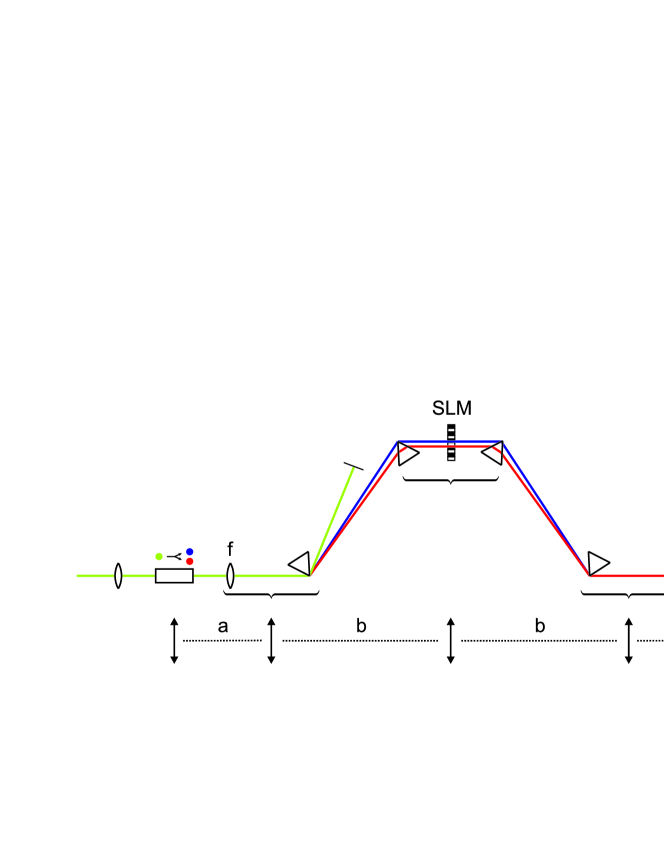
Figure 1 shows a schematic of the setup. Both imaging lenses have a focal length of and the distances crystal–lens and lens–SLM are and , respectively, yielding a magnification of . Without loss of generality, we assume that the first prism follows immediately after the imaging lens and the second prism is located right before the intermediate SLM plane. Then, we find for a classical light field in the last image plane, i.e. at the position of the up-conversion crystal
| (1) |
with the electric field at the origin and the wave vector . Note that the size and position of the resulting field are independent of the phase and amplitude modulation applied, however, the spectral modulation is a function of space and a curved phase is introduced. The first term of the exponential function specifies a quadratic spatial phase which is related to the imaging geometry. The second part is quadratic in and reflects the group velocity dispersion of the four prism arrangement. Keeping in mind that the distance between the two prisms is and inserting the explicit expression for , it is easy to show that the quadratic phase corresponds to the second order Taylor coefficient of a regular prism compressor [25]. In our setup the distance between the two prisms is adjusted such that all positive dispersion present in the optical setup is compensated for and the net dispersion is zero. The argument of the modulator’s transfer function depends both on and , which is a consequence of space-time coupling. The frequency-to-space mapping is given by . Assuming that the incoming field may be decomposed into a spatial and a spectral part and, further, that only space averaged fields are measured yields
| (2) |
with
| (3) |
3 Quantum optical description of the measurement
In the following section we briefly review the wave function which replaces the classical field in Eq. 2 and which is modulated by a specific modulator transfer function . While the pump field is treated classically, the signal and the idler fields are quantized. Signal and idler photons have the same polarization and, thus, experience the same index of refraction. The two-photon wave function generated in SPDC has been derived in reference [26] with first order perturbation theory. In all experiments reported here, the frequency resolution at the intermediate plane rather than the bandwidth of the pump laser limits the coherences observed, that is, the pump field can be approximated by a monochromatic field with a frequency and the two-photon wave function is
| (4) |
with
| (5) |
All constants and slowly varying dependencies are combined in , is the phase mismatch, and the length and the periodicity of the periodically poled crystal. The sum-frequency signal measured after the second crystal is proportional to the second order coherence function assuming that for a perfectly aligned setup there is no delay between the signal and the idler photon. That is, the coincidence rate is given by
| (6) |
If the pulse shaper is used then .
4 Experimental results
All experiments presented in the following were simulated by numerically solving Eq. 6 with the appropriate modulator transfer function Eq. 3. The simulations take into account the pixelated nature of the SLM used and assume an uncertainty of the temperature of K and of the beam waist of %.
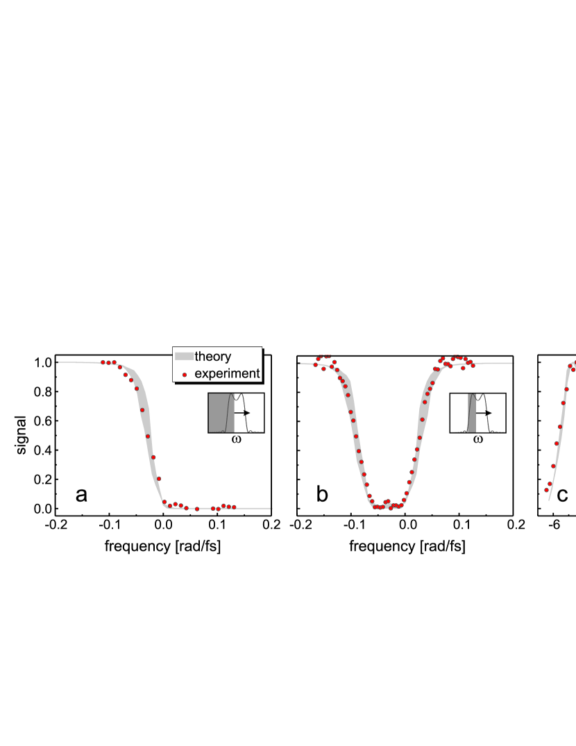
First, we present three different pure amplitude-only modulation experiments which imply . Figure 2(a) shows the signal versus the position of a spectral edge filter. By moving the edge filter across the spectrum more and more frequencies are blocked and the signal drops to zero. Note that zero signal is reached exactly when one half of the spectrum is blocked; in other words, removing all idler photons from all photon pairs is sufficient to destroy all coincidences measured at the second crystal. When only a spectral slice is blocked and scanned across the spectrum, the signal drops to a minimal value, exhibits a small peak around the center frequency, and then increases back to the initial value, as shown in Fig. 2(b). The signal is minimal when either most of the idler or most of the signal photons are blocked. The height and shape of the central peak depend on the width of the spectral block compared to the spectrum. Here, the spectral block is almost half as wide as the spectrum and, consequently, the peak is barely visible. Figure 2(c) shows the signal as a function of the position of an amplitude grating. The signal exhibits the same periodicity as the grating, is zero when the grating is asymmetric and maximal when the grating is symmetric with respect to the center frequency. In the asymmetric case the idler photons of one half of all photon pairs and the signal photons of the other half of all photon pairs are blocked causing the overall coincidence signal to disappear. Although the overall number of photons has been reduced by only one half, the signal is zero because not a single photon pair is left intact. In the symmetric case the amplitude grating blocks all idler and all signal photons of the same photon pairs, but passes all other photon pairs unaffected.
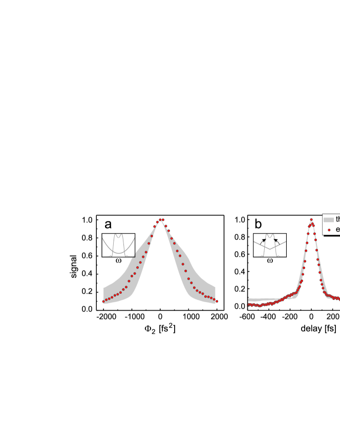
For pure phase modulations the amplitude of the modulator transfer function is . Various phase-only modulation examples have already been published by the Silberberg group [21, 22, 27] and two examples are shown in Fig. 3. When the phase modulation is quadratic in frequency, i.e. , the two-photon wave function is smeared out in time. In such a broadened two-photon wave function the chances for a coincidence are reduced resulting in a decreasing signal with increasing , as seen in Fig. 3(a). The result is similar for the classical light field of a coherent short pulse. Observing the maximum signal at confirms that the four-prism arrangement has been aligned such that it compensates for all positive quadratic dispersion. Next, we apply a V-shaped phase modulation. Such a phase modulation was already used in reference [21] and it shifts the idler photon with respect to the signal photon and samples the amplitude of the Fourier transform of . From the result presented in Fig. 3(a) we can deduce a coherence time of the two-photon wave function of approximately 150 fs. In both experiments the theoretical predictions agree well with the experimental results.
The last experiment requires simultaneous amplitude and phase shaping and our intention is to demonstrate a pulse shaper based unbalanced interferometer in front of the coincidence detector and to measure the two-photon interference. For a standard unbalanced interferometer, i.e. a Michelson or a Mach-Zehnder interferometer, the transfer function is
| (7) |
with the reflectivity and the transmission of the beamsplitter and the time delay . A pulse shaper allows mimicking a much more flexible transfer function, such as
| (8) |
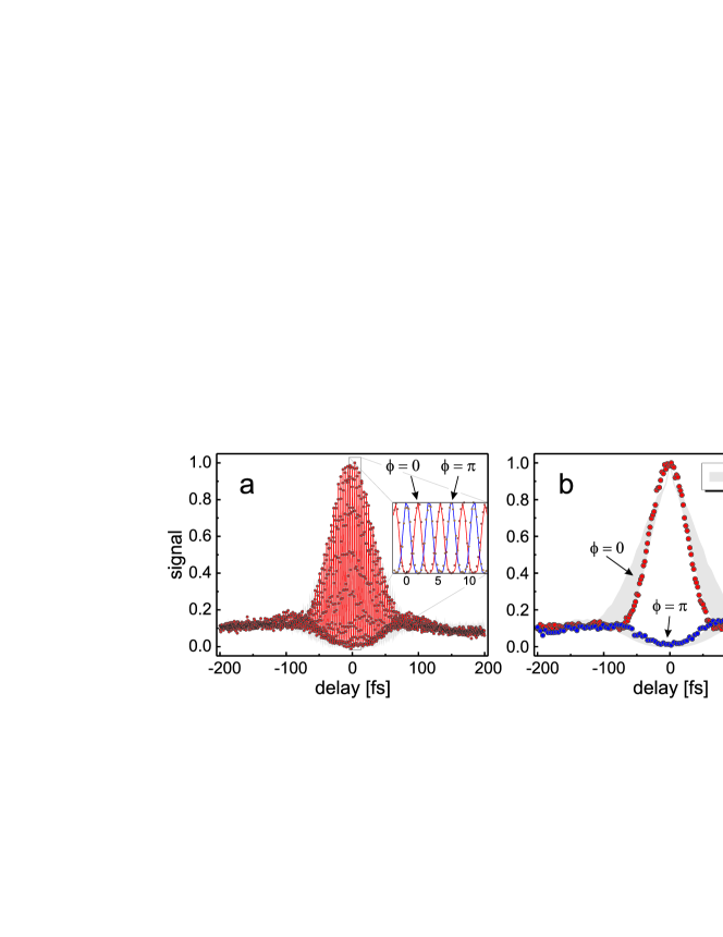
We see that for and eq. 8 resembles eq. 7 and an unbalanced Michelson interferometer may be simulated. The measured coincidence rate versus time delay, i.e. the two-photon interference, for and is shown Fig. 4(a). The signal oscillates with a periodicity that is determined by the frequency . The inset indicates that by selecting or allows to switch between the two output ports of the simulated interferometer; the two signals are exactly half a period out of phase. In order to measure these two signals with a real Michelson interferometer would require to move the coincidence detection apparatus from one exit port of the beam splitter to the other. If we select , only the slowly varying amplitudes of the signal and idler photons are delayed in time leaving their carrier frequencies unaffected. The results change quite dramatically, i.e. the oscillations completely disappear, as seen in Fig. 4(b). The results in Fig. 4(b) are especially interesting, because the two curves can readily be used to extract the fringe visibility as a function of time delay. From both measurements we can extract the coherence properties of the two-photon wave function, which must be close to bandwidth-limited because all second order dispersion has been compensated for.
5 Conclusion
We have presented a Fourier-optical analysis of the shaping setup first introduced to shaping of two-photon wave functions by the Silberberg group. By extending phase-only modulation to phase and amplitude modulation we have shown that a much larger variety of transfer functions can be realized. Specifically, we demonstrated a shaper-assisted unbalanced Michelson interferometer without any moving parts and measured the two-photon interference with it. With all second order dispersion removed by the four prism arrangement the coherence properties should be close to bandwidth limited. Lastly, we have demonstrated a measurement that cannot be obtained with a mechanical unbalanced Michelson interferometer and which yields and ’oscillation-free’ two-photon interference from which the fringe visibility can be readily derived.
Acknowledgments
We thank A. Pe’er, B. Dayan, and Y. Silberberg for many discussions. This work was supported by NCCR Quantum Photonics, research instrument of the Swiss National Science Foundation.