Simulational nanoengineering: Molecular dynamics implementation of an atomistic Stirling engine
Abstract
A nanoscale-sized Stirling engine with an atomistic working fluid has been modeled using molecular dynamics simulation. The design includes heat exchangers based on thermostats, pistons attached to a flywheel under load, and a regenerator. Key aspects of the behavior, including the time-dependent flows, are described. The model is shown to be capable of stable operation while producing net work at a moderate level of efficiency.
pacs:
05.70.Ln, 47.61.-k, 02.70.NsThe Stirling engine, an external combustion engine invented almost two centuries ago, and an early competitor of the steam engine, continues to attract interest owing to its potential effectiveness as a power source and its success in specialized applications Urieli and Berchowitz (1984); West (1986); Zemansky (1968). The underlying thermodynamic cycle consists of four stages: low-temperature isothermal compression of the working fluid, constant-volume displacement of the fluid between the cold and hot spaces of the engine with (optionally) the fluid gaining heat while passing through a heat-storing regenerator, high-temperature isothermal expansion, and constant-volume displacement between the hot and cold spaces with heat being returned to the regenerator. The net work is the excess energy produced by the expanding hot fluid over that needed to recompress the cold fluid. Unlike internal combustion engines, there is complete flexibility as to fuel type, including even solar energy; the fact that the complexities of combustion Manley et al. (2008) are avoided makes the Stirling engine an attractive candidate for simulation.
This paper describes the molecular dynamics (MD) simulation of a simplified Stirling engine using a discrete-particle working fluid. MD Alder and Wainwright (1957); Rahman (1964); Rapaport (2004) provides the capability for direct atomistic modeling of nanomachinery, together with the accompanying complex thermodynamic and fluid-dynamic processes. While past MD studies have included instances of heat production as a byproduct of work, e.g., in fracture Holian and Ravelo (1995), Taylor–Couette flow Hirshfeld and Rapaport (1998) and fluid jets Moseler and Landman (2000), the present simulations extend the scope of MD to systems that harness thermal energy for producing useful work111Thermodynamics was developed to explain the engines of the industrial revolution, statistical mechanics provides the atomistic basis for equilibrium thermodynamics, and MD addresses nonequilibrium phenomena beyond the scope of statistical mechanics; the present study revisits the original problem with a mechanical perspective..
The model engine incorporates a number of features: pistons driven by collisions with the fluid atoms, heat input and output controlled by thermostats that maintain isothermal conditions in the hot and cold spaces, a rotating flywheel connected to the pistons and subject to an applied load, and an atomistic regenerator intended to reduce heat wastage. The working fluid experiences substantial temperature and pressure variation over the cycle, but its thermodynamic and heat/mass transport properties are intrinsic to the atomistic model. This represents an advantage of MD over the alternative continuum-based analysis Martini (1983) where such details must be provided separately; if these and subsequent more extensive studies can be quantitatively validated, the role of MD in nanoengineering is assured.
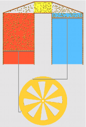
There are different Stirling engine designs, each involving engineering considerations that are not addressed here. It is the two-piston alpha version, shown in Fig. 1, that is modeled (the beta version, with a single piston and a mechanical displacer, is one of the alternatives). Even though the simulations consider a system that is an idealization of a real Stirling engine, its relative complexity – by MD standards – calls for several implementation decisions, with the goal of achieving a simple but reasonably complete operational model. The two-dimensional case is considered for convenience.
The atoms of the working fluid are soft-disk particles, interacting through a short-range potential with (condensation is avoided since there is no attraction); similar disks line the fixed engine walls and the moving piston faces. The linkages connecting the pistons to the flywheel ensure sinusoidal piston motion, but are idealized since the transverse parts are of variable length; the phase angle between the pistons is fixed at . The fluid atoms and movable engine components obey Newtonian dynamics; the force evaluation and solution of the equations of motion employ standard MD techniques Rapaport (2004).
In reduced MD units, the model engine has stroke , where is the flywheel radius and bore 67.7 (in MD units where, typically, corresponds to a length unit of 3.4Å, to a time unit of 2.16 psec if fluid atoms have mass , and defines temperature); the actual value of amounts to a mere 191Å. The working fluid contains atoms; this ‘large’ system is the main focus of the analysis, but a half-size ‘small’ system (shown in Fig. 1) with is also considered. The minimal size enables runs of adequate length without excessive computation, while demonstrating the extreme scales at which behavior remains reasonable.
Heat exchangers responsible for thermal input and output are modeled using thermostats. These act separately over the hot and cold spaces swept by the pistons, are applied every time step, and entail rescaling the velocities of all the fluid atoms in each space, after allowing for the current average flow. Use of thermostats, rather than thermalizing walls, prevents temperature fluctuations and enhances heat transfer (since unrestricted transfer rates from and to exogenous heat reservoirs are implied).
The flywheel phase angle is defined so that the hot piston is at its top position when . Average fluid density , where is the area occupied by the fluid, varies between 0.256 and 0.085, corresponding to a 3.03:1 compression ratio. The inertial contribution of the drive mechanism is assigned to the flywheel, with pistons and linkages assumed massless. The flywheel moment of inertia ; for density the rotation speed is low enough that piston speeds () are typically an order of magnitude less than the mean thermal velocity of the fluid atoms (the resulting slow fluid flow justifies the thermostat implementation). The flywheel kinetic energy also exceeds that of the fluid by a similar factor, ensuring minimal fluctuations in .
The role of the regenerator was recognized by its inclusion in the early Stirling design. Although not essential for operation, its function is to improve heat utilization by extracting heat from the hot fluid as it flows to the cold space and returning it when flow is reversed; typically implemented as a metallic mesh, it also impedes the flow. The model regenerator is assembled from atoms with , tethered to a uniform grid by a potential , where is the distance from the relevant grid site. Transiting fluid atoms collide with the (unthermostatted) tethered atoms and heat is transferred to or from the regenerator, depending on the relative temperatures; the heavier atoms undergo limited, relatively slow motion, but the contribution to performance in terms of heat storage is minimal since, to lessen flow impedance, . The area occupied by the regenerator is connected to the hot and cold spaces by triangular ducts.
Work is performed against an applied torque load , with . There is no energy loss due to the rough boundary walls since all collisions are elastic (energy is conserved when thermostats and load are removed). Temperature in the hot space is a parameter, and the cold space is fixed at unity. The system is started at maximum compression with the pistons at equal height () and rotation speed . Run length is time steps (of size 0.005), so while all runs cover the same time period, the number of cycles differs.


The principal outcome of the present simulations is a demonstration of the operational capability of the engine. Fig. 2 shows the cycle-averaged rotation speed as a function of the number of cycles , for runs at different (in real units, typical speeds are rot/s). converges to a steady value following a transient stage lasting cycles, with no long-term drift and only small size-dependent fluctuations. In addition to increasing with , it also depends on the other parameters: for example, a higher load (), but not too high to prevent rotation, reduces ; the same is true if regenerator collisional flow impedance is increased by raising ; increases with fluid density (by varying ) over a reasonable range. The choice of (even ) does not affect the outcome, provided the flywheel is able to complete the initial rotations, otherwise there are damped oscillations about the state of maximum expansion. The overall behavior of the small system is similar, though with enhanced fluctuations.


Engine performance is expressed in terms of thermodynamic efficiency, the ratio of net work to heat input ; the latter represents the true operational cost, whereas heat output to the environment is waste. and are the measured kinetic energy changes produced by the thermostats, and the source of is the resistive torque on the flywheel; since there are no other loss mechanisms, , where the averaging (over the entire run, excluding the initial transient stage) allows for fluctuations. Efficiency is expressed relative to the thermodynamic (Carnot) limiting value . Fig. 3 shows the relative efficiency as a function of , for both large and small systems (size dependence is significant at such scales), with values reaching a respectable 0.13 (13%). The presence of the regenerator degrades performance, and when removed is increased to 0.24 at ; higher also raises since more work is done.
The dependence of rotation speed (run-averaged) on is shown in Fig. 4; since the variation is weak (greater, even twofold, variation occurs in the small system), the deviation is shown. Speed is nonsinusoidal, slowest at at maximum overall compression, and fastest at approaching maximum expansion; during the power portion of the cycle, when work performed by the engine exceeds load. The range of is reduced at higher ; likewise if is increased.

Further measurements of dependence provide a more detailed picture of the behavior. Fig. 5 shows heat input and output through the thermostats, and ; due to significant fluctuations, averaging over multiple cycles is again necessary. The details depend on , with maximal at , close to where is at a minimum, and a value near zero at ; both also exhibit small irregularities in the vicinity of where the fluid is compressed and the hot space practically empty.
The effective regenerator temperature is derived from the average kinetic energy of the tethered atoms; the variation over the cycle is shown in Fig. 6. For there is a minimum at as the cold piston approaches the top position, and a broader maximum around ; both limiting values increase with . Small irregularities appear near , as before, that are consequences of the model design and more pronounced in the small system. The temperature variation shows that the regenerator responds correctly, although the capacity for heat storage is very limited. Heat throughput is increased (together with ) when the regenerator is removed to lower flow impedance.
Fluid pressure is evaluated from the virial; Fig. 7 shows pressure variation over the cycle in the hot and cold spaces, and , as a function of fluid area , for runs at with and without the regenerator; although similar to an indicator diagram Zemansky (1968), the area enclosed does not correspond to away from equilibrium. The general absence of pressure equalization between hot and cold spaces is primarily due to regenerator flow impedance, with ; without the regenerator . Pressure dependence on (not shown) is not sinusoidal, with a range of variation that increases with ; maxima are at between and , in advance of the inflection point at where power output begins to decline, with preceding by .
Finally, at the most detailed level of examination, the cyclically changing fluid flow is evaluated from spatially coarse-grained velocity fields accumulated for segments of range and averaged over 100 successive cycles to reduce noise (some small variation persists even after averaging). The frames of Fig. 8 show every third segment (at ). Since bulk flow rates are smaller than by at least an order of magnitude, certain flow features only become apparent after averaging: because of thermal expansion, at (frame 4), fluid can be seen leaving the hot space and flowing back through the regenerator, even though the hot piston is still descending, with the reverse occurring at (frame 8); there is also a vortex that forms near the top of the inner wall of the cold space while the cold piston is descending (frames 5-7).
References
- Urieli and Berchowitz (1984) I. Urieli and D. M. Berchowitz, Stirling Cycle Engine Analysis (Adam Hilger, Bristol, 1984).
- West (1986) C. D. West, Principles and Applications of Stirling Engines (van Nostrand Reinhold, New York NY, 1986).
- Zemansky (1968) M. W. Zemansky, Heat and Thermodynamics (McGraw-Hill, New York NY, 1968), 5th ed.
- Manley et al. (2008) D. K. Manley, A. McIlroy, and C. A. Taatjes, Physics Today 61, Nov., 47 (2008).
- Alder and Wainwright (1957) B. J. Alder and T. E. Wainwright, J. Chem. Phys. 27, 1208 (1957).
- Rahman (1964) A. Rahman, Phys. Rev. 136A, 405 (1964).
- Rapaport (2004) D. C. Rapaport, The Art of Molecular Dynamics Simulation (Cambridge University Press, Cambridge, 2004), 2nd ed.
- Holian and Ravelo (1995) B. L. Holian and R. J. Ravelo, Phys. Rev. B 51, 11275 (1995).
- Hirshfeld and Rapaport (1998) D. Hirshfeld and D. C. Rapaport, Phys. Rev. Lett. 80, 5337 (1998).
- Moseler and Landman (2000) M. Moseler and U. Landman, Science 289, 1165 (2000).
- Martini (1983) W. R. Martini, Stirling Engine Design Manual (NASA Report CR-168088, 1983), 2nd ed.